WO2025094672A1 - Dispositif d'alimentation électrique, plaque de connexion pourvue d'une fonction de liaison de fusible et procédé de fabrication associé - Google Patents
Dispositif d'alimentation électrique, plaque de connexion pourvue d'une fonction de liaison de fusible et procédé de fabrication associé Download PDFInfo
- Publication number
- WO2025094672A1 WO2025094672A1 PCT/JP2024/036828 JP2024036828W WO2025094672A1 WO 2025094672 A1 WO2025094672 A1 WO 2025094672A1 JP 2024036828 W JP2024036828 W JP 2024036828W WO 2025094672 A1 WO2025094672 A1 WO 2025094672A1
- Authority
- WO
- WIPO (PCT)
- Prior art keywords
- fuse link
- lead plate
- power supply
- coating material
- supply device
- Prior art date
- Legal status (The legal status is an assumption and is not a legal conclusion. Google has not performed a legal analysis and makes no representation as to the accuracy of the status listed.)
- Pending
Links
Images



Classifications
-
- H—ELECTRICITY
- H01—ELECTRIC ELEMENTS
- H01M—PROCESSES OR MEANS, e.g. BATTERIES, FOR THE DIRECT CONVERSION OF CHEMICAL ENERGY INTO ELECTRICAL ENERGY
- H01M50/00—Constructional details or processes of manufacture of the non-active parts of electrochemical cells other than fuel cells, e.g. hybrid cells
- H01M50/20—Mountings; Secondary casings or frames; Racks, modules or packs; Suspension devices; Shock absorbers; Transport or carrying devices; Holders
- H01M50/204—Racks, modules or packs for multiple batteries or multiple cells
- H01M50/207—Racks, modules or packs for multiple batteries or multiple cells characterised by their shape
- H01M50/213—Racks, modules or packs for multiple batteries or multiple cells characterised by their shape adapted for cells having curved cross-section, e.g. round or elliptic
-
- H—ELECTRICITY
- H01—ELECTRIC ELEMENTS
- H01M—PROCESSES OR MEANS, e.g. BATTERIES, FOR THE DIRECT CONVERSION OF CHEMICAL ENERGY INTO ELECTRICAL ENERGY
- H01M50/00—Constructional details or processes of manufacture of the non-active parts of electrochemical cells other than fuel cells, e.g. hybrid cells
- H01M50/50—Current conducting connections for cells or batteries
- H01M50/502—Interconnectors for connecting terminals of adjacent batteries; Interconnectors for connecting cells outside a battery casing
- H01M50/505—Interconnectors for connecting terminals of adjacent batteries; Interconnectors for connecting cells outside a battery casing comprising a single busbar
-
- H—ELECTRICITY
- H01—ELECTRIC ELEMENTS
- H01M—PROCESSES OR MEANS, e.g. BATTERIES, FOR THE DIRECT CONVERSION OF CHEMICAL ENERGY INTO ELECTRICAL ENERGY
- H01M50/00—Constructional details or processes of manufacture of the non-active parts of electrochemical cells other than fuel cells, e.g. hybrid cells
- H01M50/50—Current conducting connections for cells or batteries
- H01M50/502—Interconnectors for connecting terminals of adjacent batteries; Interconnectors for connecting cells outside a battery casing
- H01M50/521—Interconnectors for connecting terminals of adjacent batteries; Interconnectors for connecting cells outside a battery casing characterised by the material
-
- H—ELECTRICITY
- H01—ELECTRIC ELEMENTS
- H01M—PROCESSES OR MEANS, e.g. BATTERIES, FOR THE DIRECT CONVERSION OF CHEMICAL ENERGY INTO ELECTRICAL ENERGY
- H01M50/00—Constructional details or processes of manufacture of the non-active parts of electrochemical cells other than fuel cells, e.g. hybrid cells
- H01M50/50—Current conducting connections for cells or batteries
- H01M50/502—Interconnectors for connecting terminals of adjacent batteries; Interconnectors for connecting cells outside a battery casing
- H01M50/521—Interconnectors for connecting terminals of adjacent batteries; Interconnectors for connecting cells outside a battery casing characterised by the material
- H01M50/526—Interconnectors for connecting terminals of adjacent batteries; Interconnectors for connecting cells outside a battery casing characterised by the material having a layered structure
-
- H—ELECTRICITY
- H01—ELECTRIC ELEMENTS
- H01M—PROCESSES OR MEANS, e.g. BATTERIES, FOR THE DIRECT CONVERSION OF CHEMICAL ENERGY INTO ELECTRICAL ENERGY
- H01M50/00—Constructional details or processes of manufacture of the non-active parts of electrochemical cells other than fuel cells, e.g. hybrid cells
- H01M50/50—Current conducting connections for cells or batteries
- H01M50/572—Means for preventing undesired use or discharge
- H01M50/574—Devices or arrangements for the interruption of current
- H01M50/583—Devices or arrangements for the interruption of current in response to current, e.g. fuses
-
- H—ELECTRICITY
- H01—ELECTRIC ELEMENTS
- H01M—PROCESSES OR MEANS, e.g. BATTERIES, FOR THE DIRECT CONVERSION OF CHEMICAL ENERGY INTO ELECTRICAL ENERGY
- H01M50/00—Constructional details or processes of manufacture of the non-active parts of electrochemical cells other than fuel cells, e.g. hybrid cells
- H01M50/50—Current conducting connections for cells or batteries
- H01M50/572—Means for preventing undesired use or discharge
- H01M50/584—Means for preventing undesired use or discharge for preventing incorrect connections inside or outside the batteries
- H01M50/588—Means for preventing undesired use or discharge for preventing incorrect connections inside or outside the batteries outside the batteries, e.g. incorrect connections of terminals or busbars
-
- H—ELECTRICITY
- H01—ELECTRIC ELEMENTS
- H01M—PROCESSES OR MEANS, e.g. BATTERIES, FOR THE DIRECT CONVERSION OF CHEMICAL ENERGY INTO ELECTRICAL ENERGY
- H01M50/00—Constructional details or processes of manufacture of the non-active parts of electrochemical cells other than fuel cells, e.g. hybrid cells
- H01M50/50—Current conducting connections for cells or batteries
- H01M50/572—Means for preventing undesired use or discharge
- H01M50/584—Means for preventing undesired use or discharge for preventing incorrect connections inside or outside the batteries
- H01M50/59—Means for preventing undesired use or discharge for preventing incorrect connections inside or outside the batteries characterised by the protection means
- H01M50/591—Covers
-
- Y—GENERAL TAGGING OF NEW TECHNOLOGICAL DEVELOPMENTS; GENERAL TAGGING OF CROSS-SECTIONAL TECHNOLOGIES SPANNING OVER SEVERAL SECTIONS OF THE IPC; TECHNICAL SUBJECTS COVERED BY FORMER USPC CROSS-REFERENCE ART COLLECTIONS [XRACs] AND DIGESTS
- Y02—TECHNOLOGIES OR APPLICATIONS FOR MITIGATION OR ADAPTATION AGAINST CLIMATE CHANGE
- Y02E—REDUCTION OF GREENHOUSE GAS [GHG] EMISSIONS, RELATED TO ENERGY GENERATION, TRANSMISSION OR DISTRIBUTION
- Y02E60/00—Enabling technologies; Technologies with a potential or indirect contribution to GHG emissions mitigation
- Y02E60/10—Energy storage using batteries
Definitions
- This disclosure relates to a power supply device and a lead plate with a fuse link function, as well as a method for manufacturing the same.
- Power supply devices are used in which multiple rechargeable secondary battery cells, such as lithium-ion secondary batteries, are connected in series or parallel and housed in an exterior case to drive electrical equipment such as power tools, drive electrically-driven mobile objects such as vehicles and construction machinery, or for stationary power storage or backup purposes (see, for example, Patent Document 1).
- the secondary battery cells used in such power supply devices are electrically connected by metal plates called lead plates or bus bars (hereinafter, in this disclosure, these will be referred to as “lead plates").
- lead plates such as lead plate 830 shown in Figure 10
- fuse link 833 acts as a current fuse by intentionally melting a portion of it in response to an overcurrent, thereby cutting off the current.
- One of the objectives of one embodiment of the present disclosure is to provide a power supply device capable of regulating the melting position of a fuse link, a lead plate with a fuse link function, and a manufacturing method thereof.
- Another objective of another embodiment is to provide a power supply device in which a decrease in the mechanical strength of the fuse link is suppressed, a lead plate with a fuse link function, and a manufacturing method thereof.
- a power supply device includes a plurality of secondary battery cells and a lead plate electrically connecting the plurality of secondary battery cells, the lead plate having a fuse link portion that cuts off current by melting in response to an overcurrent, the fuse link portion has a melting region in a portion thereof that is more likely to melt in response to an overcurrent than other regions, the lead plate has at least a portion of the fuse link portion coated with a coating material, and the melting region is thinner than the other regions of the fuse link portion.
- a power supply device includes a plurality of secondary battery cells and a lead plate that electrically connects the plurality of secondary battery cells, the lead plate having a fuse link portion that cuts off the current by melting in response to an overcurrent, the fuse link portion has a melting region in a portion thereof that is more likely to melt in response to an overcurrent than other regions, the lead plate is coated in an area other than the melting region with a first coating material, the melting region is coated with a second coating material, and the first specific heat of the first coating material is made higher than the second specific heat of the second coating material.
- a lead plate with a fuse link function is a lead plate for electrically connecting secondary battery cells, and is provided with a fuse link portion that cuts off the current by melting in response to an overcurrent, and the fuse link portion has a melting region in a portion thereof that is more likely to melt in response to an overcurrent than other regions, and the lead plate has at least a portion of the fuse link portion coated with a coating material, and the melting region is thinner than the other regions of the fuse link portion.
- a method for manufacturing a power supply device is a method for manufacturing a power supply device including a plurality of secondary battery cells and a lead plate that electrically connects the plurality of secondary battery cells and has a fuse link portion that cuts off current by melting in response to an overcurrent, the method including the steps of: coating at least a portion of the fuse link portion of the lead plate with a coating material, forming within the fuse link portion a coated area that is coated with the coating material and an uncoated area that is not coated with the coating material; and connecting the lead plate to the plurality of secondary battery cells.
- a manufacturing method of a lead plate is a manufacturing method of a lead plate for electrically connecting secondary battery cells, and includes the steps of preparing the lead plate having a fuse link portion that cuts off the flow of electricity by melting in response to an overcurrent, and coating at least a portion of the fuse link portion of the lead plate with a coating material, and forming, within the fuse link portion, a covered area that is coated with the coating material and an uncovered area that is not coated with the coating material.
- the thermal capacity of the melting area of the fuse link portion is made lower than that of the other areas of the fuse link portion, speeding up melting and thus making it possible to control the melting area.
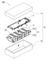
- FIG. 1 is a perspective view showing a power supply device according to a first embodiment.
- FIG. 2 is an exploded perspective view of the power supply device of FIG. 1 .
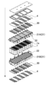
- FIG. 3 is an exploded perspective view of the battery block of FIG. 2 .
- FIG. 3 is an enlarged perspective view of the battery block of FIG. 2 .
- 5 is an enlarged plan view showing a lead plate of the power supply device of FIG. 4.
- FIG. 6 is an enlarged perspective view of a main portion of the fuse link portion of FIG. 5 .
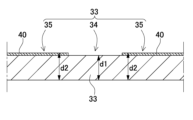
- 7 is a cross-sectional view taken along line VII-VII in FIG. 6.
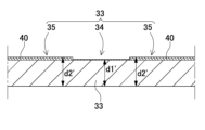
- FIG. 11 is an enlarged cross-sectional view showing a fuse link portion of a lead plate according to a second embodiment.
- FIG. 11 is an enlarged cross-sectional view showing a fuse link portion of a lead plate according to a third embodiment.
- FIG. 4 is a plan view showing a lead plate according to Comparative Example 1.
- FIG. 11 is a plan view showing a lead plate according to Comparative Example 2.
- the melting region is not coated with the coating material.
- the lead plate is entirely coated with the coating material except for the melting area.
- the length of the melting region is 10% to 70% of the length of the fuse link portion.
- the coating material is a material that increases the heat capacity of the lead plate.
- the coating material is made of an insulating material.
- the side of the lead plate that is coated with the coating material is insulated to prevent unintended conduction, thereby improving safety.
- the coating material is black paint.
- the power supply device of the present invention can be used as a driving power source for mobile objects such as electric carts, electric scooters, and assisted bicycles, as a power source for portable electrical devices such as walkie-talkies, electric cleaners, and power tools, as a backup power source for servers in stationary power storage applications, as a power supply device for home, business, and factory use, and even as a driving power source for vehicles such as hybrid cars and electric automobiles.
- a power supply device used as a driving power source for electric carts as one embodiment of the present invention.
- FIG. 1 A power supply device 100 according to a first embodiment of the present invention is shown in Figures 1 to 7.
- Figure 1 is a perspective view showing the power supply device 100 according to the first embodiment
- Figure 2 is an exploded perspective view of the power supply device 100 in Figure 1
- Figure 3 is an exploded perspective view of the battery block 2 in Figure 2
- Figure 4 is an enlarged perspective view of the battery block 2 in Figure 2
- Figure 5 is an enlarged plan view showing the lead plate 30 of the power supply device 100 in Figure 4
- Figure 6 is an enlarged perspective view of a main portion of the fuse link portion 33 in Figure 5
- Figure 7 is a cross-sectional view taken along line VII-VII in Figure 6.
- the power supply device 100 shown in these figures includes an exterior case 10, a battery block 2, and a circuit board 3.
- the exterior case 10 houses the battery block 2 and the circuit board 3. Any shape that has a storage space inside can be used as the exterior shape of the exterior case 10. In the example shown in Figures 1 and 2, the exterior case 10 is formed into a box shape that extends in one direction.
- the exterior case 10 is divided into an upper case 11 and a lower case 12.
- This exterior case 10 is preferably made of a material with excellent insulating properties, such as a resin such as polycarbonate or PC-ABS alloy.
- the exterior case may also be made of a metal material such as aluminum or its alloy.
- An internal space is provided inside the exterior case 10 to house the battery block 2 and the circuit board 3.
- the battery block 2 is also called a core pack.
- the battery block may be composed of multiple sub-blocks.
- the battery block 2 is composed of multiple secondary battery cells 1.
- the multiple secondary battery cells 1 are connected in series or in parallel via lead plates 30. In the example of FIG. 3 etc., 90 secondary battery cells are connected in 9 series and 10 parallel configurations.
- the number of series connections or parallel connections of the secondary battery cells constituting the battery block 2 can be set as desired according to the required specifications.
- the battery block 2 includes a battery holder 21 that stores multiple secondary battery cells 1.
- the battery holder 21 has multiple storage cylinders 22 that store the secondary battery cells 1 individually.
- each battery holder 21 is divided into two parts, upper and lower, to form sub-holders 21A and 21B, and the two divided storage cylinders 22 store the secondary battery cells 1 by sandwiching them from above and below.
- Such battery holders 21 can be made of a resin such as polycarbonate that has excellent insulating properties. Note that in the example of Figure 3 etc., the battery block 2 is composed of 90 secondary battery cells 1, but the number of secondary battery cells that make up the battery block is not limited to this and can be any number.
- Each secondary battery cell 1 may be a secondary battery cell having a cylindrical or rectangular external shape.
- cylindrical secondary battery cells 1 are used arranged vertically in a staggered pattern. Note that the number and arrangement of the secondary battery cells 1 are not limited to this example, and any number and arrangement may be appropriately adopted.
- cylindrical secondary battery cells may be arranged in a matrix.
- Each secondary battery cell 1 has a positive and negative electrode.
- the positive and negative electrodes are preferably provided on one end surface 1c of the secondary battery cell 1.
- the secondary battery cell 1 can be any known secondary battery, such as a lithium ion secondary battery, a nickel metal hydride battery, or a nickel cadmium battery. (Lead plate 30).
- Lead plates 30 are arranged on the side of the battery holder 21. As shown in FIG. 4, the lead plates 30 connect the electrodes of the end faces 1c of the secondary battery cells 1 to each other, connecting the multiple secondary battery cells 1 in series or parallel. The lead plates 30 connect the multiple battery cells 1 in parallel.
- the lead plates 30 are electrically connected by fixing pieces 32 protruding from multiple points of the base portion 31 that constitutes the main surface of the lead plates 30 to the end faces 1c of the secondary battery cells 1 using known methods such as spot welding, laser welding, resistance welding, and ultrasonic welding. These lead plates 30 are made of metal plates with excellent conductivity, such as nickel plates.
- the lead plates 30 also have fuse link portions 33 that cut off the current by melting in response to an overcurrent as a path to each fixing piece 32 (details will be described later).
- Insulating plate 4 is disposed on the end faces of the lead plates 30. In the example shown in Fig. 3 etc., the insulating plates 4 are formed to a size sufficient to cover the entire surfaces of the lead plates 30 of the battery block 2. Also, electrode windows 41 are partially opened to expose the electrode portions of the lead plates 30. These insulating plates 4 are made of materials with excellent insulating properties, such as paper or mica.
- Circuit board 3 The battery block 2 is connected to a circuit board 3 via lead plates 30.
- the circuit board 3 is equipped with a charge/discharge circuit that charges and discharges the secondary battery cells 1, and a protection circuit that monitors the voltage and temperature of the secondary battery cells 1 and cuts off the current in the event of an abnormality.
- the circuit board 3 is made of a glass epoxy board or the like. A board holder for holding such a circuit board 3 may also be provided.
- the lead plate 30 includes a base portion 31 constituting a main surface, fixing pieces 32 provided at a plurality of locations on the base portion 31 corresponding to the terminals of the secondary battery cell 1 for fixing the terminals of the secondary battery cell 1, and fuse link portions 33 connecting the base portion 31 and each fixing piece 32.
- the fuse link portions 33 are members for cutting off the current by melting when an overcurrent flows through the lead plate 30.
- FIG. 5 shows an enlarged view of the lead plate 30 in FIG. 4. As shown in this figure, the fuse link portion 33 extends in an arm shape from the base portion 31 to the fixing piece 32. In the example of FIG.
- the fuse link portion 33 is formed in an arc shape so as to fit around the periphery of the end surface 1c of the cylindrical secondary battery cell 1.
- the shape of the fuse link portion is not limited to this shape, and it may be any shape that can melt in response to an overcurrent.
- the fuse link portion 33 is provided with a fusion region 34 in a portion thereof that is more likely to melt in response to an overcurrent than other regions of the fuse link portion 33.
- a fusion region 34 in a portion thereof that is more likely to melt in response to an overcurrent than other regions of the fuse link portion 33.
- a coating material 40 is applied to the fuse link portion 33, and the melting region is defined by the film thickness.
- the fuse link portion 33 is coated with a coating material 40, and a non-fuse region 35, which is a covered region coated with the coating material 40, and a fuse region 34, which is a non-covered region not coated with the coating material 40, are formed in the fuse link portion 33.
- the thickness d1 of the fuse region 34 which melts in response to an overcurrent, in the fuse link portion 33 is made thinner than the thickness d2 of the region other than the fuse region 34, i.e., the non-fuse region 35.
- the non-fuse region 35 other than the fuse region 34 of the fuse link portion 33 is coated with the coating material 40 to increase the film thickness of the entire lead plate 30.
- the heat capacity of the coated region of the fuse link portion 33 is increased, and when an overcurrent is passed through the lead plate 30, the thin coating portion melts first, thereby making it possible to specify the fuse portion.
- the region to be fused can be defined while maintaining the original shape of the lead plate 30, there is an advantage that it can be easily applied at low cost.
- the coating material 40 is made of a material that increases the heat capacity of the lead plate 30. By applying such coating material 40 to the lead plate 30, the heat capacity of the coated area of the lead plate 30 is increased, making it more difficult to melt, and a difference in melting speed is created between the coated area and the melting area 34, making it possible for the melting area 34 to melt first.
- Black paint can be used as this type of coating material 40. Black paint is inexpensive, and the painting technology is well established, making it extremely easy to introduce. Coating the lead plate 30 with black paint changes the emissivity, making it less likely to melt.
- the melting region 34 is not coated with the coating material 40.
- the coating material 40 can be easily applied to only the non-melting region 35, excluding the melting region 34, in a manner similar to masking paint.
- a structure can be created in which the masked melting region 34 melts relatively earlier.
- the coating material 40 may be applied only to the fuse link portion 33 of the lead plate 30, or may cover the entire surface of the lead plate 30 except for the fusion region 34. This allows only the fusion region 34 to be masked and the coating material 40, such as black paint, applied to the surface, making it easy to create a difference in film thickness between the fusion region 34 and the other regions.
- an insulating material can be used as the coating material 40.
- the coating material 40 is applied to the entire lead plate 30, for example, as shown in FIG. 6, the back side of the fixing piece 32 of the lead plate 30 is fixed to the terminal of the secondary battery cell 1 to establish electrical continuity, while the insulating coating material 40 is applied to the front side of the lead plate 30, thereby improving the insulation of the front side of the lead plate 30 and preventing unintended electrical continuity, thereby improving safety.
- the fusing region 34 is preferably located in the middle of the fuse link portion 33. This allows the fuse link portion 33 to fuse stably in the fusing region 34, cutting off the current flowing through the lead plate 30.
- the fusing region 34 can be set appropriately depending on the manner in which the fuse link portion 33 is arranged in the battery module and the layout of other components such as nearby electronic components.
- the length of the melting region 34 is preferably 10% to 70% of the fuse link portion 33.
- the region on the fuse link portion 33 that is to be melted can be designed as desired depending on the surrounding materials, installation environment, etc.
- the coating material 40 is not applied to the fusing region 34, and the fusing of the region without the coating material 40 is accelerated to function as the fusing region 34.
- the present disclosure is not limited to this configuration, and the coating material 40 may be applied to the fusing region 34 as well, but the thickness of the coating material 40 may be thinned in the fusing region 34 to provide a difference in heat capacity between the fusing region 34 and other regions, making it easier to fuse.
- Such an example is shown in the cross-sectional view of FIG. 8 as a power supply device according to embodiment 2.
- the same members as those in embodiment 1 and the like described above are given the same reference numerals, and detailed description thereof will be omitted as appropriate.
- the fuse link portion 33 of the lead plate 30 shown in FIG. 8 is coated with the coating material 40 over the entire area including the fusion region 34, while the thickness d1' of the fusion region 34 is made thinner than the thickness d2' of the non-fusion region 35 other than the fusion region 34.
- the amount of coating material 40 in the fusion region 34 is smaller, so the heat capacity is lower than in the non-fusion region 35, and the effect of promoting fusion is obtained more than in the non-fusion region 35.
- the coating material 40 is also applied to the fusion region 34, so that the function of the coating material 40 can be added. For example, if an insulating material is applied as the coating material 40, insulation is added to the fusion region 34 as well, contributing to improved safety.
- the same coating material 40 is used, and the heat capacity is varied by changing the film thickness to adjust the local melting speed of the fuse link portion 33.
- the present disclosure is not limited to this configuration, and the melting speed can also be adjusted by changing the material of the coating material 40.
- Such an example is shown in the cross-sectional view of Figure 9 as a power supply device according to embodiment 3.
- the same members as those in embodiment 1 and the like described above are denoted by the same reference numerals, and detailed description thereof will be omitted as appropriate.
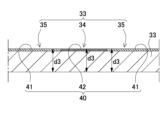
- the fuse link portion 33 of the lead plate 30 shown in FIG. 9 is coated with a coating material 40 over the entire area including the melting region 34, and the melting speed is controlled by applying two coating materials with different specific heats rather than the thickness of the coating material.
- a first coating material 41 having a first specific heat and a second coating material 42 having a second specific heat are used.
- the first specific heat of the first coating material 41 is set higher than the second specific heat of the second coating material 42.
- the non-melting region 35 other than the melting region 34 is coated with the first coating material 41.
- the melting region 34 is coated with the second coating material 42.
- the thicknesses of non-melt region 35 and melt region 34 are both set to the same thickness d3, but it is sufficient that the heat capacity of melt region 34 is sufficiently lower than the heat capacity of non-melt region 35, and the thicknesses may be different. "Sufficient” here refers to a difference that ensures that melting of melt region 34 occurs faster than melting of non-melt region 35.
- a method for manufacturing a power supply device in which a plurality of secondary battery cells 1 are electrically connected by a lead plate 30 is described below.
- a lead plate 30 having a fuse link portion 33 that cuts off current by melting in response to an overcurrent is prepared.
- at least a part of the fuse link portion 33 of this lead plate 30 is coated with a coating material 40, and a covered area coated with the coating material 40 and an uncoated area not coated with the coating material 40 are formed in the fuse link portion 33.
- the thickness of the fusion area 34 which is more likely to melt in response to an overcurrent than other areas in the fuse link portion 33, is made thinner than the other areas of the fuse link portion 33.
- this lead plate 30 is connected to a plurality of secondary battery cells 1.
- the heat capacity is increased by coating the fuse link portion 33, and when an overcurrent is applied to the lead plate 30, the thin coating part melts first, making it possible to specify the melting part.
- a lead plate 30 is prepared that has a fuse link portion 33 that cuts off current by melting in response to an overcurrent.
- a coating material 40 is coated with a coating material 40, and a covered area coated with the coating material 40 and an uncoated area not coated with the coating material 40 are formed in the fuse link portion 33.
- the thickness of the fusion area 34 which is more likely to melt in response to an overcurrent than other areas in the fuse link portion 33, is made thinner than the other areas of the fuse link portion 33.
- the heat capacity is increased by coating the fuse link portion 33, and when an overcurrent is passed through the lead plate 30, the thinner coating part melts first, thereby making it possible to specify the fusion part.
- the power supply device is attached to the electrical device to be driven and supplies power to the electrical device.
- the power supply device can be replaced to continue using the electrical device.
- the present invention is not limited to power supply devices of a replaceable type that mainly houses secondary battery cells, but can also be applied to configurations in which secondary battery cells are housed within the housing of electrical device.
- a power supply device is sufficient as long as it houses secondary battery cells in a case, and also includes power supply devices that have secondary battery cells built in for driving the electrical device itself within the housing.
- the present invention is not limited to replaceable power supply devices, but can also be applied to electrical devices that have built-in secondary battery cells.
- the power supply device and lead plate with fuse link function according to the present invention, as well as the manufacturing method thereof, can be suitably used as a power source for driving mobile objects such as electric carts and electric scooters. They can also be suitably used as a power source for wireless devices and portable electrical devices such as electric cleaners and power tools.
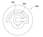
- DESCRIPTION OF SYMBOLS 100...power supply device 1...secondary battery cell 1c...end surface 2...battery block 3...circuit board 4...insulating plate 10...outer case 11...upper case 12...lower case 21...battery holder 22...storage tube 30...lead plate 31...base portion 32...fixing piece 33...fuse link portion 34...melt region 35...non-melt region 40...coating material 41...first coating material 42...second coating material 830...lead plate 833...fuse link 930...lead plate 933...fuse link 934...region that is prone to melting d1, d1'...thickness of melting region d2, d2'...thickness of non-melt region d3...non-melt region, thickness of melting region
Landscapes
- Chemical & Material Sciences (AREA)
- Chemical Kinetics & Catalysis (AREA)
- Electrochemistry (AREA)
- General Chemical & Material Sciences (AREA)
- Connection Of Batteries Or Terminals (AREA)
- Fuses (AREA)
Abstract
Le présent dispositif d'alimentation électrique comprend une pluralité de cellules de batterie secondaires, et une plaque de connexion qui connecte électriquement la pluralité de cellules de batterie secondaire. La plaque de connexion comprend une partie de liaison de fusible qui bloque l'électrification en étant fondue en réponse à une surintensité. Une section de la partie de liaison de fusible est pourvue d'une région de fusion qui est plus facilement fusionnée en réponse à une surintensité que d'autres régions. Dans la plaque de connexion, au moins une section de la partie de liaison de fusible est revêtue d'un matériau de revêtement. L'épaisseur de la région de fusion est rendue inférieure à celle des autres régions de la partie de liaison de fusible.
Applications Claiming Priority (2)
| Application Number | Priority Date | Filing Date | Title |
|---|---|---|---|
| JP2023-185155 | 2023-10-30 | ||
| JP2023185155 | 2023-10-30 |
Publications (1)
| Publication Number | Publication Date |
|---|---|
| WO2025094672A1 true WO2025094672A1 (fr) | 2025-05-08 |
Family
ID=95581998
Family Applications (1)
| Application Number | Title | Priority Date | Filing Date |
|---|---|---|---|
| PCT/JP2024/036828 Pending WO2025094672A1 (fr) | 2023-10-30 | 2024-10-16 | Dispositif d'alimentation électrique, plaque de connexion pourvue d'une fonction de liaison de fusible et procédé de fabrication associé |
Country Status (2)
| Country | Link |
|---|---|
| TW (1) | TW202534936A (fr) |
| WO (1) | WO2025094672A1 (fr) |
Citations (4)
| Publication number | Priority date | Publication date | Assignee | Title |
|---|---|---|---|---|
| WO2011007535A1 (fr) * | 2009-07-17 | 2011-01-20 | パナソニック株式会社 | Élément de connexion de piles et module de piles l'utilisant |
| JP2017084606A (ja) * | 2015-10-28 | 2017-05-18 | トヨタ自動車株式会社 | 電池接続構造 |
| WO2020218223A1 (fr) * | 2019-04-25 | 2020-10-29 | 三洋電機株式会社 | Ligne de détection de tension et module de ligne de détection de tension |
| JP2022013616A (ja) * | 2020-07-02 | 2022-01-18 | 本田技研工業株式会社 | 電池 |
-
2024
- 2024-10-15 TW TW113139106A patent/TW202534936A/zh unknown
- 2024-10-16 WO PCT/JP2024/036828 patent/WO2025094672A1/fr active Pending
Patent Citations (4)
| Publication number | Priority date | Publication date | Assignee | Title |
|---|---|---|---|---|
| WO2011007535A1 (fr) * | 2009-07-17 | 2011-01-20 | パナソニック株式会社 | Élément de connexion de piles et module de piles l'utilisant |
| JP2017084606A (ja) * | 2015-10-28 | 2017-05-18 | トヨタ自動車株式会社 | 電池接続構造 |
| WO2020218223A1 (fr) * | 2019-04-25 | 2020-10-29 | 三洋電機株式会社 | Ligne de détection de tension et module de ligne de détection de tension |
| JP2022013616A (ja) * | 2020-07-02 | 2022-01-18 | 本田技研工業株式会社 | 電池 |
Also Published As
| Publication number | Publication date |
|---|---|
| TW202534936A (zh) | 2025-09-01 |
Similar Documents
| Publication | Publication Date | Title |
|---|---|---|
| US11575182B2 (en) | Bonding connector with fuse section and battery module with insulative P-group separator | |
| CN101997136B (zh) | 二次电池及其制造方法 | |
| CN101802953B (zh) | 保护元件及充电电池装置 | |
| US10601018B2 (en) | Electrode lead for a secondary battery, a pouch type secondary battery and a battery module comprising the same | |
| CN103066339B (zh) | 整体式单元电压感测线路熔断装置 | |
| US9685681B2 (en) | Battery pack | |
| KR20230062466A (ko) | 집전체, 전극 시트, 전극 조립체, 전지 셀, 전지 및 전력 소비 장치 | |
| JP5952673B2 (ja) | 保護素子及びバッテリパック | |
| EP2273588B1 (fr) | Bloc-batterie et son procédé de fabrication | |
| CN112787047A (zh) | 转接片、二次电池及电池模组 | |
| CN103534839A (zh) | 用于二次电池的部件及其制造方法、以及使用该部件制造的二次电池和多电池系统 | |
| US20100251540A1 (en) | Rechargeable battery and its fabrication method | |
| KR102332338B1 (ko) | 배터리 팩 | |
| JP2011192550A (ja) | 二次電池 | |
| CN110247058A (zh) | 可再充电电池 | |
| KR20140125657A (ko) | 이차전지 | |
| CN102610846A (zh) | 电池芯、电池芯构成的电池组件及制造电池组件的方法 | |
| CN214280158U (zh) | 转接片、二次电池及电池模组 | |
| US20240154278A1 (en) | Battery cell, method and apparatus for manufacture same, battery, and power consuming device | |
| JP7704460B2 (ja) | 開口部を含むパターンヒューズ及びこれを含む電池モジュール | |
| US20230299432A1 (en) | Electrode-Lead-Integrated Electrode Assembly and Method of Manufacturing the Same | |
| JP2024504661A (ja) | パターンヒューズ及びその製造方法 | |
| WO2025094672A1 (fr) | Dispositif d'alimentation électrique, plaque de connexion pourvue d'une fonction de liaison de fusible et procédé de fabrication associé | |
| WO2014199911A1 (fr) | Élément de protection et boîtier dans lequel un élément de protection est monté | |
| KR20230061246A (ko) | 패턴 퓨즈 및 이의 제조방법 |
Legal Events
| Date | Code | Title | Description |
|---|---|---|---|
| 121 | Ep: the epo has been informed by wipo that ep was designated in this application |
Ref document number: 24885446 Country of ref document: EP Kind code of ref document: A1 |