WO2025100007A1 - 刃体交換式剃刀および替刃収容容器 - Google Patents
刃体交換式剃刀および替刃収容容器 Download PDFInfo
- Publication number
- WO2025100007A1 WO2025100007A1 PCT/JP2024/027424 JP2024027424W WO2025100007A1 WO 2025100007 A1 WO2025100007 A1 WO 2025100007A1 JP 2024027424 W JP2024027424 W JP 2024027424W WO 2025100007 A1 WO2025100007 A1 WO 2025100007A1
- Authority
- WO
- WIPO (PCT)
- Prior art keywords
- blade
- support
- razor
- cover
- magnet
- Prior art date
- Legal status (The legal status is an assumption and is not a legal conclusion. Google has not performed a legal analysis and makes no representation as to the accuracy of the status listed.)
- Pending
Links
Images









Classifications
-
- B—PERFORMING OPERATIONS; TRANSPORTING
- B26—HAND CUTTING TOOLS; CUTTING; SEVERING
- B26B—HAND-HELD CUTTING TOOLS NOT OTHERWISE PROVIDED FOR
- B26B21/00—Razors of the open or knife type; Safety razors or other shaving implements of the planing type; Hair-trimming devices involving a razor-blade; Equipment therefor
- B26B21/08—Razors of the open or knife type; Safety razors or other shaving implements of the planing type; Hair-trimming devices involving a razor-blade; Equipment therefor involving changeable blades
- B26B21/14—Safety razors with one or more blades arranged transversely to the handle
-
- B—PERFORMING OPERATIONS; TRANSPORTING
- B26—HAND CUTTING TOOLS; CUTTING; SEVERING
- B26B—HAND-HELD CUTTING TOOLS NOT OTHERWISE PROVIDED FOR
- B26B21/00—Razors of the open or knife type; Safety razors or other shaving implements of the planing type; Hair-trimming devices involving a razor-blade; Equipment therefor
- B26B21/40—Details or accessories
Definitions
- This disclosure relates to a blade-replaceable razor (hereinafter simply referred to as a razor) in which only the blade portion can be replaced, and a replacement blade storage container.
- a blade-replaceable razor hereinafter simply referred to as a razor
- Patent Document 1 discloses a replaceable blade razor in which only the blade body, which is an integrated unit of multiple blades, can be replaced.
- This replaceable blade razor is equipped with a holder having a handle and a head, and a razor head having a blade base member and a cover member that houses the blade body.
- the blade base member and cover member are supported by a support shaft so that they can swing at the bottom end of the head of the holder.
- a locking claw portion is arranged at the top end of the cover member, and the locking claw portion can be hooked and unhooked from a locking shaft portion arranged at the top end of the blade base member, allowing the cover member and the blade base member to be opened and closed.
- left and right locking claw portions are arranged at the top end of the blade base member, and the left and right locking claw portions can be hooked and unhooked from locking recesses provided at the top end of the head of the holder, allowing the blade base member and the head of the holder to be opened and closed.
- a permanent magnet is provided inside the head of the holder to magnetically attract the blade body.
- the cover member and the blade base member are attached to the bottom end of the head of the holder so that they can swing separately, and a mechanism is required to separately open and close the cover member and the blade base member, and open and close the blade base member and the head of the holder. This makes the structure of the razor head complicated.
- the objective of this disclosure is to provide a razor and blade storage container that has a simple structure but allows for replacement of only the blade portion.
- the first invention is a razor having a handle portion (2) extending in one direction and a razor head (1) attached to a tip portion (50) of the handle portion on one side in the one direction, the razor head having a blade portion (10) equipped with a blade body (11) whose longitudinal direction is a direction intersecting the one direction, a support portion (20) connected to the tip portion of the handle portion and having a mounting surface (220) on which the blade portion is mounted with the cutting edge (11a) of the blade body facing the side connected to the handle portion, a support portion (20) that magnetically attracts the blade portion to the mounting surface, and a cover portion (30) that is magnetically attached to the support portion and that sandwiches the blade portion together with the support portion while exposing the blade portion, and in which only the blade portion can be replaced when the cover portion is detached from the support portion.
- the blade portion is magnetically attached to the support, the blade portion can be magnetically attached to the support even when the cover portion is removed, and can be easily removed from the support against the magnetic force. Also, by simply bringing the support close to a new blade portion, the blade portion is magnetically attached to the support, making it easy to replace the blade portion. This makes it possible to replace only the blade portion.
- the user is less likely to injure themselves by touching the cutting edge or the psychological anxiety that may arise from touching the blade, making it easier for the user to replace the blade.
- the support is equipped with a magnet (23) to which the blade and cover are magnetically attracted, and the magnetic attraction between the magnet and the cover is stronger than the magnetic attraction between the magnet and the blade. Therefore, the cover is integrated with the support by a relatively strong magnetic attraction, and does not come off the support during shaving. In addition, the blade is attracted to the support by a relatively weak magnetic attraction, so the blade can be easily removed from the support when replacing it.
- the blade is sandwiched between the cover and the support, so the blade will not come off unless the cover is removed, and because the cover is attached with a relatively strong magnetic attraction force, the blade is less likely to come off, allowing the razor to be used safely.
- the blade is attached to the support with a relatively weak magnetic attraction force, making it easier to remove, and the user can easily remove the blade.
- the distance between the magnet and the part of the blade that is magnetically attracted or attracted to the magnet is longer than the distance between the magnet and the part of the cover that is magnetically attracted to the magnet. In this way, the magnetic attraction force can be adjusted by simply changing the distance between the magnet and the cover and the distance between the magnet and the blade, allowing the razor head to have a simple configuration.
- the cover portion has a window portion (35) that exposes the blade body, a cover surface (30a) that faces the mounting surface and clamps the blade body portion together with the support, and an outer peripheral wall (31) that is disposed on the outer edge of the cover surface, surrounds the outer edge of the blade body portion, and abuts against the outer edge of the mounting surface of the support.
- the blade part can be positioned and held by sandwiching it between the cover surface and the support and surrounding the outer edge of the blade part with the outer wall. Also, by configuring the outer wall of the cover part to abut against the outer edge of the mounting surface, the cover part can be positioned and held relative to the support. This can reduce rattling of the blade part and cover part, allowing for more stable shaving.
- the blade section is configured to include a plurality of blades arranged in a direction perpendicular to the longitudinal direction, a frame (13) that is disposed between the blades and the support body, supports the blades, and is magnetically attached or attracted to the magnet, and a blade stand member (12) that is disposed between the blades and the frame and is integrated with the blades and the frame.
- the blade section can be magnetically attached to the support body by magnetically attaching or attracting the frame to the magnet.
- the frame is provided with a first gripping portion (133) that protrudes beyond the support at a portion of the razor head that is located opposite the portion where the support is connected to the handle. Since the frame is provided with the first gripping portion, the user can easily remove the blade from the support by simply gripping the first gripping portion. Also, since the first gripping portion is positioned opposite the portion of the razor head where the support is connected to the handle, the first gripping portion can be positioned in the opposite direction to the direction in which the cutting edge of the blade is pointed. Therefore, even if the user touches the blade when removing the blade from the support, the user touches it in the opposite direction to the cutting direction, so the user can be protected from injury. This can also reduce the psychological anxiety that the user may feel that they may be injured or that they may be injured by touching the blade, making it easier for the user to replace the blade.
- the outer peripheral wall of the cover is provided with a second gripping portion (31a) that protrudes beyond the support and covers the first gripping portion at a portion of the razor head opposite the portion where the support is connected to the handle.
- the second gripping portion By providing the second gripping portion so as to cover the first gripping portion in this manner, the second gripping portion can be gripped separately from the first gripping portion, and the cover and the blade can be removed separately.
- the second gripping portion is disposed on the opposite side of the razor head from the portion where the support is connected to the handle, the second gripping portion can be disposed in the opposite direction to the direction in which the cutting edge of the blade is pointed. Therefore, even if the user touches the blade when removing the cover from the support, the touch will be in the opposite direction to the cutting direction, and the user can be protected from injury.
- the cover and blade parts that are magnetically attracted to the magnet are made of magnetic metal, and the razor head and handle are all made of metal.
- a full metal body can be used to provide a razor with a solid feel.
- a full metal body can be used to create a unified structure, and the design is simple, does not tire of, and has a luxurious feel.
- the blade part is replaced when it becomes dull, but it is desirable to use the other parts (handle, cover, support) for a long time without replacing, thereby reducing waste. For this reason, by using metal to improve the durability of each part and making the product luxurious and not tire of, users can use it for a long time, which leads to reduced waste.
- the ninth invention is a blade storage container that stores a blade portion used in a blade-replaceable razor according to any one of the fifth to seventh inventions, and includes a container body (610) having a recess (611) in which the blade portion is stored and a flat flange portion (612) protruding around the recess, and a lid (620) that is attached to the flange portion while covering the blade portion stored in the recess and that can be removed from the flange portion to allow the blade portion to be removed, with the blade side facing the bottom surface of the recess and the frame side facing the opposite side to the bottom surface of the recess, and the blade portion being stored in the recess.
- the blade can be removed simply by removing the lid. Furthermore, while the blade is still placed in the recess of the container body, it can be attached to the support by simply magnetically attracting the blade to the magnet on the support. This allows the user to easily and safely replace the blade without having to touch it.
- the user is less likely to injure themselves by touching the blade edge, or the user's psychological anxiety that they may injure themselves by touching the blade, making it easier for the user to replace the blade.
- the blade storage container can be separated one by one and used like a one-day contact lens.
- the blade storage container can be made thin and can be stored in a storage box or the like in multiple layers, making it possible to reduce storage space even when storing a large number of blades.
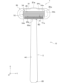
- FIG. 1 is a perspective view of a razor according to a first embodiment, as viewed from diagonally above and to the front right.
- FIG. 2 is a front view of the razor shown in FIG.
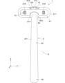
- FIG. 3 is a bottom view of the razor shown in FIG.
- FIG. 4 is a right side view of the razor shown in FIG.
- FIG. 5 is a rear view of the razor shown in FIG.
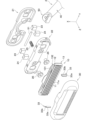
- FIG. 6 is an exploded perspective view of the razor shown in FIG. 1, as viewed from diagonally above and to the front right.
- 7 is an exploded perspective view of the razor shown in FIG. 1, as viewed obliquely from below and rear on the left.
- FIG. 8A is an enlarged view of the blade portion in FIG. 8B is an enlarged view of the blade portion in FIG.
- FIG. 8A is an enlarged view of the blade portion in FIG. 8B is an
- FIG. 9A is a perspective view of a blade in an exploded view of the blade portion.
- FIG. 9B is an exploded perspective view of the blade base member of the blade body portion.
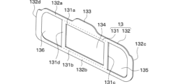
- FIG. 9C is a perspective view of the frame in an exploded view of the blade body.
- FIG. 10 is a perspective view showing the razor with the cover and the blade removed.
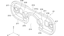
- FIG. 11A is an enlarged view of the back plate in FIG.
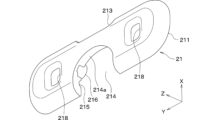
- FIG. 11B is an enlarged view of the back plate in FIG.
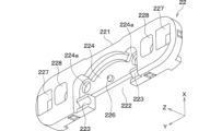
- FIG. 12A is an enlarged view of the housing in FIG.
- FIG. 12B is an enlarged view of the housing in FIG.
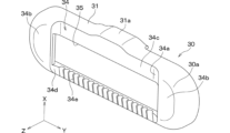
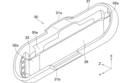
- FIG. 13A is an enlarged view of the cover portion in FIG.
- FIG. 13B is an enlarged view of the cover portion in FIG.
- [Configuration of Razor S] 1 to 5 is configured to have a razor head 1 and a handle portion 2, and is used for shaving unwanted hair.
- the razor S of this embodiment has a full metal body in which at least all of the parts exposed to the outside are made of metal, and in this embodiment, the surface exposed to the outside is a mirror-finished body.
- the drawings attached to this specification show the X-axis, Y-axis and Z-axis.
- the vertical direction of the razor head 1 when viewed from the front is called the X-axis
- the width direction of the razor head 1 perpendicular to the X-axis is called the Y-axis
- the thickness direction of the razor head 1 perpendicular to the X-axis and Y-axis is called the Z-axis.
- the razor head 1 side of the razor S is called the tip of the razor S
- the opposite side is called the rear end of the razor S.
- the right and left sides of the razor S are called the right and left sides of the razor S, respectively, and the upper and lower sides along the X-axis direction are called the upper and lower sides of the razor S, respectively.
- the front side of the paper along the Z-axis in Fig. 2 i.e. the side shown in Fig. 2
- the front side of the razor S is called the front side of the razor S
- the opposite side, the other side of the paper is called the back side of the razor S.
- the sides that correspond to the right side, left side, upper side, lower side, front side, and back side of the razor S are referred to as the right side, left side, upper side, lower side, front side, and back side of each component.
- the razor head 1 is a part that constitutes the blade portion of the razor S that performs shaving.
- the razor head 1 is generally shaped like an ellipse with the X-axis direction as the minor axis and the Y-axis direction as the major axis, and has a structure having a predetermined thickness in the Z-axis direction.
- the head front surface, which is the front side of the razor head 1, and the head back surface, which is the opposite side, are both shaped like a rectangle with rounded outer edges in the Z-axis direction, which is the thickness direction of the razor head 1. Therefore, the razor head 1 is shaped like a rounded blade portion.
- the razor head 1 includes a blade portion 10, a support 20, and a cover portion 30.
- the blade unit 10 is a replaceable part of the razor S, and as shown in Figures 6 to 9, is composed of a blade 11, a blade base member 12, and a frame 13.
- the blade 11, the blade base member 12, and the frame 13 are all made of metal.
- the blades 11 are rectangular with their long sides in the Y-axis direction, and multiple blades (here five) are arranged along the X-axis direction at a predetermined angle with respect to the X-axis perpendicular to the long sides.
- Each blade 11 has a cutting edge 11a, and as shown in FIG. 1, the cutting edge 11a of each blade 11 faces downward, which is the side that is connected to the handle portion 2, and the multiple blades 11 are arranged so that the cutting edges 11a are evenly spaced. Therefore, shaving can be performed by moving the razor head 1 downward.
- the direction in which the razor head 1 is moved when shaving i.e., the downward direction, will also be referred to as the shaving direction.
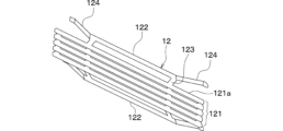
- the blade stand member 12 is a member in which multiple blades 11 are joined together by welding or the like to form an integrated unit.
- the blade stand member 12 has a spring structure, and the elastic force of this spring structure is used to soften the impact on the skin during shaving, and also prevents the blade body portion 10 from rattling when it is clamped between the support 20 and the cover portion 30.
- the blade stand member 12 has an installation base portion 121, legs 122, support portions 123, and leaf spring portions 124.
- the installation base 121 is a base on which multiple blade bodies 11 are placed, and has multiple joints 121a arranged in a stepped pattern, with the multiple joints 121a connected by supports 123.
- Each joint 121a extends along the Y axis and is linearly aligned with the blade body 11.
- the surface of each joint 121a that serves as the joint surface for the blade body 11 is flat, and the surfaces are arranged in the X axis direction so that they are parallel to each other.
- the surface of each joint 121a is inclined with respect to the XY plane, and each blade body 11 is spot-welded to each joint 121a, so that each blade body 11 is integrated with the installation base 121 in a state inclined with respect to the XY plane.
- the support portion 123 extends in the X-axis direction so as to intersect with each joint 121a and each leg portion 122, and connects each joint 121a and each leg portion 122.
- the support portion 123 is bent so that each joint 121a is arranged in a staircase shape, and is bent so that the legs 122 are located behind each joint 121a at the portions connected to each leg 122.
- the leaf spring portion 124 is configured by bending both ends of each leg portion 122 away from the blade body 11. When a force is applied to the leaf spring portion 124 in the Z-axis direction, it elastically deforms and generates an elastic reaction force. The tip of the leaf spring portion 124 protrudes from the rear side of the frame 13, and when the blade body portion 10 is attached to the support body 20, the tip of the leaf spring portion 124 comes into contact with the mounting surface 220 of the support body 20.
- the blade base member 12 is formed, for example, by pressing a metal plate.
- the joints 121a are connected by support parts 123, but the places between the joints 121a that are not connected to the support parts 123 can be punched out and bent backwards to form bent parts 121b, which are left connected to the joints 121a, thereby reinforcing the joints 121a.
- the support parts 123 are formed in a position corresponding to the first frame part 131 of the frame 13, the bent parts 121b can be prevented from interfering with the frame 13.
- the frame 13 holds the blade 11 and blade stand member 12, and is magnetically attached or attracted to the support 20 described below. As shown in Figures 8B and 9C, the frame 13 has a first frame portion 131 and a second frame portion 132.
- the first frame portion 131 and the second frame portion 132 are integrated into one component, with both the front and back sides being flat, and are formed, for example, by punching a metal plate or metal forming.
- the first frame portion 131 is shaped like a rectangular frame, and is the portion to which the blade base member 12 is joined. Specifically, the first frame portion 131 is composed of an upper beam portion 131a and a lower beam portion 131b that constitute one of two opposing sides along the Y-axis direction, and a right beam portion 131c and a left beam portion 131d that constitute the other of two opposing sides along the X-axis direction.
- the legs 122 are joined to the surfaces of the upper beam portion 131a and the lower beam portion 131b, and the blade base member 12 is fixed to the frame 13 with the support portion 123 positioned on the right beam portion 131c and the left beam portion 131d, and the blade body 11 is also fixed to the frame 13 via the blade base member 12.
- the second frame portion 132 has an oval frame shape, and is connected to the inside of the first frame portion 131.
- the second frame portion 132 is composed of an upper beam portion 132a and a lower beam portion 132b, and a right semicircular beam portion 132c and a left semicircular beam portion 132d, with the upper beam portion 132a and the lower beam portion 132b being connected to the upper beam portion 131a and the lower beam portion 131b of the first frame portion 131, respectively, and the right semicircular beam portion 132c and the left semicircular beam portion 132d being arranged to protrude outward from the right beam portion 131c and the left beam portion 131d of the first frame portion 131, respectively.
- the second frame portion 132 is shaped like an oval frame, but at the center of the upper beam portion 132a, it protrudes outward on the opposite side to the first frame portion 131, and this protruding portion forms the first grip portion 133.
- an opening 134 is formed on the inside of the first frame portion 131, an opening 135 is formed between the right beam portion 131c and the right semicircular beam portion 132c, and an opening 136 is formed between the left beam portion 131d and the left semicircular beam portion 132d.
- the support 20 is connected to one end of the handle 2 as shown in Fig. 10, and is a part that supports the blade 10 and the cover 30.
- the support 20 has a substantially elliptical shape when viewed from the front side, with the long axis along the Y-axis direction and the short axis along the X-axis direction.
- the support 20 is connected to the handle 2 at the center of the lower side of the elliptical shape.
- the support 20 has a back plate 21, a housing 22, a magnet 23, a magnet holder 24, a spring 25, and a screw 26 as shown in Figs. 6 and 7.
- the support 20 is one of the parts that constitute the body of the razor S, and the back plate 21, the housing 22, and other parts that constitute the support 20 and are exposed to the outside are made of metal, and the surfaces exposed to the outside are mirror-finished.
- the rear plate 21 is a part that constitutes the rear surface of the head, which is the rear side of the razor head 1. As shown in FIG. 11A, the rear plate 21 has a substantially elliptical outer shape when viewed from the front side.
- the rear plate 21 has an outer peripheral wall 211 that follows the outer edge of the elliptical shape, and inside this outer peripheral wall 211, a recess 212 that is recessed in an elliptical shape from the front side to the back side is formed. A part of the housing 22 and the like are placed in this recess 212.
- This groove 213 is formed in a position corresponding to the first gripping portion 133 of the frame 13 described above and the second gripping portion 31a of the cover portion 30 described below, and is sized so that the first gripping portion 133 and the second gripping portion 31a protrude from the groove 213 when the razor head 1 is viewed from the back side as shown in Figure 5.
- a part of the outer peripheral wall 211 is cut out to form a semicircular connecting recess 214.
- the tip of the handle part 2 is placed in this connecting recess 214 or the like to connect the support 20 and the handle part 2.
- the support 20 may be fixed to the handle part 2 to form a fixed head structure in which the razor head 1 cannot be swung relative to the handle part 2, in this embodiment, the razor head 1 is swung relative to the handle part 2.
- a pair of bearing parts 215 are arranged on both the left and right sides of the connecting recess 214.
- the shaft part 51 attached to the tip of the handle part 2 shown in Figures 6 and 7, which will be described later, is fitted into the bearing part 215, and the razor head 1 can be swung relative to the handle part 2 around an axis centered on the shaft part 51.
- the upper end wall 214a of the connecting recess 214 protrudes from the bottom surface of the recess 212 and is shaped to correspond to the tip shape of the handle part 2.
- a pair of cylindrical female threaded portions 216 are provided on the upper side of the bearing portion 215 on both the left and right sides of the connecting recess 214. Furthermore, seats 217 for the magnet 23 are formed on both the left and right sides of the pair of female threaded portions 216. The periphery of the seat 217 is partially recessed from the bottom surface of the recess 212, giving it a shape that protrudes from the surrounding area. Furthermore, between each of the female threaded portions 216 and each of the seats 217 on both the left and right sides, through holes 218 are formed that penetrate the front and back of the back panel 21.
- the rear side of the back plate 21 that forms the back surface of the head has an oval shape with the outer edge rounded in the Z-axis direction, which is the thickness direction of the razor head 1.
- the housing 22 is a component that is connected to the back plate 21 and, together with the back plate 21, forms the external shape of the support 20. It is a separate component from the back plate 21 in order to accommodate the magnet 23 and the tip 50 of the handle portion 2, which will be described later, inside the support 20.
- the blade portion 10 is placed on one surface of the front side of the housing 22, which serves as the placement surface 220.
- the housing 22 also has a substantially oval outer shape when viewed from the front. The major and minor axes of the oval shape correspond in size to the recess 212 of the back plate 21.
- a groove 221 is formed by cutting out a portion of the wall surface of the outer edge of the housing 22. This groove 221 is located in a position and has a shape corresponding to the groove 213 formed in the back plate 21, and is sized so that the first gripping portion 133 and the second gripping portion 31a protrude from the groove 213 when the razor head 1 is viewed from the back side as shown in FIG. 5.
- a portion of the outer wall surface of the housing 22 is cut out to form a rectangular connecting recess 222 in which the tip 50 of the handle portion 2 is placed.
- a pair of bearing portions 223 are arranged in positions corresponding to the bearing portions 215 of the back panel 21.
- a shaft portion 51 attached to the tip portion 50 of the handle portion 2 is fitted into these bearing portions 223 as well, thereby realizing the swivel head structure described above.
- a recess 224 is formed above the connecting recess 222 on the rear side of the housing 22, recessed from the rear side to the front side.
- the recess 224 is shaped to correspond to the upper end wall 214a and the female threaded portion 216 of the connecting recess 214 on the back plate 21, and a pair of through holes 224a is formed at a position corresponding to the female threaded portion 216.
- the through holes 224a reach the mounting surface 220, and as shown in FIG. 12A, a countersink 225 is formed around the through holes 224a on the mounting surface 220.
- a cylindrical protruding spring attachment portion 226 is formed above the connecting recess 222 on the bottom surface of the recess 224, and the spring 25 is fitted into the spring attachment portion 226.
- a pair of storage sections 227 are formed on both the left and right sides of the pair of through holes 224a in the housing 22, in which the magnets 23 and magnet holders 24 are stored.
- Each storage section 227 is recessed into a roughly rectangular parallelepiped shape.
- the thickness of the housing 22 is changed at the position where each storage section 227 is formed. Specifically, when viewed from the Z-axis direction, the thickness of the housing 22 is made thicker at portion 22a of each storage section 227 that is located inside the housing 22 and overlaps with the mounting surface 220 than at portion 22b that is located outside the mounting surface 220. In this embodiment, some of the housing 22 remains at portion 22a and no housing 22 remains at portion 22b, but some of the housing 22 may remain at portion 22b.
- the front surface of portion 22a forms part of the mounting surface 220, and is the location where the blade portion 10, specifically the frame 13, is magnetically attached or attracted.
- Portion 22b is the location where the cover portion 30 is magnetically attached.
- the thickness of the housing 22 is made thicker in portion 22a than in portion 22b.
- a through hole 228 is formed that penetrates the front and back of the housing 22.
- This through hole 228 is positioned and shaped to correspond to the through hole 218 formed in the rear panel 21, and is connected to the through hole 218 to communicate between the inside and outside of the razor head 1. Therefore, when the razor head 1 is washed with water, dirt and water from inside the razor head 1 can be discharged through the through holes 218, 228.
- holding pieces 229 are formed at the four corners of the mounting surface 220, at positions further outward in the X-axis direction than the storage section 227, protruding from the mounting surface 220.
- the holding pieces 229 have an inner wall surface 229a that contacts the mounting surface 220 and is curved in an arc shape, allowing the frame 13 to be positioned.
- the magnet 23 is made of a permanent magnet, and is rectangular in shape as shown in Figures 6 and 7, with a size that corresponds to the storage section 227.
- the material of the magnet 23 is arbitrary, but if an alloy magnet or the like is used, the magnet 23 can also be made of metal, and here the magnet 23 is also made of metal.
- the magnet holder 24 is provided as necessary and is arranged to surround the magnet 23, and is U-shaped when viewed from the X-axis direction as shown in Figures 6 and 7. By housing the magnet 23 in the housing section 227 while surrounded by the magnet holder 24, rattling of the magnet 23 relative to the housing 22 is suppressed.
- the spring 25 is a compression coil spring and is attached to the spring attachment portion 226.
- the spring 25 is disposed between the bottom surface of the recess 224 in the housing 22 and the tip 50 of the handle portion 2, and biases the tip 50 of the handle portion 2 with a compression reaction force.
- the handle portion 2 is biased clockwise around the shaft portion 51 relative to the razor head 1.
- the initial position is the position where a bottom portion 50c (described later) of the tip 50 of the handle portion 2, which is disposed in the connecting recess 222 of the housing 22, abuts against the bottom surface of the connecting recess 222, and when no load is applied to the razor head 1, the compression reaction force of the spring 25 causes the handle portion 2 to be positioned in the initial position.
- a load is applied to the razor head 1 during shaving, and a clockwise moment is applied to the razor head 1 about the shaft 51 when viewed from the right side of the razor S, the razor head 1 swings against the compression reaction force of the spring 25.
- the screw 26 serves to integrate the housing 22 and the rear panel 21.
- the screw 26 is fastened to the female threaded portion 216 through the through hole 224a, thereby fixing the housing 22 to the rear panel 21.
- a countersink 225 is formed around the through hole 224a in the mounting surface 220, so that the head of the screw 26 fits into the countersink 225, preventing the screw 26 from protruding.
- cover portion 30 is a component that covers the outer edge of the blade body portion 10 while exposing the cutting edge 11a of the blade body 11 at the center.
- the razor head 1 is formed by attaching the cover portion 30 to the support body 20 so that the cover portion 30 surrounds the outer edge of the blade body portion 10 and the outer edge of the housing 22.
- the cover portion 30 is one of the components that constitute the body of the razor S, is made of metal, and the surface exposed to the outside is a mirror finish.
- the cover portion 30 has a shape that is approximately an ellipse when viewed from the front side.
- the wall surface that constitutes the front side of the cover portion 30 is the cover surface 30a, and the surface of this cover surface 30a constitutes the head surface.
- the cover portion 30 has an outer peripheral wall 31 that follows the outer edge of the ellipse shape as shown in FIG. 13A, and a recess 32 that is recessed in an ellipse shape from the back side to the front side is formed inside the outer peripheral wall 31 as shown in FIG. 13B.
- the bottom surface of the recess 32 is constituted by the back surface of the cover surface 30a, and the inner wall surface of the recess 32 is constituted by the outer peripheral wall 31.
- the blade portion 10, part of the housing 22, etc. are arranged in this recess 32.
- the shape inside the recess 32 corresponds to the shape of the blade portion 10 and the housing 22. Therefore, the cover portion 30 can be attached to the support body 20 without any rattling.
- the cover portion 30 is attached to the support 20
- the blade portion 10 is sandwiched between the back surface of the cover surface 30a of the cover portion 30 and the support 20.
- a part of the bottom surface of the recess 32 abuts against both ends of the blade 11, and a load is applied that presses the blade portion 10 toward the housing 22. Therefore, when the cover portion 30 is attached to the support 20, the elastic force of the leaf spring portion 124 and the bending of each part of the blade portion 10 also suppress rattling of the blade portion 10.
- seats 32a are provided at both ends in the Y-axis direction within the recess 32.
- An attachment 33 shown in Figures 6 and 7 is fixed to the seats 32a.
- the attachment 33 is a part that is magnetically attracted to the magnet 23.
- the cover part 30 is attached to the support body 20, the attachment 33 is magnetically attracted to the magnet 23 at the part 22b of the housing 22. If the cover part 30 is made of a magnetic metal, the seat 32a can be directly magnetically attracted to the magnet 23 without the attachment 33. However, if the attachment 33 is attached, the seat 32a is magnetically attracted to the magnet 23 via the attachment 33, so the cover part 30 does not need to be made of a magnetic metal.
- the seat 32a is formed by partially protruding the bottom surface of the recess 32, and one attachment 33 is arranged to cover each seat 32a.
- Each attachment 33 is a V-shaped member when cut in the YZ plane, and has an inner wall surface 33a along the XZ plane and an adhesion surface 33b arranged at the tip of the seat 32a along the XY plane.
- the adhesion surface 33b is magnetically attracted to the magnet 23, and the cover 30 is integrated with the support 20.
- the distance between both attachments 33 is aligned with the dimensions of the mounting surface 220 and the frame 13, and the mounting surface 220 and the blade 10 are arranged between both attachments 33 when the cover 30 is attached to the support 20.
- the front side of the cover surface 30a is the skin contact surface 34.
- This skin contact surface 34 comes into contact with the user's skin when shaving with the razor S.
- a substantially rectangular window 35 is formed in the skin contact surface 34, penetrating from the front side to the back side of the cover part 30 and with the Y-axis direction as the longitudinal direction. The blade 11 is exposed from the cover part 30 through this window 35.
- a recess 34a is formed by recessing the skin contact surface 34.
- a semicircular flat surface 34b is formed on both sides of the skin contact surface 34 in the horizontal direction sandwiching the window 35 and the recess 34a.
- the cutting edge 11a of the blade 11 is protruded from the bottom surface of the recess 34a to the front side, enabling a close shave.
- both ends of the blade body 11 are covered by flat surfaces 34b, preventing both ends of the blade body 11 from catching on the user's skin during shaving.
- the bottom surface of the recess 34a of the skin contact surface 34 is flat on the upper side 34c located above the window 35, i.e., on the rear side in the shaving direction.
- the lower side 34d located below the window 35, i.e., on the front side in the shaving direction, has a structure in which multiple slots 34e extending in the X-axis direction are arranged in the Y-axis direction.
- the cover portion 30 has a generally oval shape when viewed from the front side, but the outer edge of the oval shape is rounded in the Z-axis direction, which is the thickness direction of the razor head 1. More specifically, the outer edge of the cover portion 30 is rounded in the thickness direction outside the flat surface 34b and outside the recessed portion 34a on the front side of the cover portion 30.
- the outer peripheral wall 31 protrudes upward, and this protruding portion constitutes the second gripping part 31a.
- the inner wall surface of the outer peripheral wall 31, i.e., the wall surface on the side of the recess 32, is also curved upward, widening the space inside the recess 32, and the first gripping part 133 of the blade part 10 is housed in this space.
- the second gripping part 31a protrudes further back than other parts of the cover part 30. This part fits into the groove part 221 of the housing 22 and 213 of the back panel 21.
- a part of the outer peripheral wall 31 is cut out to form a semicircular connecting recess 31b.
- the tip part 50 of the handle part 2 is placed in this connecting recess 31b together with the other connecting recesses 214, 222, etc., to connect the support body 20 and the handle part 2.
- the handle portion 2 is a portion that is gripped by the user when using the razor S.
- the handle portion 2 is one of the portions that constitute the body of the razor S, is made of metal, and the surface exposed to the outside is a mirror finish.
- the handle portion 2 is made of a rod-shaped member with one longitudinal direction, and has a grip portion 40, a tip portion 50 located on the upper end side of the grip portion 40, and a rear end portion 60 located on the lower end side of the grip portion 40.
- the grip 40 is a rod-shaped part located between the tip 50 and the rear end 60, and has a cross-sectional shape with the longitudinal direction of the handle 2 as the normal direction, which is a rectangle including a square, with each corner rounded.
- the central axis along the longitudinal direction of the grip 40 is inclined at a predetermined angle with respect to the rear surface of the razor head 1, which is parallel to the XY plane, and when the razor head 1 swings, the angle changes according to the amount of swing.
- the grip 40 can be of any shape, and in addition to a straight rod-shaped member, it may be a shape in which the middle position in the longitudinal direction is bulged compared to other parts, a bent shape, or a shape in which a recess or opening is formed in the middle position in the longitudinal direction.
- the grip 40 is made of a straight rod-shaped member with each corner of a circle, ellipse, or polygon as the cross-sectional shape with one normal direction as the normal direction, it can be designed more simply and sharply, and can be made into a shape that is easy to grip when in use.
- the grip 40 has a tapered shape with a cross-sectional area that gradually decreases from the rear end 60 to the tip 50. This allows the grip 40 to be made thinner at the connection side with the razor head 1 while being thicker at the rear end 60. This allows for a simple design while still making the shape easier to grip when in use.
- the center of gravity of the handle 2 can be located on the rear end 60 side, the overall center of gravity of the razor S can be shifted from the tip 50 where the razor head 1 is attached to the rear end 60 side, allowing for stable shaving.
- the grip 40 is also made of solid metal with a solid interior. This allows the weight of the razor S to be increased, giving the razor S a more solid and substantial feel, while also increasing the rigidity of the product. Furthermore, when the user uses the razor S, it allows for more stable shaving compared to when the weight is reduced, and it is easier to apply pressure when shaving, allowing for a closer shave.
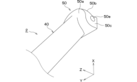
- the tip 50 is located on one side of the handle 2 in the longitudinal direction, and is connected to the support 20 of the razor head 1.
- the outer wall surface 50a of the tip 50 on the grip 40 side is seamlessly continuous with the outer wall surface 401 of the grip 40.
- the outer wall surface 50a is curved such that the radial dimension from the central axis of the handle 2 along the longitudinal direction of the grip 40 gradually increases as it approaches the connection position with the support 20.
- each part where the outer wall surface 50a is connected to the back surface or the underside of the support 20 is seamless. Therefore, the connection part of the handle 2 with the razor head 1 can be made into a rounded shape.
- the connection part which is a place where dirt tends to accumulate, into a curved surface, it is possible to suppress the accumulation of dirt and to make it easier to keep it clean.
- the portion of the tip 50 that is positioned inside the support 20 has a back 50b and a bottom 50c, as shown in Figures 14A and 14B.
- the back 50b is semicircular to correspond to the connecting recess 214 of the back plate 21.
- the bottom 50c is rectangular to correspond to the connecting recess 222 of the housing 22 and the connecting recess 31b of the cover 30.
- the bottom 50c protrudes from one surface 50d of the back 50b that faces the housing 22, and when the tip 50 is connected to the support 20, the back 50b fits into the connecting recess 214, and the bottom 50c fits into the connecting recesses 222, 31b.
- the tip portion 50 is formed with a cylindrical through hole 50e extending in the Y-axis direction.
- the tip portion 50 is connected to the support body 20 by inserting the shaft portion 51 into this through hole 50e and assembling the housing 22 and the back plate 21 so that the shaft portion 51 is supported by the bearing portion 215 of the back plate 21 and the bearing portion 223 of the housing 22.
- a spring hole 50f is formed on one surface 50d of the back portion 50b, into which one end of the spring 25 is inserted.
- the rear end 60 is the portion located on the other side of the handle portion 2 in the longitudinal direction.
- the rear end 60 is a spherical surface whose cross-sectional area gradually decreases the further away from the tip portion 50. Therefore, the rear end 60 also has a rounded shape.
- the razor S is constructed as described above.
- the razor S constructed as described above is used with the blade body 10 and the support 20 covered by the cover 30, as shown in FIG. 1.
- the user When replacing the blade body 10, the user first pinches the second grip 31a with his/her fingers to remove the cover 30 from the support 20 and exposes the blade body 10 to its outer edge, and then pinches the first grip 133 to remove the blade body 10. This allows the blade body 10 to be easily and safely removed from the support 20.
- the blade body 10 is placed on the support surface 220 of the support 20, and the cover 30 is attached to the support 20. This completes the replacement of the blade body 10.
- the frame 13 is magnetically attached or attracted to the mounting surface 220 based on the magnetic force of the magnet 23, and the blade unit 10 is positioned by the retaining piece 229.
- the attachment 33 is magnetically attached to the magnet holder 24 based on the magnetic force of the magnet 23.
- the inner wall surface of the outer peripheral wall 31 abuts against the outer edge of the mounting surface 220, in other words, the outer edge of the housing 22, and the cover unit 30 is attached to the support body 20 without rattling.
- the cover unit 30 is attached to the support body 20
- the cutting edge 11a of the blade 11 in the blade unit 10 is biased toward the inner side of the cover unit 30 by the biasing force of the leaf spring portion 124, thereby suppressing rattling.
- the frame 13 When the blade body 10 is attached to the support 20, the frame 13 may be magnetically attracted directly to the mounting surface 220, but here, as shown in FIG. 15, the leaf spring 124 is in contact with the mounting surface 220 and the frame 13 is separated from the mounting surface 220.
- the blade body 10 When the razor S is in use, the blade body 10 is deflected in the Z-axis direction due to the elasticity of the leaf spring 124, and when a strong force is applied to the blade body 11 that is in contact with the skin, the blade body 10 is displaced toward the inside of the razor head 1, softening the impact of the blade body 11 against the skin.
- the frame 13 is not magnetically attracted directly to the mounting surface 220, but is magnetically attracted at a position away from the mounting surface 220.
- the magnetic attraction force in the latter case may be smaller than the magnetic adhesion force in the former case, but the magnetic attraction force is strong enough to prevent the blade section 10 from falling off the support 20, so the blade section 10 can be attached to the support 20 without any problems.
- the frame 13 may be magnetically attracted directly to the mounting surface 220 if a strong force is applied to the blade 11, the blade section 10 is less likely to be displaced toward the inside of the razor head 1, but the frame 13 may be magnetically attracted directly to the mounting surface 220.
- the leaf spring portion 124 is in contact with the mounting surface 220, and therefore, in this case as well, the blade portion 10 is referred to in this specification as being magnetically attracted to the mounting surface 220.
- the blade unit 10 equipped with the blade 11 is placed on the mounting surface 220 of the support 20 by magnetic attraction, and the cover unit 30 is also attached to the support 20 by magnetic attraction. Then, while the blade unit 10 is sandwiched between the cover unit 30 and the support 20, the cover unit 30 can be removed from the support 20 to replace the blade unit 10.
- the blade body 10 is magnetically attracted to the support 20, the blade body 10 can be magnetically attracted to the support 20 even when the cover 30 is removed, and when removing the blade body 10, it can be easily removed from the support 20 against the magnetic attraction force. Also, by simply bringing the support 20 close to a new blade body 10, the blade body 10 is magnetically attracted to the support 20, and the blade body 10 can be easily replaced. This makes it possible to replace only the blade body 10. And by replacing only the blade body 10, the number of replacement parts can be minimized. Furthermore, because the cover 30 is magnetically attracted to the support 20, the blade body 10 can be clamped between the cover 30 and the support 20, allowing for stable shaving.
- the user's risk of injury from touching the cutting edge 11a or the psychological anxiety that may arise from touching the blade body 10 can be reduced, making it easier for the user to replace the blade body 10.
- a magnet 23 is provided to magnetically attract the blade section 10 and cover section 30 to the support 20, and the magnetic attraction force between the magnet 23 and cover section 30 is stronger than the magnetic attraction force between the magnet 23 and blade section 10.
- the cover section 30 is integrated with the support 20 by a relatively strong magnetic attraction force, and is prevented from becoming detached from the support 20 during shaving.
- the blade section 10 is integrated with the support 20 by a relatively weak magnetic attraction force, so the blade section 10 can be easily removed from the support 20 when replacing it.
- the blade portion 10 When in use, the blade portion 10 is sandwiched between the cover portion 30 and the support 20, and the blade portion 10 will not come off unless the cover portion 30 is removed. Since the cover portion 30 is attracted to the support 20 with a relatively strong magnetic attraction force, the blade portion 10 is also unlikely to come off, allowing the razor S to be used safely. On the other hand, after removing the cover portion 30, the blade portion 10 is attracted to the support 20 with a relatively weak magnetic attraction force, making it easy to remove, and the user can easily remove the blade portion 10.
- the strength of the magnetic attraction force is set by making the distance between the magnet 23 and the part of the blade portion 10 that is magnetically attracted or attracted to the magnet 23 longer than the distance between the magnet 23 and the part of the cover portion 30 that is magnetically attracted to the magnet 23. In this way, the magnetic attraction force can be adjusted simply by varying the distance between the magnet 23 and the cover portion 30 and the distance between the magnet 23 and the blade portion 10, allowing the razor head 1 to have a simple configuration.
- the cover portion 30 is configured to include a cover surface 30a that, together with the support 20, holds the blade portion 10 and an outer peripheral wall 31 that is disposed on the outer edge of the cover surface 30a.
- the outer peripheral wall 31 surrounds the outer edge of the blade portion 10, and the inner wall surface of the outer peripheral wall 31 abuts against the outer edge of the housing 22.
- the blade body 10 is sandwiched between the cover surface 30a and the support 20, while the outer edge of the blade body 10 is surrounded by the outer wall 31, thereby positioning and holding the blade body 10. Furthermore, by configuring the outer wall 31 of the cover 30 to abut against the outer edge of the housing 22, the cover 30 can be positioned and held relative to the support 20. This makes it possible to suppress rattling of the blade body 10 and the cover 30, allowing for more stable shaving.
- the blade portion 10 is provided with a frame 13, which is positioned between the blade 11 and the support 20 to support the blade 11, and the frame 13 is magnetically attached or attracted to the magnet 23.
- the frame 13 is provided with a first gripping portion 133 that protrudes beyond the support 20 in a portion of the razor head 1 that is located opposite the portion where the support 20 is connected to the handle portion 2.
- the blade unit 10 can be magnetically attached to the support 20. Since the frame 13 is provided with the first gripping portion 133, the user can easily remove the blade unit 10 from the support 20 by simply gripping the first gripping portion 133. In addition, since the first gripping portion 133 is arranged on the opposite side of the portion of the razor head 1 where the support 20 is connected to the handle portion 2, the first gripping portion 133 can be arranged in the opposite direction to the direction in which the cutting edge 11a of the blade 11 is pointed. Therefore, even if the user touches the blade 11 when removing the blade unit 10 from the support 20, the user touches it in the opposite direction to the cutting direction, so the user can be protected from injury. This can reduce the psychological anxiety that the user feels that he or she may be injured by touching the blade unit 10, making it easier for the user to replace the blade unit 10.
- the provision of the first gripping portion 133 makes the shape of the blade body portion 10 asymmetrical in the direction in which the multiple blades 11 are arranged, i.e., in the vertical direction, making it easier to determine the orientation when attaching the blade body portion 10 to the support body 20.
- the outer wall 31 of the cover portion 30 also has a second gripping portion 31a that protrudes beyond the support 20 on the side of the razor head 1 opposite the portion where the support 20 is connected to the handle portion 2 and covers the first gripping portion 133.
- the second gripping portion 31a can be gripped separately from the first gripping portion 133, and the cover portion 30 and the blade portion 10 can be removed separately.
- the second gripping portion 31a is positioned on the opposite side of the razor head 1 from the portion where the support 20 is connected to the handle portion 2, the second gripping portion 31a can be positioned in the opposite direction to the direction in which the cutting edge 11a of the blade 11 is pointed. Therefore, even if the user touches the blade 11 when removing the cover portion 30 from the support 20, the touch will be in the opposite direction to the cutting direction, protecting the user from injury.
- the provision of the second gripping portion 31a makes the shape of the cover portion 30 asymmetrical in the vertical direction, making it easier to determine the orientation when attaching the cover portion 30.
- At least the parts of the razor S that are exposed to the outside are entirely made of metal, making it a full metal body.
- the razor S By making the razor S of this kind, it is possible to provide a razor S with a solid feel. Furthermore, for a razor S with a structure in which the blade 11 is exposed from the cover portion 30, the full metal body can be configured with a sense of unity, making it a simple design that is hard to tire of and creating a luxurious product. Furthermore, because the razor S can be made entirely of metal, it is possible to easily separate and dispose of it while also being environmentally friendly.
- the blade portion 10 is replaced when the blade 11 becomes dull, but it is desirable to use the other parts (handle portion 2, cover portion 30, support body 20) for a long period of time without replacing them, thereby reducing waste.
- the other parts handle portion 2, cover portion 30, support body 20
- the product durable and luxurious users will be able to use it for a long time, which will lead to reduced waste.
- the razor head 1 and handle 2 are made entirely of metal to achieve a full metal body, but the type of metal is optional.
- the attachment 33 of the cover 30 and the frame 13 of the blade 10, i.e., the part that is magnetically attached or attracted to the magnet 23, are made of magnetic metal.
- the surfaces of the components that make up the body of the razor S that is, the support 20, the cover portion 30, and the handle portion 2 that are exposed to the outside, are mirror-finished.
- the surfaces that are exposed to the outside are mirror-finished, which gives the razor S a beautiful, bright and lustrous appearance of a metal surface, and also makes it easy to clean and keep clean.
- the razor S has a smooth and pleasant feel to the touch, and even when shaving with the blade 11, the portion of the cover portion 30 where the mirror surface comes into contact with the skin provides a smooth and slippery feel.
- the handle portion 2 has a cross-sectional shape with the longitudinal direction as the normal direction, which is a circle, an ellipse, or a polygon with rounded corners. By making the handle portion 2 in this shape, it is possible to achieve a simpler design and a shape that is easy to grip when in use.
- the handle portion 2 is tapered in such a way that the cross-sectional area gradually decreases from the rear end 60 side opposite the tip portion 50 toward the tip portion 50.
- the connection portion with the razor head 1 can be made thin, while the rear end 60 can be made thicker. This allows the handle portion 2 to have a simple design, while still being easier to grip when in use.
- the center of gravity of the handle portion 2 can be located on the rear end 60 side, the position of the overall center of gravity of the razor S can be shifted from the tip portion 50, where the razor head 1 is attached, toward the rear end 60, allowing for more stable shaving.
- the handle portion 2 is made of solid metal. This gives the razor S a more solid and substantial feel and increases the rigidity of the product. In addition, compared to lighter razors, this allows the user to shave more stably and it is easier to apply pressure, allowing for a closer shave.
- the razor head 1 has an elliptical shape when viewed from the Z-axis direction, and the outer edges of the elliptical shape are rounded in the thickness direction on both the front and back surfaces of the head.
- the cross-sectional shape of the handle portion 2, with the longitudinal direction as the normal direction, is a circle, ellipse, or polygon with rounded corners.
- the razor S can be made to have a rounded shape. This allows the razor S to have a simple, attractive design, and it can be made to have a shape that gives a sense of security, even though it is a blade.
- the razor S also has no rough or bumpy feel, and is comfortable to the touch.
- the rounded shape makes it difficult for dirt to accumulate, and the razor S can be made to have a shape that is easy to keep clean.
- the outer wall surface 50a of the tip 50 is a curved surface whose radial dimension from the central axis of the handle section 2 gradually increases the closer it is to the connection position with the support body 20.
- the razor S is provided with a holder for storing it, making it a razor with a holder, but the rest is the same as the first embodiment, so only the parts that are different from the first embodiment will be described.
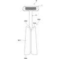
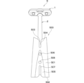
- the holder 500 is a bottomed cylinder having side surfaces 501 and a bottom surface 502, and the handle portion 2 is inserted from the rear end portion 60 side into a hollow portion 503 defined by the side surfaces 501 and bottom surface 502 to house the razor S.
- the holder 500 is a truncated cone shape, and the top side of the truncated cone shape is open to form the hollow portion 503.
- slits 504 formed from the top surface of the holder 500 along the central axis.
- the width of the slits 504 is constant, but gradually widens as it approaches the top surface, so that the top end surfaces of the holder 500 on both sides of the slits 504 are rounded.
- the slits 504 are formed so as to extend from the top surface to the bottom surface, and on the bottom surface side, the width of the slits 504 gradually widens as it approaches the bottom surface, so that the bottom end surfaces of the holder 500 on both sides of the slits 504 are rounded. Furthermore, on the back side of the holder 500, the lower end of the slits 504 is rounded in a semicircular shape. In this way, by forming the slit 504 and rounding the upper and lower end faces of the holder 500 on both sides of the slit 504, it is possible to improve the design while giving it a rounded shape similar to the body of the razor S.
- the slit 504 along the central axis on the front side of the holder 500, it is possible to indicate the insertion direction when inserting the handle portion 2 into the hollow portion 503, and it is also possible to make the entrance of the hollow portion 503 easier to see, making it possible for the user to easily store the razor S in the holder 500.
- part of the side surface 501 is made into a flat surface 505 that is aligned with the insertion direction of the handle portion 2, and a holding magnet 506 is attached to the flat surface 505.
- This holding magnet 506 allows the holder 500 to be magnetically attracted to a magnetic member, so that the holder 500 can be attached to a magnetic member provided on, for example, the wall surface of a bathroom.
- a slit 507 is formed in the center of the flat surface 505, running from the underside of the holder 500 along the central axis.
- the slit 507 gradually widens as it approaches the underside of the holder 500, and the upper lower tip is rounded in a semicircular shape.
- the slit 504 on the front side of the holder 500 and the slit 507 on the back side are connected to the hollow portion 503, so that even if the razor S is stored in the holder 500 in a wet state after use, water can be drained through the slit 504 and slit 507.
- the holder 500 is provided to house the main body of the razor S. Therefore, the razor S can be easily stored by simply inserting it into the holder 500.
- the holder 500 can be installed simply by magnetically attaching the holding magnet 506 to a wall surface or the like made of a magnetic material, and a storage space for the razor S can be secured, so there is no need to secure a storage space above a washroom or the like.
- the holder 500 is installed on a magnetic material by the magnetic attraction force of the holding magnet 506, it can be easily removed and moved, and unlike suction cups whose attraction force can gradually decrease, it can be installed for a long time.
- the razor S is made of a heavy full metal body, it is important to prevent the holder 500 from falling off due to a decrease in attraction force, and preventing it from falling off can ensure safety and security.
- the holder 500 can be given a beautiful, bright and lustrous appearance of a metal surface, and can be constructed to be easy to clean and keep clean. It also feels good to the touch. Furthermore, if the surfaces exposed to the outside of the support 20, cover portion 30, and handle portion 2 are also mirror-finished, it can be made to have a sense of unity with the main body of the razor S, and the design can be further improved.
- a third embodiment will be described.
- a blade container in which a blade body 10 is housed which is suitable for the razor S described in the first and second embodiments, will be described.
- the razor S is similar to that in the first and second embodiments.
- the blade body 10 is stored in a replacement blade storage container 600.
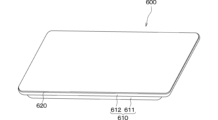
- the replacement blade storage container 600 is composed of a container body 610 and a lid 620.
- the container body 610 has a recess 611 that forms a storage space in which the blade section 10 is stored, and a flange section 612 provided on the opening entrance side of the recess 611.
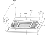
- the recess 611 is deep enough that the blade section 10 does not protrude from the opening entrance, and is deep enough that the support surface 220 of the support 20 of the razor head 1 can contact the blade section 10 when the support 20 is brought close.
- the blade section 10 is stored in this recess 611 with the blade section 11 side facing the bottom side, which is the lower side of the recess 611, and the frame 13 side facing the opening entrance side of the recess 611, which is the upper side.
- the flange section 612 is structured to protrude outward from the recess 611 at the opening entrance of the recess 611, and is flat.
- the lid 620 is attached to the flat flange 612 to cover the blade 10 housed in the recess 611 while sealing the storage space for the blade 10.
- the lid 620 is made of a sheet-like material that is attached to the flange 612 as shown in the figure, or a resin cover with protrusions that fit into the recess 611, and can be easily removed from the flange 612. Note that the figure shows the case where the lid 620 is made of a sheet-like material.
- the blade body 10 stored in such a replacement blade storage container 600 can be used to replace the blade body 10.
- the cover 620 is removed from the flange 612, and the blade body 10 is exposed so that the frame 13 side can be seen from the opening entrance side of the recess 611.
- the frame 13 is magnetically attracted by the magnet 23, and the blade body 10 is attached to the mounting surface 220.
- the cover part 30 is attached to the support 20 to which the blade part 10 is attached, the cover part 30 is magnetically attracted to the magnet 23 and attached to the support 20.
- the blade part 10 is sandwiched between the cover part 30 and the support 20 without any rattling, the razor head 1 is formed, and the replacement of the blade part 10 is completed.
- a replacement blade storage container 600 can be made in which the blade body 10 is stored in the recess 611 of the container body 610 with the frame 13 side facing upward.
- the blade body 10 can be removed simply by removing the lid 620.
- the blade body 10 can be attached to the support 20 simply by magnetically attracting the blade body 10 to the magnet 23 provided on the support 20. This allows the user to easily and safely replace the replacement blade without having to touch it.
- the cost per unit of replacement blades can be reduced compared to replacement blades in which the entire razor head, which has a structure in which the blade body is integrated into a plastic part, is replaced, and the number of products per unit cost can be increased. This means that the frequency with which replacement blades are replaced can be increased, allowing users to shave using newer blades, which can also improve user satisfaction.
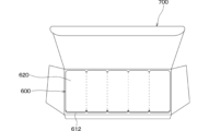
- the blade storage container 600 may have a structure in which a plurality of container bodies 610 are arranged and integrated so that they are connected by flanges 612.
- adjacent container bodies 610 may be made detachable by providing a thin, fragile portion or perforations at the connected portions of the flanges 612.
- container bodies 610 are connected at the flanges 612 and can be separated at the connected parts, they can be separated and used one by one like one-day contact lenses. This makes it possible to carry the required number of replacement blades when traveling or on a business trip. In addition, after the replacement blades have been removed, the container bodies 610 can be separated and disposed of appropriately.
- the blade storage container 600 can be made thin and can be stored in multiple layers in a storage box 700 as shown in Figure 18, making it possible to reduce the storage space required even when storing a large number of blades.
- the gripping portion 40 has a tapered shape in which the cross-sectional area gradually decreases from the rear end 60 to the tip end 50, but the cross-sectional area in the longitudinal direction may be constant.
- one magnet 23 is provided on each of the left and right sides of the support 20.
- the distance between the magnet 23 and the part of the blade section 10 that is magnetically attracted or attracted to the magnet 23 is made different from the distance between the magnet 23 and the part of the cover section 30 that is attracted to the magnet 23.
- this is just one example of making the magnetic attraction force between the magnet 23 and the cover section 30 different from the magnetic attraction force between the magnet 23 and the blade section 10, and other configurations are also possible.
- the part of the magnet 23 that is magnetically attracted to the cover section 30 and the part that is magnetically attracted to the frame 13 may be configured as separate parts with different magnetic attraction forces.
- the magnet 23 is disposed on the support 20 and the magnetic metal is disposed on the cover part 30, but for example, the magnetic metal may be disposed on the support 20 and the magnet on the cover part 30. Furthermore, magnets may be disposed on each of the support 20 and the cover part 30, and the magnets may be disposed so that they attract each other.
- the magnet on the right side of the support 20 is an S pole and the magnet on the left side is an N pole
- the magnet on the right side of the cover part 30 is an N pole and the magnet on the left side is an S pole
- the repulsion of the magnets will prevent the cover part 30 from being attached, and it is possible to prevent the cover part 30 from being attached in the opposite direction.
- the upper surface 34c of the cover part 30 is flat, and the lower surface 34d has a structure in which multiple slots 34e are arranged, but the upper surface 34c may also have a structure in which multiple slots 34e are arranged, and the lower surface 34d may be flat.
- the body may be constructed with resin or the like.
- the back plate 21, housing 22, and cover part 30 of the support 20 of the razor head 1 may be constructed with resin, or the handle part 2 may be constructed with resin.
- the handle part 2 may be constructed with resin.
- a transparent resin is used as the resin, the internal structure of the blade part 10 and the like can be seen, making it possible to show the sense of the internal gimmick.
- the holder 500 is in the shape of a truncated cone, but it can be in the shape of a tube with a bottom, such as a cylindrical tube or a polygonal tube.
- tip portion 50a ...Outer wall surface, 60...Rear end, 121...Installation base, 122...Leg, 123...Support, 124...Leaf spring, 133...First grip, 220...Placement surface, 500...Holder, 501...Side, 502...Bottom, 503...Hollow, 505...Flat surface, 506...Holding magnet, 600...Blade storage container, 610...Container body, 611...Recess, 612...Flange, 620...Lid
Landscapes
- Life Sciences & Earth Sciences (AREA)
- Forests & Forestry (AREA)
- Engineering & Computer Science (AREA)
- Mechanical Engineering (AREA)
- Dry Shavers And Clippers (AREA)
Abstract
剃刀ヘッド1を刃体部10と支持体20およびカバー部30により構成する。刃体部10には、一方向に交差する方向を長尺方向とする刃体11を備える。支持体20は、ハンドル部2の先端部に連結され、刃体11の刃先11aをハンドル部2と連結される側に向けた状態で刃体部10が載置される載置面を備え、磁気吸着にて刃体部10を載置面に載置する。カバー部30は、刃体11を露出させつつ支持体20と共に刃体部10を挟持し、支持体20に対して磁気吸着にて取付けられる。そして、カバー部30が支持体20から取り外されると、刃体部10のみの交換が可能となる。
Description
本開示は、刃体部のみの交換が可能な刃体交換式剃刀(以下、単に剃刀という)および替刃収容容器に関するものである。
従来、特許文献1において、複数の刃を一体とした刃体部のみ交換可能な替刃式剃刀が開示されている。
この替刃式剃刀は、把持部と頭部とを有するホルダと、刃体部を収容する刃台部材および蓋部材を有する剃刀ヘッドと、を備えている。刃台部材および蓋部材は、支持軸によりホルダの頭部の下端に揺動可能に支持されている。蓋部材の上端には係止爪部が配置され、係止爪部が刃台部材の上端に配置された係止軸部に掛け外しされることで、蓋部材と刃台部材との間が開閉可能とさせられている。また、刃台部材の上端には左右両係止爪部が配置され、この左右両係止爪部がホルダの頭部の上端に設けた係止凹部に掛け外しされることで、刃台部材とホルダの頭部との間が開閉可能とされている。さらに、ホルダの頭部の内部に刃体部を磁気吸着する永久磁石が備えられている。
このような構造の替刃式剃刀では、左右両係止爪部を係止凹部から外して刃台部材とホルダの頭部との間を開くと、首振り可能状態となり永久磁石から刃体部から離れる。このため、この状態で係止爪部を係止軸部から外して蓋部材と刃台部材との間を開くと、刃体部を容易に取り外すことができる。また、蓋部材と刃台部材との間を開きつつ、刃台部材とホルダの頭部との間を閉じると、永久磁石が刃体部に当接可能な状態になるため、永久磁石に吸着させることで刃体部を容易に取付けることができる。
しかしながら、上記の替刃式剃刀は、ホルダのヘッドの下端に蓋部材および刃台部材がそれぞれ別々に揺動可能に取付けられ、さらに蓋部材と刃台部材との間の開閉および刃台部材とホルダの頭部との開閉が別々に行える機構が必要になる。このため、剃刀ヘッドの構造が複雑になる。
本開示は、簡素な構造としつつも刃体部のみの交換を可能とする剃刀および替刃収容容器を提供することを目的とする。
上記目的を達成するため、第1の発明は、一方向に沿って伸びるハンドル部(2)と、ハンドル部における一方向の一方側の先端部(50)に取付けられた剃刀ヘッド(1)とを有する剃刀であって、剃刀ヘッドは、一方向に交差する方向を長尺方向とする刃体(11)が備えられた刃体部(10)と、ハンドル部の先端部に連結されており、刃体の刃先(11a)をハンドル部と連結される側に向けた状態で刃体部が載置される載置面(220)を備え、磁気吸着にて刃体部を載置面に載置する支持体(20)と、刃体を露出させつつ支持体と共に刃体部を挟持し、支持体に対して磁気吸着にて取付けられるカバー部(30)と、を有し、カバー部が支持体から取り外されると刃体部のみの交換が可能とされる。
このように、刃体部が支持体に磁気吸着される構造であるため、カバー部が取り外されているときでも支持体に刃体部が磁気吸着されるようにしつつ、磁気吸着力に抗して支持体から刃体部を容易に取り外すことができる。また、新しい刃体部に支持体を近付けるだけで、刃体部が支持体に磁気吸着され、容易に刃体部の交換が行える。これにより、刃体部のみの交換が可能となる。
また、刃体部や刃先に触れる回数を減らすことや、刃体部に触れることなく刃体部の取り付け取外しを行うことができるため、ユーザが刃先に触れて怪我をすることや刃体部に触れることで怪我をするのではないかと感じる心理的不安を低減することができ、ユーザが刃体部の交換をしやすくなる。
さらに、刃体部のみを交換することができるため、必要最小限の交換で済み、廃棄物が少なくなり、SDGsの目標12「つくる責任 つかう責任」のターゲット12.5「2030年までに、廃棄物の発生防止、削減、再生利用及び再利用により、廃棄物の発生を大幅に削減する。」に該当する。
第2の発明では、支持体は、刃体部とカバー部が磁気吸着される磁石(23)を備え、磁石と刃体部との磁気吸着力よりも磁石とカバー部の磁気吸着力の方が強くなっている。このため、カバー部については、比較的強い磁気吸着力で支持体と一体化され、シェービング時に支持体から離れてしまわないようにできる。また、刃体部については、比較的弱い磁気吸着力で支持体に吸着させられるため、交換時に容易に刃体部を支持体から取り外すことができる。
また、使用時、刃体部はカバー部と支持体の間に挟持されており、カバー部が外れなければ刃体部も外れることはなく、カバー部が比較的強い磁気吸着力で吸着されることにより刃体部も外れにくく安全に剃刀を使用することができる。反面、カバー部を外した後は、刃体部は比較的弱い磁気吸吸着力で支持体に吸着されて外しやすくなっており、使用者が刃体部を簡単に外すことができる。
第3の発明では、カバー部のうち磁石に磁気吸着される部分と磁石との間の距離に対して、刃体部のうち磁石に磁気吸着または磁気吸引される部分と磁石との間の距離の方が長くされている。このように、磁石とカバー部との間の距離と磁石と刃体部との間の距離を異ならせるだけで磁気吸着力に強弱を付けられるため、剃刀ヘッドを簡素な構成にできる。
第4の発明では、カバー部は、刃体を露出させる窓部(35)が形成され、載置面に対向し、支持体と共に刃体部を挟持するカバー面(30a)と、カバー面の外縁に配置され、刃体部の外縁を囲むと共に支持体における載置面の外縁に当接する外周壁(31)と、を有している。
このように、カバー面と支持体とによって刃体部を挟持しつつ、外周壁で刃体部の外縁を囲むことで、刃体部を位置決めして保持できる。また、カバー部の外周壁が載置面の外縁に当接する構成とすることで、カバー部を支持体に対して位置決めして保持できる。これにより、刃体部やカバー部のガタつきを抑制でき、より安定したシェービングが可能になる。
第5の発明では、刃体部は、長尺方向に対して直交する方向に複数枚並べられた刃体と、刃体と支持体との間に配置され、刃体を支持すると共に磁石に磁気吸着または磁気吸引されるフレーム(13)と、刃体とフレームとの間に配置され、刃体およびフレームと一体化される刃台部材(12)と、を有して構成されている。このような構成によれば、フレームを磁石に磁気吸着または磁気吸引すれば刃体部を支持体に磁気吸着できる。
第6の発明では、剃刀ヘッドのうち支持体がハンドル部に連結されている部分と反対側に位置する部分において、フレームには支持体よりも突出した第1摘まみ部(133)が備えられている。このように、フレームに第1摘まみ部を備えているため、ユーザが第1摘まみ部を摘まむだけで容易に支持体から刃体部を取り外せる。また、第1摘まみ部の配置を剃刀ヘッドのうち支持体がハンドル部に連結されている部分と反対側としているため、刃体の刃先が向けられる方向と逆方向に第1摘まみ部を配置できる。このため、刃体部を支持体から取り外す際に、ユーザが刃体に触れても切断方向と逆方向で触れることになるため、ユーザを怪我から守ることができる。そして、怪我をすることや刃体部に触れることで怪我をするのではないかと感じる心理的不安を低減することができ、ユーザが刃体部の交換をしやすくなる。
第7の発明では、剃刀ヘッドのうち支持体がハンドル部に連結されている部分と反対側に位置する部分において、カバー部の外周壁には支持体よりも突出し、第1摘まみ部を覆う第2摘まみ部(31a)が備えられている。このように、第1摘まみ部を覆うように第2摘まみ部を設けることで、第2摘まみ部を第1摘まみ部とは別に摘まむことができ、カバー部の取り外しと刃体部の取り外しを別々に行うことができる。また、第2摘まみ部の配置場所についても、剃刀ヘッドのうち支持体がハンドル部に連結されている部分と反対側とすれば、刃体の刃先が向けられる方向と逆方向に第2摘まみ部を配置できる。このため、カバー部を支持体から取り外す際に、ユーザが刃体に触れても切断方向と逆方向で触れることになるため、ユーザを怪我から守ることができる。
第8の発明では、カバー部と刃体部のうち磁石に磁気吸着される部分が磁性金属製とされていることに加えて、剃刀ヘッドおよびハンドル部がすべて金属製とされている。このように、フルメタルボディとすることで、重厚感のある剃刀を提供できる。また、カバー部から刃体を露出させる構造の剃刀において、フルメタルボディという統一感のある構成にでき、デザイン的にもシンプルで飽きにくく、高級感のある製品にできる。また、例えば、刃体部は刃体の切れ味が悪くなった場合は交換するが、それ以外の部分(ハンドル部、カバー部、支持体)は交換せず長期にわたり使用することで廃棄物を抑制することが望まれる。このため、金属によって各部品の耐久性を向上させることに加え、飽きにくく高級感のある製品にすることで、ユーザに長く使用してもらうことができ、廃棄物の抑制につながる。
第9の発明は、第5ないし7のいずれか1つ発明の刃体交換式剃刀に用いられる刃体部が収容された替刃収容容器であって、刃体部が収容される凹部(611)と、該凹部の周囲に突出した平面状のフランジ部(612)と、を有する容器本体部(610)と、凹部内に収容された刃体部を覆いつつフランジ部に取付けられ、フランジ部から取り外されることで刃体部の取り出しを可能とする蓋部(620)と、を備え、刃体側が凹部の底面側に向けられ、フレーム側が凹部の底面と反対側に向けられて、刃体部が凹部に収容されている。
このような替刃収容容器とすれば、蓋部を取り外すだけで刃体部を取り出せる。また、容器本体部の凹部内に刃体部を配置したままの状態で支持体に備えた磁石に刃体部を磁気吸引させるだけで刃体部を支持体に取付けることができる。このため、ユーザは替刃に触れなくても容易かつ安全に替刃交換を行うことができる。
また、刃体部や刃先に触れる回数を減らすことや刃体部に触れることなく、刃体部の取り付け取外しを行うことができるため、ユーザが刃先に触れて怪我をすることや刃体部に触れることで怪我をするのではないかと感じる心理的不安を低減することができ、ユーザが刃体部の交換をしやすくなる。
第10の発明では、容器本体部は、複数個がフランジ部において連結されていると共に、該連結された箇所で切り離し可能とされている。このような構造とすれば、替刃収容容器を1dayコンタクトレンズのように1つ1つ切り離して使用できる。また、替刃収容容器を薄型化できると共に収容ボックスなどに複数段重ねて保管することもでき、替刃を多数保管しても保管スペースを少なくすることが可能となる。
なお、各構成要素等に付された括弧付きの参照符号は、その構成要素等と後述する実施形態に記載の具体的な構成要素等との対応関係の一例を示すものである。
以下、本開示の実施形態について図に基づいて説明する。なお、以下に説明する他の実施形態を含めて、各実施形態相互において、互いに同一もしくは均等である部分には、同一符号を付して説明を行う。
(第1実施形態)
以下、図1~図15を参照して本開示の第1実施形態にかかる剃刀Sについて説明する。
以下、図1~図15を参照して本開示の第1実施形態にかかる剃刀Sについて説明する。
〔剃刀Sの構成〕
図1~図5に示す剃刀Sは、剃刀ヘッド1とハンドル部2とを有して構成され、ムダ毛のシェービングに使用される。本実施形態の剃刀Sは、少なくとも外部に露出している部品が全て金属製とされたフルメタルボディとされており、ここでは外部に露出する表面が鏡面仕上げされたボディとされている。
図1~図5に示す剃刀Sは、剃刀ヘッド1とハンドル部2とを有して構成され、ムダ毛のシェービングに使用される。本実施形態の剃刀Sは、少なくとも外部に露出している部品が全て金属製とされたフルメタルボディとされており、ここでは外部に露出する表面が鏡面仕上げされたボディとされている。
なお、本明細書に添付した図面中に、X軸、Y軸およびZ軸を示している。剃刀ヘッド1を正面から見た剃刀ヘッド1の上下方向をX軸、X軸と直交する剃刀ヘッド1の幅方向をY軸、X軸およびY軸に対して直交する剃刀ヘッド1の厚み方向をZ軸と呼ぶ。また、剃刀Sのうちの剃刀ヘッド1側を剃刀Sの先端、その反対側を剃刀Sの後端と呼ぶ。また、図2のうちY軸に沿う右側と左側をそれぞれ剃刀Sの右側、左側と呼び、X軸方向に沿う上側と下側をそれぞれ剃刀Sの上側、下側と呼ぶ。さらに、図2のうちZ軸に沿う紙面手前側、つまり図2に表されている側を剃刀Sの表側、その反対側となる紙面向こう側を剃刀Sの裏側と呼ぶ。また、以下に説明する剃刀Sの各構成要素についても、剃刀Sの右側、左側、上側、下側、表側、裏側それぞれに対応する方を各構成要素の右側、左側、上側、下側、表側、裏側と言う。
〔剃刀ヘッド1の構成〕
剃刀ヘッド1は、剃刀Sにおけるシェービングを行う刃部を構成する部分である。剃刀ヘッド1は、全体として、X軸方向を短軸、Y軸方向を長軸とした長円形状とされ、Z軸方向の寸法として所定の厚みを有した構造とされる。そして、剃刀ヘッド1の表側となるヘッド表面とその反対側となるヘッド裏面の両方共に、剃刀ヘッド1の厚み方向となるZ軸方向において、長方形状の外縁が丸まった形状とされている。このため、剃刀ヘッド1は、刃部を構成しつつも、丸みを帯びた形状とされている。具体的には、剃刀ヘッド1は、刃体部10と支持体20およびカバー部30を備える。
剃刀ヘッド1は、剃刀Sにおけるシェービングを行う刃部を構成する部分である。剃刀ヘッド1は、全体として、X軸方向を短軸、Y軸方向を長軸とした長円形状とされ、Z軸方向の寸法として所定の厚みを有した構造とされる。そして、剃刀ヘッド1の表側となるヘッド表面とその反対側となるヘッド裏面の両方共に、剃刀ヘッド1の厚み方向となるZ軸方向において、長方形状の外縁が丸まった形状とされている。このため、剃刀ヘッド1は、刃部を構成しつつも、丸みを帯びた形状とされている。具体的には、剃刀ヘッド1は、刃体部10と支持体20およびカバー部30を備える。
〔刃体部10の構成〕
刃体部10は、剃刀Sにおいて交換可能な部品であり、図6~図9に示すように刃体11と刃台部材12およびフレーム13によって構成されている。これら刃体11、刃台部材12およびフレーム13は、すべて金属で構成されている。
刃体部10は、剃刀Sにおいて交換可能な部品であり、図6~図9に示すように刃体11と刃台部材12およびフレーム13によって構成されている。これら刃体11、刃台部材12およびフレーム13は、すべて金属で構成されている。
刃体11は、図8Aに示すように、Y軸方向を長尺方向とする長方形状で構成され、長尺方向に直交するX軸に対して所定角度傾けられた状態で、X軸方向に沿って複数枚、ここでは5枚並べられて配置されている。各刃体11には刃先11aが形成されており、図1に示すように、各刃体11の刃先11aがハンドル部2と連結される側となる下側に向けられ、かつ各刃先11aが等間隔に並ぶようにして複数枚の刃体11が配置されている。このため、剃刀ヘッド1を下側に向けて移動させることでシェービングを行うことができる。以下、このシェービングを行う際に剃刀ヘッド1を移動させる方向、つまり下側の方向ことをシェービング方向とも言う。
刃台部材12は、複数枚の刃体11を溶接などにより接合して一体化する部材である。刃台部材12は、バネ構造を備え、このバネ構造による弾性力に基づいて、シェービング時の肌への当たりを和らげており、支持体20とカバー部30との間に刃体部10を挟持した際の刃体部10のガタつき防止も行っている。図8A、図8B、および図9Bに示すように、刃台部材12は、設置台部121、脚部122、支持部123および板バネ部124を有する。
設置台部121は、複数枚の刃体11が設置される基台であり、階段状に配置された複数の接合部121aを備え、その複数の接合部121aを支持部123で連結した構造とされる。各接合部121aは、Y軸に沿って延設され、刃体11と対応する直線状とされている。そして、各接合部121aは、刃体11の接合面となる表面が平坦面とされており、その表面が互いに平行となるようにしてX軸方向に並べられている。各接合部121aの表面は、XY平面に対して傾斜しており、各接合部121aに対して1枚ずつ刃体11が点溶接されることで、各刃体11がXY平面に対して傾斜した状態で設置台部121に一体化されている。
脚部122は、Y軸に沿って配置された直線状の部材であり、設置台部121を挟んだ上下両側に配置され、各接合部121aと同様Y軸に沿って延設されている。各脚部122は、Z軸方向において設置台部121よりもフレーム13側に位置しており、各脚部122のY軸方向の両端には、板バネ部124が接続されている。
支持部123は、各接合部121aや各脚部122に交差するようにX軸方向に伸び、各接合部121aおよび各脚部122を連結している。支持部123は、複数本、ここでは4本備えられ、そのうちの内側の2本がフレーム13のうちの後述する第1枠体部131と対応した位置に配置されている。支持部123は、各接合部121aが階段状に並ぶように屈曲させられており、各脚部122に接続される部分において各接合部121aよりも各脚部122が裏側に位置するように屈曲させられている。
板バネ部124は、各脚部122の両端を刃体11と反対側に屈曲させられて構成されている。板バネ部124は、Z軸方向に力が加えられると、弾性変形して弾性反力を発生させる。板バネ部124の先端は、フレーム13の裏側に突き出させてあり、刃体部10を支持体20に取付けると板バネ部124の先端が支持体20の載置面220に接触する。
なお、刃台部材12は、例えば板状金属をプレス加工することで形成される。図8Bに示すように、各接合部121aの間は支持部123にて連結されているが、各接合部121aの間のうちの支持部123と異なる場所は打ち抜きおよび裏側に折曲げた折曲部121bとして接合部121aに繋げたまま残せば、接合部121aを補強できる。この場合でも、支持部123をフレーム13の第1枠体部131と対応した位置に形成すれば、折曲部121bがフレーム13と干渉しないようにできる。
フレーム13は、刃体11および刃台部材12を保持すると共に、後述する支持体20に磁気吸着もしくは磁気吸引される部分である。図8B、図9Cに示すように、フレーム13は、第1枠体部131と第2枠体部132とを有している。これら第1枠体部131と第2枠体部132は一体化された一部品とされ、表側と裏側が共に平面状とされていて、例えば板状金属の打ち抜きや金属成形により形成されている。
第1枠体部131は、四角枠体形状とされ、刃台部材12が接合される部分である。具体的には、第1枠体部131は、Y軸方向に沿った一方の相対する二辺を構成する上梁部131aおよび下梁部131bと、X軸方向に沿ったもう一方の相対する二辺を構成する右梁部131cおよび左梁部131dとにより構成されている。上梁部131aおよび下梁部131bの表面に各脚部122が接合されると共に、右梁部131cおよび左梁部131dの上に支持部123が配置されるようにしてフレーム13に刃台部材12が固定され、刃台部材12を介して刃体11もフレーム13に固定されている。
第2枠体部132は、長円枠体形状とされ、内側に第1枠体部131が連結されている。具体的には、第2枠体部132は、上梁部132aおよび下梁部132bと、右半円梁部132cおよび左半円梁部132dとにより構成され、上梁部132aおよび下梁部132bが第1枠体部131の上梁部131aおよび下梁部131bとそれぞれ連結され、右半円梁部132cや左半円梁部132dがそれぞれ第1枠体部131の右梁部131cや左梁部131dの外方に張り出して配置されている。第2枠体部132は、ほぼ長円枠体形状とされているが、上梁部132aの中央位置において、第1枠体部131と反対側の外方に向って突出していて、この突出した部分によって第1摘まみ部133が構成されている。
なお、第1枠体部131の内側には開口部134、右梁部131cと右半円梁部132cとの間には開口部135、左梁部131dと左半円梁部132dとの間には開口部136が形成されている。これらの開口部134~136が形成されていることにより、折曲部121bとフレーム13との干渉が抑制される。
〔支持体20の構成〕
支持体20は、図10に示すようにハンドル部2の一端に連結され、刃体部10およびカバー部30を支持する部品である。支持体20は、表側から視た形状がほぼ長円形状をなしており、長軸方向がY軸方向に沿い、短軸方向がX軸方向に沿って配置されている。そして、長円形状のうちの下側の一辺の中央位置において、ハンドル部2と連結されている。具体的には、支持体20は、図6、図7に示すように背面板21、ハウジング22、磁石23、磁石ホルダ24、バネ25およびネジ26を有している。なお、支持体20は、剃刀Sのボディを構成する部品の1つであり、支持体20を構成する部分のうち外部に露出する部分となる背面板21、ハウジング22などは金属製とされ、外部に露出する表面は鏡面とされている。
支持体20は、図10に示すようにハンドル部2の一端に連結され、刃体部10およびカバー部30を支持する部品である。支持体20は、表側から視た形状がほぼ長円形状をなしており、長軸方向がY軸方向に沿い、短軸方向がX軸方向に沿って配置されている。そして、長円形状のうちの下側の一辺の中央位置において、ハンドル部2と連結されている。具体的には、支持体20は、図6、図7に示すように背面板21、ハウジング22、磁石23、磁石ホルダ24、バネ25およびネジ26を有している。なお、支持体20は、剃刀Sのボディを構成する部品の1つであり、支持体20を構成する部分のうち外部に露出する部分となる背面板21、ハウジング22などは金属製とされ、外部に露出する表面は鏡面とされている。
背面板21は、剃刀ヘッド1の裏側となるヘッド裏面を構成する部分である。図11Aに示すように、背面板21は、表側から視た外形形状がほぼ長円形状とされている。背面板21は、長円形状の外縁に沿う外周壁211を備え、この外周壁211の内側において表側から裏側に向って長円形状に凹んだ凹部212が形成されている。この凹部212には、ハウジング22の一部などが配置される。
背面板21のうちの上側の中央位置には、外周壁211が一部切り欠かれて溝部213が構成されている。この溝部213は、上記したフレーム13の第1摘まみ部133や後述するカバー部30の第2摘まみ部31aと対応した位置に形成され、図5に示すように剃刀ヘッド1を裏側から見ると、溝部213から第1摘まみ部133と第2摘まみ部31aが突き出すサイズとされている。
また、背面板21のうちの下側の中央位置にも、外周壁211が一部切り欠かれて半円状の連結凹部214が形成されている。この連結凹部214などに、ハンドル部2の先端が配置されて、支持体20とハンドル部2との連結がなされている。支持体20をハンドル部2に固定して剃刀ヘッド1がハンドル部2に対して首振りできない固定ヘッド構造としも良いが、本実施形態では、剃刀ヘッド1がハンドル部2に対して首振り可能な首振りヘッド構造とされている。具体的には、図11A、図11Bに示すように連結凹部214の左右両側に一対の軸受部215を配置している。図6、図7に示された後述するハンドル部2の先端に取付けられる軸部51が軸受部215に嵌め込まれ、軸部51を中心とした軸周りに、剃刀ヘッド1がハンドル部2に対して首振り可能になっている。連結凹部214の上端壁214aは、凹部212の底面から突出しており、ハンドル部2の先端形状に対応した形状とされている。
連結凹部214の左右両側において、軸受部215の上側には、一対の円筒状の雌ネジ部216が備えられている。また、一対の雌ネジ部216を挟んだ左右両側に磁石23の座部217が形成されている。座部217は、その周囲が部分的に凹部212の底面より凹まされることで周囲よりも突出した形状とされている。さらに、左右両側の各雌ネジ部216と各座部217との間には、背面板21の表裏を貫通する貫通孔218が形成されている。
一方、ヘッド裏面を構成する背面板21の裏側は、剃刀ヘッド1の厚み方向となるZ軸方向において、長円形状の外縁が丸まった形状とされている。
ハウジング22は、背面板21と連結されて、背面板21と共に支持体20の外形形状を構成する部品であり、支持体20の内部に磁石23や後述するハンドル部2の先端部50などを収容するために背面板21とは別部品とされている。
図12Aに示すように、ハウジング22のうちの表側の一面を載置面220として、刃体部10が載置される。ハウジング22も、表側から視た外形形状がほぼ長円形状とされている。長円形状の長軸および短軸のサイズは背面板21の凹部212と対応するサイズとされている。ハウジング22のうちの上側の中央位置には、ハウジング22の外縁の壁面が一部切り欠かれて溝部221が形成されている。この溝部221は、背面板21に形成された溝部213と対応する位置および形状とされ、図5に示すように剃刀ヘッド1を裏側から見ると、溝部213から第1摘まみ部133と第2摘まみ部31aが突き出すサイズとされている。
また、ハウジング22のうちの下側の中央位置にも、ハウジング22の外縁の壁面が一部切り欠かれて、ハンドル部2の先端部50が配置される長方形状の連結凹部222が形成されている。図12Bに示すように、ハウジング22の裏側において、連結凹部222の左右両側には、背面板21の軸受部215と対応する位置に一対の軸受部223が配置されている。この軸受部223にも、ハンドル部2の先端部50に取付けられる軸部51が嵌め込まれ、上記した首振りヘッド構造が実現される。
ハウジング22の裏側における連結凹部222よりも上方位置には、ハウジング22の裏側から表側に向けて凹む凹部224が形成されている。凹部224は、背面板21における連結凹部214の上端壁214aや雌ネジ部216と対応する形状とされ、雌ネジ部216と対応する位置には一対の貫通孔224aが形成されている。そして、貫通孔224aは載置面220まで達しており、図12Aに示すように、載置面220のうちの貫通孔224aの周囲には、ザグリ225が形成されている。さらに、図12Bに示すように、凹部224の底面における連結凹部222の上側には、円柱状突起のバネ取付部226が形成され、このバネ取付部226にバネ25が嵌め込まれる。
また、ハウジング22のうち一対の貫通孔224aを挟んだ左右両側には磁石23および磁石ホルダ24が収容される一対の収容部227が形成されている。この収容部227内に磁石23などが配置されることで、支持体20に対して刃体部10やカバー部30が磁気吸着される。
各収容部227は、略長方体形状に凹んだ形状とされている。各収容部227が形成された位置において、ハウジング22の肉厚が変化させられている。具体的には、Z軸方向から視て、各収容部227のうちハウジング22の内側に位置していて載置面220と重なっている部位22aは、載置面220の外側に位置する部位22bと比較してハウジング22の肉厚が厚くされている。本実施形態の場合、部位22aはハウジング22の肉が残されており、部位22bはハウジング22の肉がない状態とされているが、部位22bに肉が残されていても良い。
部位22aにおける表側の一面は、載置面220の一部を構成しており、刃体部10、具体的にはフレーム13が磁気吸着または磁気吸引される場所になる。部位22bは、カバー部30が磁気吸着される場所になる。部位22aでは、部位22bよりもハウジング22の肉厚が厚くされている。これにより、刃体部10のうち磁石23に磁気吸着または磁気吸引される部分と磁石23との間の距離の方が、カバー部30のうち磁石23に磁気吸着される部分と磁石23との間の距離より長くなる。このため、磁石23と刃体部10との磁気吸着力よりも磁石23とカバー部30との磁気吸着力の方が強くなる。
さらに、左右両側の各貫通孔224aと各収容部227との間には、ハウジング22の表裏を貫通する貫通孔228が形成されている。この貫通孔228は、背面板21に形成された貫通孔218と対応する位置および形状とされ、貫通孔218と繋がって剃刀ヘッド1の内外を連通させる。このため、剃刀ヘッド1を水洗いすると、貫通孔218、228を通じて、剃刀ヘッド1の内側の汚れや水を排出させられる。
また、ハウジング22の表側において、載置面220の四隅であって収容部227よりもX軸方向の外側の位置に、載置面220から突出した保持片229が形成されている。保持片229は、載置面220と接する内壁面229aが円弧状の曲面とされ、フレーム13の位置決めを可能としている。
磁石23は、永久磁石で構成され、図6、図7に示すように長方体形状とされていて収容部227と対応するサイズとされている。磁石23の材質については任意であるが、合金磁石などを用いれば磁石23も金属製にでき、ここでは磁石23も金属製としている。
磁石ホルダ24は、必要に応じて備えられるもので、磁石23の周囲を囲むように配置され、図6、図7に示すようにX軸方向から見てU字状とされている。磁石23を磁石ホルダ24で囲んだ状態で収容部227に収容することで、ハウジング22に対する磁石23のガタつきを抑制している。
バネ25は、圧縮コイルバネとされ、バネ取付部226に取付けられる。バネ25は、ハウジング22における凹部224の底面とハンドル部2の先端部50との間に配置され、圧縮反力によりハンドル部2の先端部50を付勢している。これにより、剃刀Sの右側から視て、剃刀ヘッド1に対して軸部51を中心とした時計回りにハンドル部2が付勢される。ハンドル部2の先端部50のうちハウジング22の連結凹部222に配置される後述する底部50cが連結凹部222の底面と当接する位置を初期位置として、剃刀ヘッド1に荷重が掛っていない状態ではバネ25の圧縮反力によってハンドル部2が初期位置に位置した状態となる。そして、シェービング時に剃刀ヘッド1に荷重が加わり、剃刀Sの右側から視て、剃刀ヘッド1に軸部51を中心とした時計回りのモーメントが加わると、バネ25の圧縮反力に抗して剃刀ヘッド1が首振りを行う。
ネジ26は、ハウジング22と背面板21とを一体化する役割を果たす。ネジ26が貫通孔224aを通じて雌ネジ部216に締結されることで、ハウジング22が背面板21に固定されている。載置面220のうちの貫通孔224aの周囲にザグリ225が形成されているため、ネジ26の頭がザグリ225内に入り込み、ネジ26の突き出しが抑制されている。
〔カバー部30の構成〕
カバー部30は、図1に示すように、中央位置において刃体11の刃先11aを露出させつつ、刃体部10の外縁部を覆う部品である。カバー部30にて刃体部10の外縁やハウジング22の外縁を囲むようにして、カバー部30を支持体20に取付けることで、剃刀ヘッド1が構成される。なお、カバー部30は、剃刀Sのボディを構成する部品の1つであり、金属製とされ、外部に露出する表面は鏡面とされている。
カバー部30は、図1に示すように、中央位置において刃体11の刃先11aを露出させつつ、刃体部10の外縁部を覆う部品である。カバー部30にて刃体部10の外縁やハウジング22の外縁を囲むようにして、カバー部30を支持体20に取付けることで、剃刀ヘッド1が構成される。なお、カバー部30は、剃刀Sのボディを構成する部品の1つであり、金属製とされ、外部に露出する表面は鏡面とされている。
図2に示すように、カバー部30は、表側から見た形状がほぼ長円形状とされている。カバー部30のうちのおもて面を構成する壁面をカバー面30aとして、このカバー面30aの表面によりヘッド表面が構成されている。カバー部30は、図13Aに示すように長円形状の外縁に沿う外周壁31を備え、図13Bに示すように外周壁31の内側において裏側から表側に向って長円形状に凹んだ凹部32が形成されている。カバー面30aの裏面によって凹部32の底面が構成され、外周壁31によって凹部32の内壁面が構成されている。この凹部32に、刃体部10やハウジング22の一部などが配置される。凹部32内の形状は、刃体部10やハウジング22の形状に対応させられている。このため、カバー部30を支持体20に対して、ガタつきなく取付けられる。また、カバー部30を支持体20に取付けた際に、カバー部30のうちのカバー面30aの裏面と支持体20とによって刃体部10が挟持される。さらに、カバー部30を支持体20に取付けた際に、凹部32の底面の一部が刃体11の両端に当接し、刃体部10をハウジング22側に押す荷重が加えられるようになっている。このため、カバー部30を支持体20に取付けた際に、板バネ部124の弾性力や刃体部10の各部の撓みにより、刃体部10のガタつきも抑制される。
また、凹部32内におけるY軸方向の両端には、座部32aが備えられている。座部32aには、図6、図7に示すアタッチメント33が固定される。アタッチメント33は、磁石23に磁気吸着される部分である。カバー部30を支持体20に取付けた際に、アタッチメント33がハウジング22のうちの部位22bにおいて、磁石23に磁気吸着される。カバー部30が磁性金属製の場合には、アタッチメント33を備えなくても座部32aが磁石23に直接磁気吸着されるようにできる。ただし、アタッチメント33を取付ければ、アタッチメント33を介して座部32aが磁石23に磁気吸着されるため、カバー部30が磁性金属でなくてもよくなる。
座部32aは、凹部32の底面を部分的に突き出させることで構成されており、各座部32aを覆うように1つずつアタッチメント33が配置される。各アタッチメント33は、YZ平面で切断した断面がV字状の部材とされ、XZ平面に沿う内壁面33aと、XY平面に沿い座部32aの先端に配置される吸着面33bとを有した構成とされている。そして、カバー部30を支持体20に取付けると、吸着面33bが磁石23に磁気吸着されることでカバー部30が支持体20に一体化される。Y軸方向において、両アタッチメント33の間隔は載置面220やフレーム13の寸法に揃えられており、カバー部30を支持体20に取付けた際に両アタッチメント33の間に載置面220および刃体部10が配置される。
カバー面30aのうちの表側は肌接触面34となる部分である。この肌接触面34が剃刀Sによるシェービング時にユーザの肌に接する。肌接触面34には、カバー部30の表側から裏側に貫通し、Y軸方向を長手方向とする略長方形の窓部35が形成されている。この窓部35を通じて、刃体11がカバー部30から露出させられている。また、肌接触面34のうち窓部35を挟んだ上下方向の両側において、肌接触面34を凹ませた凹部34aが形成されている。肌接触面34のうち窓部35および凹部34aを挟んだ左右方向の両側は、半円状の平坦面34bとされている。凹部34aを形成することで、刃体11の刃先11aが凹部34aの底面から表側に突き出させられ、深剃りを可能としている。また、刃体11の両端が平坦面34bによって覆われ、シェービング時に刃体11の両端がユーザの肌に引っ掛かることが抑制されている。
なお、肌接触面34の凹部34aの底面について、窓部35より上側、つまりシェービング方向の後方側に位置する上側面34cについては平坦面としている。また、窓部35より下側、つまりシェービング方向の前方側に位置する下側面34dについてはX軸方向に伸びるスロット34eをY軸方向に複数本並べた構造としている。このため、下側面34dについては、スロット34eを形成している分、肌との接触面積が減って肌の引っ付きが抑制されると共に、スロット34e内にシェービングクリームや水分が入り込むことで、より円滑なシェービングが可能となる。また、上側面34cについては、平坦面とされることで滑らかな肌触りを実現できる。
上記したように、カバー部30は、表側から見た形状がほぼ長円形状とされているが、剃刀ヘッド1の厚み方向となるZ軸方向において、長円形状の外縁が丸まった形状とされている。より詳しくは、カバー部30の表側における平坦面34bよりも外側や凹部34aよりも外側において、カバー部30の外縁が厚み方向において丸められている。
さらに、A、図13Bに示すように、カバー部30の上側における外周壁31の中央位置において、外周壁31が上側に向って突出しており、この突出した部分によって第2摘まみ部31aが構成されている。図13Bに示すように、第2摘まみ部31aにおいて、外周壁31の内側の壁面、つまり凹部32側の壁面も上側に湾曲させられていて、凹部32内の空間が広げられており、この空間内に刃体部10の第1摘まみ部133が収容される。また、第2摘まみ部31aは、カバー部30の他の部位よりも裏側に突き出している。この部分がハウジング22の溝部221や背面板21の213に入り込む。
また、カバー部30のうちの下側の中央位置にも、外周壁31が一部切り欠かれて半円状の連結凹部31bが形成されている。この連結凹部31bに、他の連結凹部214、222などと共に、ハンドル部2の先端部50が配置されて、支持体20とハンドル部2との連結がなされている。
〔ハンドル部2の構成〕
ハンドル部2は、剃刀Sを使用する際にユーザが把持する部分である。ハンドル部2は、剃刀Sのボディを構成する部分の1つであり、金属製とされ、外部に露出する表面は鏡面とされている。具体的には、ハンドル部2は、一方向を長手方向とする棒状部材で構成され、把持部40と、把持部40の上端側に位置する先端部50と、把持部40の下端側に位置する後端部60を有している。
ハンドル部2は、剃刀Sを使用する際にユーザが把持する部分である。ハンドル部2は、剃刀Sのボディを構成する部分の1つであり、金属製とされ、外部に露出する表面は鏡面とされている。具体的には、ハンドル部2は、一方向を長手方向とする棒状部材で構成され、把持部40と、把持部40の上端側に位置する先端部50と、把持部40の下端側に位置する後端部60を有している。
把持部40は、先端部50と後端部60との間に位置する棒状の部分であり、ハンドル部2の長手方向を法線方向とする断面形状が正方形を含む長方形の各角部を丸めた形状とされている。把持部40の長手方向に沿う中心軸は、XY平面に平行な剃刀ヘッド1の裏面に対して所定角度傾斜させられており、剃刀ヘッド1が首振りを行うと首振り量に応じてその角度が変化する。把持部40については、任意の形状にでき、直線状の棒状部材の他、長手方向の中間位置が他の部位と比較して膨らんだ形状とされていたり、屈曲した形状とされていたり、長手方向の中間位置に凹みや開口部が形成された形状とされていても良い。ただし、一方向を法線方向とする断面形状が円形や楕円形もしくは多角形の各角部を丸めた直線状の棒状部材で把持部40を構成すると、よりシンプルかつシャープなデザインにでき、使用時に把持しやすい形状にできる。
把持部40は、後端部60から先端部50に向って断面積が徐々に縮小するテーパ形状とされている。このため、把持部40のうち剃刀ヘッド1との連結部側を細くしつつも、後端部60側を太くした尻太の形状にできる。したがって、シンプルなデザインとしつつも、より使用時に把持しやすい形状にできる。また、ハンドル部2の重心を後端部60側にできるため、剃刀Sの全体の重心位置を剃刀ヘッド1の取付けられる先端部50から後端部60側に寄せることができ、安定したシェービングが可能になる。
また、把持部40は、中身が詰まった中実の金属とされている。このため、剃刀Sの重量を大きくでき、剃刀Sによりズッシリとした重厚感を持たせられると共に、製品の剛性を高めることが可能となる。また、ユーザが剃刀Sを使用する際に、重量が小さくされた場合と比較して安定したシェービングが可能となり、かつシェービング時に荷重が加えやすくなるため、より深剃りが可能となる。
先端部50は、ハンドル部2の長手方向の一方側に位置し、剃刀ヘッド1における支持体20と連結される部分である。図3~図5に示すように、先端部50のうち把持部40側の外壁面50aは、把持部40の外壁面401に対して継ぎ目なく連続している。そして、先端部50のうちの支持体20と連結される部位において、外壁面50aは、支持体20との連結位置に近づくほど、把持部40の長手方向に沿うハンドル部2の中心軸からの径方向寸法が徐々に拡大する曲面とされている。そして、外壁面50aと支持体20の裏面や下面とが繋がる各部において、繋ぎ目ない形状になっている。このため、ハンドル部2における剃刀ヘッド1との連結部について、丸みを帯びた形状にできる。加えて、連結部という汚れが溜まりやすい場所を曲面とすることで、汚れが溜まることを抑制でき、より清潔に保ちやすい形状にできる。
先端部50のうち、支持体20の内側に配置される部分は、図14A、図14Bに示すように背部50bと底部50cとを有した構成とされている。背部50bは、背面板21の連結凹部214と対応する半円状とされている。底部50cは、ハウジング22の連結凹部222やカバー部30の連結凹部31bと対応する四角形状とされている。背部50bのうちのハウジング22側の一面50dから底部50cが突き出して配置され、先端部50を支持体20に連結すると、背部50bが連結凹部214に嵌まり、底部50cが連結凹部222、31bに嵌まる。
先端部50には、Y軸方向に伸びる円柱形状の貫通孔50eが形成されている。この貫通孔50eに軸部51を挿通させ、軸部51が背面板21の軸受部215とハウジング22の軸受部223に支持されるように、ハウジング22と背面板21とを組付けることで、先端部50が支持体20に連結されている。
また、背部50bの一面50dには、バネ25の一端が挿入されるバネ穴50fが形成されている。先端部50を支持体20に連結すると、ハウジング22のバネ取付部226に取付けられていたバネ25の一端がバネ穴50fに挿入される。このバネ25の圧縮反力によって、背部50bがハウジング22から離れる方向、つまり剃刀ヘッド1を初期位置に戻す方向に付勢されている。
後端部60は、ハンドル部2の長手方向の他方側に位置する部分である。後端部60は、先端部50から離れるほど断面積が徐々に小さくされた球面とされている。このため、後端部60においても、丸みを帯びた形状とされている。
以上の構造により、剃刀Sが構成されている。このように構成される剃刀Sは、図1に示すように、カバー部30によって刃体部10および支持体20を覆った状態で使用される。そして、刃体部10の交換時には、まずユーザが第2摘まみ部31aを指で摘まんでカバー部30を支持体20から取り外して刃体部10を外縁部まで露出させたのち、続いて第1摘まみ部133を摘まんで刃体部10を取り外す。これにより、支持体20から刃体部10を容易かつ安全に取り外すことができる。次に、図10のように支持体20およびハンドル部2のみとなった状態において、支持体20の載置面220に刃体部10を載置し、さらにカバー部30を支持体20に取付ける。これにより、刃体部10の交換が完了する。このとき、載置面220に刃体部10を接触させると、磁石23の磁力に基づいてフレーム13が載置面220に磁気吸着もしくは磁気吸引され、保持片229にて刃体部10の位置決めがなされる。また、支持体20にカバー部30を取付けると、磁石23の磁力に基づいてアタッチメント33が磁石ホルダ24に磁気吸着される。そして、外周壁31の内壁面が載置面220の外縁、換言すればハウジング22の外縁に当接して、カバー部30がガタつきなく支持体20に取付けられる。カバー部30が支持体20に取付けられると、刃体部10における刃体11の刃先11aが板バネ部124の付勢力によってカバー部30の内面側に付勢されてガタつきを抑制することができる。
刃体部10を支持体20に取付けたとき、フレーム13が載置面220に直接磁気吸着されるようにしても良いが、ここでは図15に示すように板バネ部124が載置面220に接し、フレーム13が載置面220から離れるようにしている。剃刀Sの使用時には、板バネ部124の弾性により刃体部10がZ軸方向に撓むことで、肌に当たった刃体11に強い力が加わった場合に、刃体部10が剃刀ヘッド1の内側に変位し、肌に対する刃体11の当たりを和らげている。このような動作を行う際に、板バネ部124が変位できるように、フレーム13が載置面220から離れた状態にすると好ましい。ただし、このような構造とする場合、フレーム13が載置面220に直接磁気吸着されておらず、載置面220から離れた位置で磁気吸引されることになる。この場合、前者の場合の磁気吸着力と比較して後者の場合の磁気吸引力の方が小さくなり得るが、刃体部10が支持体20から脱落しない程度の磁気吸引力が得られるため、問題なく刃体部10を支持体20に取付けることができる。また、刃体11に強い力が加わった場合に刃体部10が剃刀ヘッド1の内側に変位しにくくなるが、フレーム13が直接載置面220に磁気吸着される構造としても良い。
なお、フレーム13が載置面220から離れた状態であっても、板バネ部124が載置面220に接した状態になっているため、この場合も本明細書では刃体部10が載置面220に磁気吸着されていると表現することとする。
〔剃刀Sの作用および効果〕
続いて、このように構成された剃刀Sによる効果について説明する。
続いて、このように構成された剃刀Sによる効果について説明する。
(1)本実施形態の剃刀Sは、刃体11が備えられた刃体部10を支持体20の載置面220に磁気吸着によって載置し、カバー部30も支持体20に対して磁気吸着されて取付けられるようにしている。そして、カバー部30と支持体20とによって刃体部10を挟持しつつ、カバー部30を支持体20から取り外すと刃体部10を交換することが可能になっている。
このように、刃体部10が支持体20に磁気吸着される構造であるため、カバー部30が取り外されているときでも支持体20に刃体部10が磁気吸着されるようにしつつ、刃体部10を取り外す際には磁気吸着力に抗して支持体20から容易に取り外すことができる。また、新しい刃体部10に支持体20を近付けるだけで、刃体部10が支持体20に磁気吸着され、容易に刃体部10の交換が行える。これにより、刃体部10のみの交換が可能となる。そして、刃体部10のみの交換とすれば、交換部品を最小限にすることができる。さらに、カバー部30が支持体20に対して磁気吸着されることで刃体部10をカバー部30と支持体20とで挟持でき、安定したシェービングが可能になる。
また、刃体部10や刃先11aに触れる回数を減らすことや、刃体部10に触れることなく刃体部10の取り付け取外しを行うことができるため、ユーザが刃先11aに触れて怪我をすることや刃体部10に触れることで怪我をするのではないかと感じる心理的不安を低減することができ、ユーザが刃体部10の交換をしやすくなる。
さらに、刃体部10のみを交換することができるため、必要最小限の交換で済み、廃棄物が少なくなり、SDGsの目標12「つくる責任 つかう責任」のターゲット12.5「2030年までに、廃棄物の発生防止、削減、再生利用及び再利用により、廃棄物の発生を大幅に削減する。」に該当する。
(2)支持体20に対して刃体部10とカバー部30が磁気吸着される磁石23を備え、磁石23と刃体部10との磁気吸着力よりも磁石23とカバー部30の磁気吸着力の方が強くなるようにしている。このようにすれば、カバー部30については、比較的強い磁気吸着力で支持体20と一体化され、シェービング時に支持体20から離れてしまわないようにできる。また、刃体部10については、比較的弱い磁気吸着力で支持体20に一体化させられるため、交換時に容易に刃体部10を支持体20から取り外すことができる。
使用時、刃体部10はカバー部30と支持体20の間に挟持されており、カバー部30が外れなければ刃体部10も外れることはなく、カバー部30が比較的強い磁気吸着力で吸着されることにより刃体部10も外れにくく安全に剃刀Sを使用することができる。反面、カバー部30を外した後は、刃体部10は比較的弱い磁気吸吸着力で支持体20に吸着されて外しやすくなっており、使用者が刃体部10を簡単に外すことができる。
本実施形態の場合、カバー部30のうち磁石23に磁気吸着される部分と磁石23との間の距離よりも刃体部10のうち磁石23に磁気吸着または磁気吸引される部分と磁石23との間の距離を長くすることで、磁気吸着力の強弱を設定している。このように、磁石23とカバー部30との間の距離と磁石23と刃体部10との間の距離を異ならせるだけで磁気吸着力に強弱を付けられるため、剃刀ヘッド1を簡素な構成にできる。
(3)カバー部30について、支持体20と共に刃体部10を挟持するカバー面30aとその外縁に配置される外周壁31とを備えた構成としている。そして、外周壁31によって刃体部10の外縁を囲むと共にハウジング22の外縁に外周壁31の内壁面を当接させている。
このように、カバー面30aと支持体20とによって刃体部10を挟持しつつ、外周壁31で刃体部10の外縁を囲むことで、刃体部10を位置決めして保持できる。また、カバー部30の外周壁31がハウジング22の外縁に当接する構成とすることで、カバー部30を支持体20に対して位置決めして保持できる。これにより、刃体部10やカバー部30のガタつきを抑制でき、より安定したシェービングが可能になる。
(4)刃体部10にフレーム13を備え、フレーム13が刃体11と支持体20との間に配置されるようにして刃体11を支持し、フレーム13を磁石23に磁気吸着または磁気吸引させている。また、剃刀ヘッド1のうち支持体20がハンドル部2に連結されている部分と反対側に位置する部分において、フレーム13に支持体20よりも突出した第1摘まみ部133を備えている。
このため、フレーム13を磁石23に磁気吸着または磁気吸引すれば刃体部10を支持体20に磁気吸着できる。そして、フレーム13に第1摘まみ部133を備えているため、ユーザが第1摘まみ部133を摘まむだけで容易に支持体20から刃体部10を取り外せる。また、第1摘まみ部133の配置を剃刀ヘッド1のうち支持体20がハンドル部2に連結されている部分と反対側としているため、刃体11の刃先11aが向けられる方向と逆方向に第1摘まみ部133を配置できる。このため、刃体部10を支持体20から取り外す際に、ユーザが刃体11に触れても切断方向と逆方向で触れることになるため、ユーザを怪我から守ることができる。そして、怪我をすることや刃体部10に触れることで怪我をするのではないかと感じる心理的不安を低減することができ、ユーザが刃体部10の交換をしやすくなる。
また、第1摘まみ部133が設けられることで複数枚の刃体11が並べられた方向、つまり上下方向において刃体部10の形状が非対称になるため、刃体部10を支持体20に取付ける際の向きの判別が容易になる。
(5)カバー部30の外周壁31にも、剃刀ヘッド1のうち支持体20がハンドル部2に連結されている部分と反対側において支持体20よりも突出して第1摘まみ部133を覆う第2摘まみ部31aを備えている。
このように、第1摘まみ部133を覆うように第2摘まみ部31aを設けることで、第2摘まみ部31aを第1摘まみ部133とは別に摘まむことができ、カバー部30の取り外しと刃体部10の取り外しを別々に行うことができる。また、第2摘まみ部31aの配置場所についても、剃刀ヘッド1のうち支持体20がハンドル部2に連結されている部分と反対側とすれば、刃体11の刃先11aが向けられる方向と逆方向に第2摘まみ部31aを配置できる。このため、カバー部30を支持体20から取り外す際に、ユーザが刃体11に触れても切断方向と逆方向で触れることになるため、ユーザを怪我から守ることができる。
また、第2摘まみ部31aが設けられることで上下方向においてカバー部30の形状が非対称になるため、カバー部30を取付ける際の向きの判別が容易になる。
(6)剃刀Sのうち少なくとも外部に露出している部分が全て金属製とされたフルメタルボディとされている。このようなフルメタルボディとすることで、重厚感のある剃刀Sを提供できる。また、カバー部30から刃体11を露出させる構造の剃刀Sにおいて、フルメタルボディという統一感のある構成にでき、デザイン的にもシンプルで飽きにくく、高級感のある製品にできる。さらに、剃刀Sをすべて金属製にできることから、環境にも配慮しつつ、分別廃棄を容易に行うことが可能となる。
また、例えば、刃体部10は刃体11の切れ味が悪くなった場合は交換するが、それ以外の部分(ハンドル部2、カバー部30、支持体20)は交換せず長期にわたり使用することで廃棄物を抑制することが望まれる。このため、金属によって各部品の耐久性を向上させることに加え、飽きにくく高級感のある製品にすることで、ユーザに長く使用してもらうことができ、廃棄物の抑制につながる。
なお、剃刀ヘッド1およびハンドル部2をすべて金属製とすることでフルメタルボディを実現しているが、金属の種類については任意である。ただし、カバー部30のアタッチメント33および刃体部10のうちフレーム13、つまり磁石23に磁気吸着または磁気吸引される部分については磁性金属製としている。
(7)剃刀Sのボディを構成する部品、つまり支持体20とカバー部30およびハンドル部2における外部に露出する表面が鏡面になっている。このように、外部に露出する表面が鏡面とされていることで、剃刀Sを金属表面の鮮やかで光沢のある美しい見た目にでき、かつ、掃除しやすく清潔に保ちやすい構造にできる。また、滑らかな良い触り心地で、かつ、刃体11でシェービングを行いながらもカバー部30のうち鏡面が肌に接する部分では滑らかで滑りの良い感触を与えられる剃刀Sにできる。
(8)ハンドル部2は、長手方向を法線方向とする断面形状が円形や楕円形もしくは多角形の各角部を丸めた形状とされている。このような形状のハンドル部2とすることで、よりシンプルなデザインにできると共に、使用時に把持しやすい形状にできる。
さらに、ハンドル部2を先端部50と反対側の後端部60側から先端部50側に向って断面積が徐々に縮小するテーパ形状としている。このように、ハンドル部2をテーパ状とすることで、剃刀ヘッド1との連結部は細くしつつも、後端部60を太くした尻太の形状にできる。このため、ハンドル部2をシンプルなデザインとしつつも、より使用時に把持しやすい形状にできる。また、ハンドル部2の重心を後端部60側にできるため、剃刀Sの全体の重心位置を剃刀ヘッド1の取付けられる先端部50から後端部60側に寄せることができ、さらに安定したシェービングが可能になる。
(9)ハンドル部2を中身が詰まった中実の金属によって構成している。これにより、剃刀Sに対してよりズッシリとした重厚感を持たせられると共に、製品の剛性を高められる。また、ユーザが使用する際に軽い剃刀と比較して安定したシェービングを可能とし、かつ荷重が加えやすくなるため、より深剃りが可能になる。
(10)剃刀ヘッド1について、Z軸方向から視た形状を長円形状とし、ヘッド表面およびヘッド裏面の両方ともに、長円形状の外縁を厚み方向において丸めている。また、ハンドル部2については、長手方向を法線方向とする断面形状を円形や楕円形もしくは多角形の各角部を丸めた形状としている。
このような構成とすれば、丸みを帯びた形状の剃刀Sにできる。これにより、剃刀Sをシンプルで見た目の良いデザインにできると共に、刃物であるのにもかかわらず、安心感を与えられる形状にできる。また、凹凸のあるゴツゴツ感もなく、触り心地のよい形状の剃刀Sにできる。さらに、丸みを帯びた形状とすることで、汚れが溜まりにくく、清潔に保ちやすい形状の剃刀Sにできる。
また、ハンドル部2の先端部50のうち支持体20と連結される部位において、先端部50の外壁面50aは、支持体20との連結位置に近づくほど、ハンドル部2の中心軸からの径方向寸法が徐々に拡大する曲面とされている。
このように、剃刀ヘッド1やハンドル部2のみでなく、これらが連結される部位も曲面とすることで、より丸みを帯びた形状にできる。加えて、連結箇所のように汚れが溜まりやすい場所を曲面とすることで汚れが溜まりにくくなり、剃刀Sをより清潔に保ちやすい形状にできる。
(第2実施形態)
第2実施形態について説明する。本実施形態は、第1実施形態に対して、剃刀Sに収容用のホルダを備えてホルダ付剃刀としたものであり、その他については第1実施形態と同様であるため、第1実施形態と異なる部分についてのみ説明する。
第2実施形態について説明する。本実施形態は、第1実施形態に対して、剃刀Sに収容用のホルダを備えてホルダ付剃刀としたものであり、その他については第1実施形態と同様であるため、第1実施形態と異なる部分についてのみ説明する。
図16Aおよび図16Bに示すように、ホルダ500は、側面501および底面502を有する有底筒状とされ、側面501および底面502にて構成される中空部503内に、後端部60側からハンドル部2が挿入されることで剃刀Sを収容する。具体的には、ホルダ500は、円錐台状とされており、円錐台状の上面側が開口していて中空部503が形成されている。
ホルダ500の表側および裏側、つまり円錐台状のホルダ500の中心軸を挟んだ図16Aの紙面手前側および向こう側に、ホルダ500の上面から中心軸方向に沿って形成されたスリット504が備えられている。スリット504の幅は一定とされるが、上面側に近づくに連れて徐々に拡がることで、スリット504の両側に位置するホルダ500の上端面が丸くなっている。また、ホルダ500の表側では、スリット504が上面から下面に至るように形成され、下面側においてもスリット504の幅が下面側に近づくほど徐々に拡がることでスリット504の両側に位置するホルダ500の下端面が丸くなっている。さらに、ホルダ500の裏側では、スリット504の下側の先端が半円状に丸くされている。このように、スリット504を形成しつつ、スリット504の両側においてホルダ500の上端面や下端面を丸くすることで意匠性を向上させつつ、剃刀Sの本体と同様に丸みを帯びた形状にできる。また、ホルダ500の表側に中心軸に沿ったスリット504を備えることで、ハンドル部2を中空部503に挿入する際の挿入方向を示せると共に、中空部503の入口を見やすくでき、ユーザが容易に剃刀Sをホルダ500に収容することが可能となる。
また、ホルダ500の裏側において、側面501の一部をハンドル部2の挿入方向に沿う平坦面505としており、平坦面505に保持用磁石506を取付けている。この保持用磁石506により、ホルダ500を磁性部材に磁気吸着させられるため、ホルダ500を例えば洗面所の壁面などに備えられた磁性部材に取付けることが可能となる。
平坦面505の中央位置には、ホルダ500の下面から中心軸方向に沿って、スリット507が形成されている。スリット507は、ホルダ500の下面側に近づくほど徐々に拡がっており、上方の下側の先端は半円状に丸くなっている。ホルダ500の表側のスリット504や裏側のスリット507は中空部503に繋げられているため、剃刀Sの使用後に、剃刀Sが濡れた状態でホルダ500に収容しても、スリット504やスリット507を通じて排水することもできる。
そして、このような構造のホルダ500のうち外部に露出する表面、例えば中空部503の開口端を含めた側面501やスリット504内の部分は、鏡面とされている。
以上説明したように、本実施形態では、剃刀Sの本体を収容するホルダ500を備えるようにしている。このため、剃刀Sをホルダ500内に挿入するだけで簡易に保管できる。また、保持用磁石506を磁性部材で構成された壁面などに磁気吸着させるだけでホルダ500を設置でき、剃刀Sの保管場所を確保できるため、洗面所の上などに保管場所を確保しなくても良い。また、保持用磁石506の磁気吸着力によってホルダ500を磁性部材に設置しているため、取り外し、移設も容易に行うことが可能であるのに加え、吸盤のように徐々に吸着力が低下し得るものと異なり、長期設置も可能である。特に、重量のあるフルメタルボディで剃刀Sを構成していることから、吸着力の低下によるホルダ500の脱落を防ぐことが重要であり、脱落防止により安心安全を担保できる。
また、ホルダ500のうち外部に露出する表面を鏡面とすることで、ホルダ500を金属表面の鮮やかで光沢のある美しい見た目にでき、かつ、掃除しやすく清潔に保ちやすい構造にできる。また、触り心地も良くできる。さらに、支持体20やカバー部30およびハンドル部2の外部に露出する表面も鏡面とされている場合には、剃刀Sの本体と統一感を持たせることができ、よりデザイン性を高めることができる。
(第3実施形態)
第3実施形態について説明する。本実施形態では、第1、第2実施形態で説明した剃刀Sに対して好適な、刃体部10が収容された替刃収容容器について説明する。なお、剃刀Sについては、第1、第2実施形態と同様である。
第3実施形態について説明する。本実施形態では、第1、第2実施形態で説明した剃刀Sに対して好適な、刃体部10が収容された替刃収容容器について説明する。なお、剃刀Sについては、第1、第2実施形態と同様である。
刃体部10は、図17A、および図17Bに示すように、替刃収容容器600に収容されて保管される。替刃収容容器600は、容器本体部610と蓋部620とにより構成されている。
容器本体部610は、刃体部10が収容される収容空間を構成する凹部611と、凹部611の開口入口側に備えられたフランジ部612とを有した構成とされる。凹部611は、開口入口から刃体部10が突き出さない程度、かつ、剃刀ヘッド1における支持体20を近付けたときに刃体部10に支持体20の載置面220を接触させられる程度の深さとされている。この凹部611内に、刃体11側が凹部611の下側となる底面側に向き、フレーム13側が上側となる凹部611の開口入口側に向けられるようにして刃体部10が収容されている。フランジ部612は、凹部611の開口入口において凹部611の外方に向って突出した構造とされ、平面状とされている。
蓋部620は、平面状のフランジ部612に取付けられることで凹部611内に収容された刃体部10を覆いつつ、刃体部10の収容空間を密閉する。蓋部620は、図示したようなフランジ部612に貼り付けられるシート状、もしくは凹部611に嵌め込まれる突起が設けられた樹脂カバーなどで構成され、フランジ部612から容易に取り外しが可能とされている。なお、図中には、蓋部620をシート状のもので構成した場合を示してある。
このような替刃収容容器600に収容された刃体部10を用いて、刃体部10の交換を行うことができる。刃体部10の交換時には、蓋部620をフランジ部612から取り外し、凹部611の開口入口側からフレーム13側が見えるようにして刃体部10を露出させる。そして、この状態の刃体部10に支持体20を近づけると、フレーム13が磁石23に磁気吸引され、刃体部10が載置面220に取付けられる。
その後、刃体部10が取付けられた支持体20に対してカバー部30を取付けると、カバー部30が磁石23に磁気吸着されて支持体20に取付けられる。これにより、カバー部30と支持体20との間に刃体部10がガタつきなく挟持され、剃刀ヘッド1が構成されて、刃体部10の交換が完了する。
このように、容器本体部610の凹部611内にフレーム13側を上側に向けて刃体部10を収容した替刃収容容器600とすることができる。このような替刃収容容器600とすれば、蓋部620を取り外すだけで刃体部10を取り出せる。また、容器本体部610の凹部611内に刃体部10を配置したままの状態で支持体20に備えた磁石23に刃体部10を磁気吸引させるだけで刃体部10を支持体20に取付けることができる。このため、ユーザは替刃に触れなくても容易かつ安全に替刃交換を行うことができる。
さらに、刃体部10のみの交換で済むため、樹脂部品に刃体が一体化された構造の剃刀ヘッド全体を交換する替刃と比較して、替刃の製品当たりの単価を低減できるため、同費用当たりの製品数を増やせる。したがって、替刃の交換頻度を高められ、より新しい刃を使用してシェービングできるため、ユーザの満足感を向上させることもできる。
また、替刃収容容器600については、図18に示すように、フランジ部612にて連結されるようにして、容器本体部610を複数個並べて一体化した構造とされていても良い。その場合、フランジ部612の連結された箇所に薄肉の脆弱部を設けたり、ミシン目を設けたりすることで隣り合う容器本体部610の間で切り離し可能とすることもできる。
このように、容器本体部610が複数個、フランジ部612において連結される構造としつつ、連結された箇所で切り離せる構造とすれば、1dayコンタクトレンズのように1つ1つ切り離して使用できる。これにより、旅行出張などの際には必要な数の替刃を持ち運ぶことができる。また、替刃を取り出した後の容器本体部610については切り離して適宜廃棄することができる。
また、このような替刃収容容器600の構造であれば、替刃収容容器600を薄型化できると共に図18に示したような収容ボックス700などに複数段重ねて保管することもでき、替刃を多数保管しても保管スペースを少なくすることが可能となる。
(他の実施形態)
本開示は上記した実施形態に限定されるものではなく、特許請求の範囲に記載した範囲内において適宜変更が可能である。また、上記実施形態において、実施形態を構成する要素は、特に必須であると明示した場合および原理的に明らかに必須であると考えられる場合等を除き、必ずしも必須のものではないことは言うまでもない。また、上記各実施形態において、実施形態の構成要素の個数、数値、量、範囲等の数値が言及されている場合、特に必須であると明示した場合および原理的に明らかに特定の数に限定される場合等を除き、その特定の数に限定されるものではない。また、上記各実施形態において、構成要素等の形状、位置関係等に言及するときは、特に明示した場合および原理的に特定の形状、位置関係等に限定される場合等を除き、その形状、位置関係等に限定されるものではない。
本開示は上記した実施形態に限定されるものではなく、特許請求の範囲に記載した範囲内において適宜変更が可能である。また、上記実施形態において、実施形態を構成する要素は、特に必須であると明示した場合および原理的に明らかに必須であると考えられる場合等を除き、必ずしも必須のものではないことは言うまでもない。また、上記各実施形態において、実施形態の構成要素の個数、数値、量、範囲等の数値が言及されている場合、特に必須であると明示した場合および原理的に明らかに特定の数に限定される場合等を除き、その特定の数に限定されるものではない。また、上記各実施形態において、構成要素等の形状、位置関係等に言及するときは、特に明示した場合および原理的に特定の形状、位置関係等に限定される場合等を除き、その形状、位置関係等に限定されるものではない。
例えば、把持部40を後端部60から先端部50に向うほど断面積が徐々に縮小するテーパ形状としたが、長手方向における断面積が一定とされていても良い。
また、支持体20における左右両側に1つずつ磁石23を備えている。そして、刃体部10のうち磁石23に磁気吸着または磁気吸引される部分と磁石23との間の距離とカバー部30のうち磁石23に吸着される部分と磁石23との間の距離を異ならせている。これにより、磁石23とカバー部30との磁気吸着力を磁石23と刃体部10との磁気吸着力より強くしている。しかしながら、これは、磁石23とカバー部30との磁気吸着力を磁石23と刃体部10との磁気吸着力を異ならせる一例であり、他の構成でも実現可能である。例えば、磁石23のうちカバー部30と磁気吸着する部分とフレーム13と磁気吸着する部分を磁気吸着力の異なる別部品で構成しても良い。
また、上記実施形態では、支持体20に磁石23を配置し、カバー部30に磁性金属を配置しているが、例えば、支持体20に磁性金属を配置し、カバー部30に磁石を配置してもよい。さらに、支持体20とカバー部30のそれぞれに磁石を配置し、互いに吸着し合う磁石を配置してもよい。その際、例えば支持体20の右側の磁石をS極、左側の磁石をN極とし、カバー部30の右側の磁石をN極、左側をS極の組合せにすると、カバー部30を反対向きに取り付けようとした場合には、磁石の反発によりカバー部30を取付けることができず、カバー部30が左右逆向きで取付けることを防止することができる。
また、カバー部30の上側面34cを平坦面とし、下側面34dをスロット34eが複数本並べられた構造としたが、上側面34cもスロット34eが複数本並べられた構造としても良いし、下側面34dを平坦面としても良い。
また、剃刀Sをフルメタルボディで構成したが、樹脂などで構成されるボディとしても良い。例えば、剃刀ヘッド1のうちの支持体20のうちの背面板21やハウジング22、カバー部30を樹脂で構成したり、ハンドル部2を樹脂で構成することができる。その場合、樹脂として透明樹脂を用いると、内部の刃体部10などの構造が視認可能となり、内部のギミック感を魅せることが可能となる。
また、ホルダ500を円錐台形状としたが、有底筒形状であれば良く、例えば円筒状、多角形筒状などであっても良い。
1…剃刀ヘッド、2…ハンドル部、10…刃体部、11…刃体、11a…刃先、12…刃台部材、13…フレーム、20…支持体、21…背面板、22…ハウジング、23…磁石、30…カバー部、30a…カバー面、31…外周壁、31a…第2摘まみ部、32…凹部、33…アタッチメント、35…窓部、40…把持部、50…先端部、50a…外壁面、60…後端部、121…設置台部、122…脚部、123…支持部、124…板バネ部、133…第1摘まみ部、220…載置面、500…ホルダ、501…側面、502…底面、503…中空部、505…平坦面、506…保持用磁石、600…替刃収容容器、610…容器本体部、611…凹部、612…フランジ部、620…蓋部
Claims (10)
- 一方向に沿って伸びるハンドル部(2)と、前記ハンドル部における前記一方向の一方側の先端部(50)に取付けられた剃刀ヘッド(1)とを有する剃刀であって、
前記剃刀ヘッドは、
前記一方向に交差する方向を長尺方向とする刃体(11)が備えられた刃体部(10)と、
前記ハンドル部の前記先端部に連結されており、前記刃体の刃先(11a)を前記ハンドル部と連結される側に向けた状態で前記刃体部が載置される載置面(220)を備え、磁気吸着にて前記刃体部を前記載置面に載置する支持体(20)と、
前記刃体を露出させつつ前記支持体と共に前記刃体部を挟持し、前記支持体に対して磁気吸着にて取付けられるカバー部(30)と、を有し、
前記カバー部が前記支持体から取り外されると前記刃体部のみの交換が可能とされる、刃体交換式剃刀。 - 前記支持体は、前記刃体部と前記カバー部が磁気吸着される磁石(23)を備え、
前記磁石と前記刃体部との磁気吸着力よりも前記磁石と前記カバー部の磁気吸着力の方が強くなっている、請求項1に記載の刃体交換式剃刀。 - 前記カバー部のうち前記磁石に磁気吸着される部分と前記磁石との間の距離に対して、前記刃体部のうち前記磁石に磁気吸着または磁気吸引される部分と前記磁石との間の距離の方が長くされている、請求項2に記載の刃体交換式剃刀。
- 前記カバー部は、
前記刃体を露出させる窓部(35)が形成され、前記載置面に対向し、前記支持体と共に前記刃体部を挟持するカバー面(30a)と、
前記カバー面の外縁に配置され、前記刃体部の外縁を囲むと共に前記支持体における前記載置面の外縁に当接する外周壁(31)と、を有している、請求項3に記載の刃体交換式剃刀。 - 前記刃体部は、
前記長尺方向に対して直交する方向に複数枚並べられた前記刃体と、
前記刃体と前記支持体との間に配置され、前記刃体を支持すると共に前記磁石に磁気吸着または磁気吸引されるフレーム(13)と、
前記刃体と前記フレームとの間に配置され、前記刃体および前記フレームと一体化される刃台部材(12)と、を有して構成されている、請求項4に記載の刃体交換式剃刀。 - 前記剃刀ヘッドのうち前記支持体が前記ハンドル部に連結されている部分と反対側に位置する部分において、前記フレームには前記支持体よりも突出した第1摘まみ部(133)が備えられている、請求項5に記載の刃体交換式剃刀。
- 前記剃刀ヘッドのうち前記支持体が前記ハンドル部に連結されている部分と反対側に位置する部分において、前記外周壁には前記支持体よりも突出し、前記第1摘まみ部を覆う第2摘まみ部(31a)が備えられている、請求項6に記載の刃体交換式剃刀。
- 前記カバー部と前記刃体部のうち前記磁石に磁気吸着される部分が磁性金属製とされていることに加えて、前記剃刀ヘッドおよび前記ハンドル部がすべて金属製とされている、請求項3に記載の刃体交換式剃刀。
- 請求項5ないし7のいずれか1つに記載の刃体交換式剃刀に用いられる前記刃体部が収容された替刃収容容器であって、
前記刃体部が収容される凹部(611)と、該凹部の周囲に突出した平面状のフランジ部(612)と、を有する容器本体部(610)と、
前記凹部内に収容された前記刃体部を覆いつつ前記フランジ部に取付けられ、前記フランジ部から取り外されることで前記刃体部の取り出しを可能とする蓋部(620)と、を備え、
前記刃体側が前記凹部の底面側に向けられ、前記フレーム側が前記凹部の底面と反対側に向けられて、前記刃体部が前記凹部に収容されている、替刃収容容器。 - 前記容器本体部は、複数個が前記フランジ部において連結されていると共に、該連結された箇所で切り離し可能とされている、請求項9に記載の替刃収容容器。
Applications Claiming Priority (2)
| Application Number | Priority Date | Filing Date | Title |
|---|---|---|---|
| JP2023-190069 | 2023-11-07 | ||
| JP2023190069A JP7754149B2 (ja) | 2023-11-07 | 2023-11-07 | 刃体交換式剃刀および替刃収容容器 |
Publications (1)
| Publication Number | Publication Date |
|---|---|
| WO2025100007A1 true WO2025100007A1 (ja) | 2025-05-15 |
Family
ID=95695156
Family Applications (1)
| Application Number | Title | Priority Date | Filing Date |
|---|---|---|---|
| PCT/JP2024/027424 Pending WO2025100007A1 (ja) | 2023-11-07 | 2024-07-31 | 刃体交換式剃刀および替刃収容容器 |
Country Status (2)
| Country | Link |
|---|---|
| JP (1) | JP7754149B2 (ja) |
| WO (1) | WO2025100007A1 (ja) |
Citations (5)
| Publication number | Priority date | Publication date | Assignee | Title |
|---|---|---|---|---|
| JP2010131228A (ja) * | 2008-12-05 | 2010-06-17 | Kai R & D Center Co Ltd | 替刃式剃刀 |
| WO2015080113A1 (ja) * | 2013-11-27 | 2015-06-04 | 株式会社 貝印刃物開発センター | 剃刀 |
| DE102018105823A1 (de) * | 2018-03-13 | 2019-09-19 | Beiersdorf Aktiengesellschaft | Nassrasierer-rasiersystem |
| US20210086381A1 (en) * | 2019-09-23 | 2021-03-25 | Benjamin S. Avery | Shaving apparatus having magnetic razor attachment means |
| JP2022073880A (ja) * | 2020-10-30 | 2022-05-17 | 株式会社貝印刃物開発センター | 剃刀ヘッド、剃刀、及び剃刀ヘッドの製造方法 |
Family Cites Families (3)
| Publication number | Priority date | Publication date | Assignee | Title |
|---|---|---|---|---|
| JP4255266B2 (ja) * | 2002-11-19 | 2009-04-15 | 株式会社貝印刃物開発センター | 安全かみそりの替刃組立体の容器 |
| US20170282391A1 (en) * | 2014-09-12 | 2017-10-05 | Shavelogic, Inc. | Shaving razor accessory |
| KR102499929B1 (ko) * | 2020-08-24 | 2023-02-14 | 조재민 | 날 교환용 카트리지 면도 유닛 |
-
2023
- 2023-11-07 JP JP2023190069A patent/JP7754149B2/ja active Active
-
2024
- 2024-07-31 WO PCT/JP2024/027424 patent/WO2025100007A1/ja active Pending
Patent Citations (5)
| Publication number | Priority date | Publication date | Assignee | Title |
|---|---|---|---|---|
| JP2010131228A (ja) * | 2008-12-05 | 2010-06-17 | Kai R & D Center Co Ltd | 替刃式剃刀 |
| WO2015080113A1 (ja) * | 2013-11-27 | 2015-06-04 | 株式会社 貝印刃物開発センター | 剃刀 |
| DE102018105823A1 (de) * | 2018-03-13 | 2019-09-19 | Beiersdorf Aktiengesellschaft | Nassrasierer-rasiersystem |
| US20210086381A1 (en) * | 2019-09-23 | 2021-03-25 | Benjamin S. Avery | Shaving apparatus having magnetic razor attachment means |
| JP2022073880A (ja) * | 2020-10-30 | 2022-05-17 | 株式会社貝印刃物開発センター | 剃刀ヘッド、剃刀、及び剃刀ヘッドの製造方法 |
Also Published As
| Publication number | Publication date |
|---|---|
| JP7754149B2 (ja) | 2025-10-15 |
| JP2025077687A (ja) | 2025-05-19 |
Similar Documents
| Publication | Publication Date | Title |
|---|---|---|
| US10919166B2 (en) | Shaving blade cartridge | |
| KR101945906B1 (ko) | 부품 수가 감소되어 있고 움직임 범위가 확장된 면도기 카트리지 | |
| CN104870149B (zh) | 剃须刀 | |
| KR101999555B1 (ko) | 교체 가능한 카트리지를 가지는 면도기와 이러한 면도기를 위한 카트리지와 헤드 및 핸들 조립체 | |
| JP5204071B2 (ja) | 電気かみそり | |
| PT2194626E (pt) | Placa de cobertura para aparelhagem eléctrica | |
| SK103699A3 (en) | Tray for a wet shaving razor | |
| KR20080105676A (ko) | 면도기 | |
| JP2002512870A (ja) | ひげ剃り刃システム | |
| CZ298628B6 (cs) | Rukojet holicího strojku a drík rukojeti | |
| JP2010131228A (ja) | 替刃式剃刀 | |
| WO2025100007A1 (ja) | 刃体交換式剃刀および替刃収容容器 | |
| EP3496915B1 (en) | Handle for a razor | |
| WO2025100009A1 (ja) | 刃体交換式剃刀 | |
| WO2025100008A1 (ja) | 刃体交換式剃刀 | |
| WO2018031330A1 (en) | Handle for a razor | |
| JP7745615B2 (ja) | 刃体カートリッジ及びカミソリ | |
| JP2025077745A (ja) | カミソリ及びカミソリセット | |
| JP6430742B2 (ja) | シェービングエイド付き剃刀 | |
| JP6407572B2 (ja) | 化粧用コンパクトケース及び保護シート | |
| JP4560425B2 (ja) | 収容ケース付き刃物製品及び刃物収容ケース | |
| WO2018031321A1 (en) | Handle for a razor | |
| JP3250163U (ja) | カミソリ | |
| JP3140362B2 (ja) | カードホルダー付き椅子 | |
| EP3496916A1 (en) | Handle for a razor |
Legal Events
| Date | Code | Title | Description |
|---|---|---|---|
| 121 | Ep: the epo has been informed by wipo that ep was designated in this application |
Ref document number: 24888309 Country of ref document: EP Kind code of ref document: A1 |