WO2025109727A1 - Dispositif de localisation, dispositif de traitement et système embarqué - Google Patents
Dispositif de localisation, dispositif de traitement et système embarqué Download PDFInfo
- Publication number
- WO2025109727A1 WO2025109727A1 PCT/JP2023/042043 JP2023042043W WO2025109727A1 WO 2025109727 A1 WO2025109727 A1 WO 2025109727A1 JP 2023042043 W JP2023042043 W JP 2023042043W WO 2025109727 A1 WO2025109727 A1 WO 2025109727A1
- Authority
- WO
- WIPO (PCT)
- Prior art keywords
- data
- vehicle
- time series
- coordinate system
- road
- Prior art date
- Legal status (The legal status is an assumption and is not a legal conclusion. Google has not performed a legal analysis and makes no representation as to the accuracy of the status listed.)
- Pending
Links
Images


Classifications
-
- G—PHYSICS
- G01—MEASURING; TESTING
- G01C—MEASURING DISTANCES, LEVELS OR BEARINGS; SURVEYING; NAVIGATION; GYROSCOPIC INSTRUMENTS; PHOTOGRAMMETRY OR VIDEOGRAMMETRY
- G01C21/00—Navigation; Navigational instruments not provided for in groups G01C1/00 - G01C19/00
-
- G—PHYSICS
- G08—SIGNALLING
- G08G—TRAFFIC CONTROL SYSTEMS
- G08G1/00—Traffic control systems for road vehicles
- G08G1/09—Arrangements for giving variable traffic instructions
Definitions
- This disclosure relates to a locator device, a processing device, and an on-board system that are mounted on a vehicle.
- Patent Document 1 discloses a technology in which a locator device generates map data for an area close to the vehicle and transmits the generated map data to an autonomous driving control unit.
- a locator device includes a first processing circuit and a first communication circuit.
- the first processing circuit is capable of generating, based on a map database, roadway data that includes data indicating the position of a roadway in a partial area that is expressed in a vehicle coordinate system based on the vehicle and that is set in a direction in which the vehicle may travel based on the vehicle, and conversion data for performing coordinate conversion from the vehicle coordinate system to an absolute coordinate system.
- the first communication circuit is capable of transmitting time series data of the roadway data and time series data of the conversion data.
- the processing device includes a second communication circuit and a second processing circuit.
- the second communication circuit is capable of receiving roadway data expressed in a vehicle coordinate system based on the vehicle and including data indicating the position of the roadway in a partial area set in a direction in which the vehicle may travel based on the vehicle, and transformation data for performing coordinate transformation from the vehicle coordinate system to an absolute coordinate system.
- the second processing circuit is capable of restoring the position of the roadway in the absolute coordinate system based on the time series data of the roadway data and the time series data of the transformation data.
- the in-vehicle system includes a locator device and a processing device.
- the locator device includes a first processing circuit and a first communication circuit.
- the first processing circuit is capable of generating, based on a map database, road data including data indicating the position of a road in a partial area that is expressed in a vehicle coordinate system based on the vehicle and set in a direction in which the vehicle may travel based on the vehicle, and conversion data for performing coordinate conversion from the vehicle coordinate system to an absolute coordinate system.
- the first communication circuit is capable of transmitting time series data of the road data and time series data of the conversion data.
- the processing device includes a second communication circuit and a second processing circuit.
- the second communication circuit is capable of receiving time series data of the road data and time series data of the conversion data.
- the second processing circuit is capable of restoring the position of the road in the absolute coordinate system based on the time series data of the road data and the time series data of the conversion data.
- FIG. 1 is an explanatory diagram illustrating an example of a configuration of a vehicle equipped with a driving assistance system including a locator device and a processing device according to an embodiment of the present disclosure.
- FIG. 2 is a block diagram showing an example of the configuration of the driving support system shown in FIG.
- FIG. 3 is an explanatory diagram showing an example of the operation of the locator device shown in FIG.
- FIG. 4 is another explanatory diagram showing an example of the operation of the locator device shown in FIG.
- FIG. 5 is another explanatory diagram showing an example of the operation of the locator device shown in FIG.
- FIG. 6 is another explanatory diagram showing an example of the operation of the locator device shown in FIG.
- FIG. 7 is an explanatory diagram illustrating an example of an operation of the driving support device illustrated in FIG.
- FIG. 8 is an explanatory diagram illustrating an example of an operation of the locator device according to the reference example.
- FIG. 9 is an explanatory diagram illustrating an example of an operation of a
- a locator device When a locator device transmits roadway data to a downstream device, it is desirable to transmit roadway data over a wide area, including areas far from the vehicle as well as areas close to the vehicle. Even in this case, it is expected that the amount of communication data can be reduced.
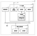
- FIG. 1 shows an example of a configuration of a driving assistance system 10 including a locator device and a processing device according to an embodiment.
- the driving assistance system 10 is mounted on a vehicle 1 and configured to assist a driver in driving the vehicle 1 based on map data in a high-precision map database.
- the driving assistance system 10 includes an imaging device 11, a Global Navigation Satellite System (GNSS) antenna 12, a locator device 20, and a driving assistance device 30.
- the imaging device 11, the locator device, and the driving assistance device 30 are connected to a communication bus BUS.
- GNSS Global Navigation Satellite System
- the imaging device 11 is configured to generate captured images by capturing images of the area in front of the vehicle 1.
- the imaging device 11 may be a monocular camera or a stereo camera.
- the imaging device 11 includes a lens and an image sensor.
- the imaging device 11 is disposed inside the vehicle 1 near the upper part of the windshield of the vehicle 1.
- the imaging device 11 generates a series of captured images by performing imaging operations at a series of imaging timings according to a predetermined frame rate (e.g., 10 fps).
- the imaging device 11 then transmits image data of the generated captured images to the driving assistance device 30 via the communication bus BUS.
- the GNSS antenna 12 is configured to receive signals transmitted from GNSS satellites such as GPS (Global Positioning System).
- GPS Global Positioning System
- the locator device 20 is configured to detect the position of the vehicle 1 in an absolute coordinate system based on the signal received by the GNSS antenna 12, and to generate various data necessary for driving assistance based on the detection results of the position of the vehicle 1.
- the locator device 20 has a GNSS receiving unit 21, a processing unit 22, a storage unit 23, and a communication unit 24.
- the GNSS receiver 21 is configured to detect the position of the vehicle 1 in the absolute coordinate system based on the signal received by the GNSS antenna 12.
- the processing unit 22 is configured, for example, using one or more processors, one or more memories, etc., and is configured to generate driving path data DT and differential position data E.
- the driving path data DT includes data indicating the position of the driving path on which the vehicle 1 may travel.
- the differential position data E includes data indicating the difference in the position and orientation of the vehicle 1 at two different imaging timings.
- the processing unit 22 sets a partial area R based on the vehicle 1 in a direction in which the vehicle 1 may travel. Then, based on the high-precision map database DB stored in the memory unit 23, the processing unit 22 generates driving path data DT including data indicating the position of the driving path in this partial area R.
- This driving path data DT is expressed in a vehicle coordinate system based on the vehicle 1. Note that in addition to data indicating the position of the driving path, the driving path data DT may include various data about the driving path, such as data indicating the position of road signs on the driving path and the contents of the signs.
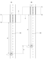
- FIG. 3 shows an example of the partial region R set by the processing unit 22, where (A) shows the position of the partial region R set at a certain imaging timing, and (B) shows the position of the partial region R set at the imaging timing next to that imaging timing.
- the vehicle 1 is traveling on a road 100.
- so-called left-hand traffic where the vehicle travels in the left lane of the road 100, is described, but the present invention is not limited to this, and the vehicle may also travel in the right-hand lane of the road 100, where the vehicle travels in the right lane.
- the processing unit 22 sets a partial region R in front of the vehicle 1, in this example at a position that is a distance d1 away from the imaging device 11 of the vehicle 1.
- the position of the leading end of the partial region R is position T1
- the position of the trailing end of the partial region R is position T2.
- the processing unit 22 generates road data DT including data indicating the position of the road in this partial region R based on the high-precision map database DB stored in the storage unit 23.
- the data indicating the position of the road is data that represents the lane markings of the road 100 as a sequence of points. The position of this sequence of points is expressed in the vehicle coordinate system.
- the locator device 20 transmits this road data DT to the driving assistance device 30 via the communication bus BUS.
- the vehicle 1 has traveled a distance A compared to the imaging timing of FIG. 3(A).
- the processing unit 22 sets a partial area R in front of the vehicle 1 at a position a distance d1 away from the imaging device 11 of the vehicle 1.
- the processing unit 22 then generates driving path data DT including data indicating the position of the driving path in this partial area R based on the high-precision map database DB stored in the memory unit 23.
- the locator device 20 then transmits this driving path data DT to the driving assistance device 30 via the communication bus BUS.
- the position T1 of the leading edge of the partial region R shown in FIG. 3(A) and the position T2 of the trailing edge of the partial region R shown in FIG. 3(B) are almost the same.
- the partial region R in FIG. 3(A) and the partial region R in FIG. 3(B) are not separated from each other and do not overlap each other in the extension direction of the travel path 100.
- the processing unit 22 sets the two partial regions R in this way so that the two partial regions R are not separated from each other and do not overlap each other at two adjacent imaging timings.
- data indicating the position of the travel path can be transmitted from the locator device 20 to the driving assistance device 30 without waste or omission.
- the two partial regions R are separated from each other, part of the data indicating the position of the travel path will be missing. Also, for example, if the two partial regions R overlap each other, the data of the overlapping regions is transmitted and received twice, resulting in waste.
- two partial regions R that are adjacent to each other in the time series are set so that they are close to each other and do not overlap each other, so that data indicating the position of the road can be transmitted and received without waste or omission.
- FIG. 4 shows another example of the partial region R set by the processing unit 22.
- the processing unit 22 reduces the partial region R.
- the processing unit 22 shortens the length of the partial region R in the extension direction of the road 100 (the vertical direction in FIG. 4).
- the distance from the imaging device 11 of the vehicle 1 to the partial region R gradually becomes shorter. If this situation continues for a long time, as shown in FIG. 4, the processing unit 22 sets the partial region R at a position in front of the vehicle 1, a distance d2 away from the imaging device 11 of the vehicle 1, which is shorter than the distance d1.
- the processing unit 22 sets the two partial regions R at two adjacent imaging timings so that they are neither separated from each other nor overlap each other.
- FIG 5 shows another example of partial region R set by processing unit 22.
- congestion occurs in the lane on road 100 in which vehicle 1 is traveling.
- vehicle 1 travels a short distance A in the time between two adjacent image capture timings.
- the position T1 of the leading end of partial region R shown in Figure 5(A) and the position T2 of the rear end of partial region R shown in Figure 5(B) are almost the same.
- processing unit 22 sets two partial regions R so that they are neither separated from each other nor overlap each other in two adjacent image capture timings.
- the processing unit 22 generates differential position data E including data indicating the difference between the position of the vehicle 1 at that imaging timing and the position of the vehicle 1 at the previous imaging timing, and the difference between the orientation of the vehicle 1 at that imaging timing and the orientation of the vehicle 1 at the previous imaging timing.
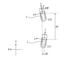
- FIG. 6 shows an example of differential position data E.
- the differential position data E is expressed in an absolute coordinate system based on the high-precision map database DB.
- the absolute coordinate system is a coordinate system using the X direction and the Y direction.
- the vehicle coordinate system is a coordinate system using the x direction and the z direction.
- the differential position data E includes three parameters dX, dY, and d ⁇ .
- the parameter dX is the difference in the position of the vehicle 1 in the X direction at the two image capture timings t11 and t12.
- the parameter dY is the difference in the position of the vehicle 1 in the Y direction at the two image capture timings t11 and t12.
- the parameter ⁇ is the difference in the orientation of the vehicle 1 at the two image capture timings t11 and t12.
- the processing unit 22 sets a partial area R at each imaging timing, and generates roadway data DT including data indicating the position of the road in this partial area R based on the high-precision map database DB.
- the processing unit 22 also generates differential position data E including the three parameters dX, dY, and d ⁇ at each imaging timing.
- the storage unit 23 is configured using a non-volatile storage device such as a semiconductor memory, and is configured to store the high-precision map database DB.
- the communication unit 24 is configured to transmit the driving path data DT and the differential position data E generated by the processing unit 22 to the driving assistance device 30 via the communication bus BUS.
- the driving assistance device 30 is configured to assist the driver in driving the vehicle 1 based on data transmitted from the imaging device 11 and the locator device 20.
- the driving assistance device 30 has a communication unit 31 and a processing unit 32.
- the communication unit 31 is configured to receive image data of the captured image transmitted from the imaging device 11, and the driving path data DT and differential position data E transmitted from the locator device 20.
- the processing unit 32 is configured, for example, using one or more processors, one or more memories, etc., and is configured to perform processing based on the data received by the communication unit 31 and control the operation of the driving assistance system 10.
- the processing unit 32 recognizes a subject based on image data of a captured image transmitted from the imaging device 11, and performs driving assistance based on the recognition result. Specifically, the processing unit 32 can control the operation of the driving assistance system 10 so that the driving assistance system 10 notifies the driver of information about the recognized subject, for example.
- the processing unit 32 also restores the position of the road along which the vehicle 1 may travel, based on the time series data of the road data DT and the time series data of the differential position data E transmitted from the locator device 20. The processing unit 32 then performs driving assistance based on the restored road position. Specifically, the processing unit 32 can control the operation of the driving assistance system 10 so that, when the vehicle 1 is about to deviate from the driving lane, the driving assistance system 10 warns the driver or the driving assistance system 10 performs deviation suppression control.
- the locator device 20 corresponds to a specific example of a "locator device” in an embodiment of the present disclosure.
- the processing unit 22 corresponds to a specific example of a "first processing circuit” in an embodiment of the present disclosure.
- the high-precision map database DB corresponds to a specific example of a "map database” in an embodiment of the present disclosure.
- the road data DT corresponds to a specific example of a "road data” in an embodiment of the present disclosure.
- the differential position data E corresponds to a specific example of a "conversion data" in an embodiment of the present disclosure.
- the communication unit 24 corresponds to a specific example of a "first communication circuit" in an embodiment of the present disclosure.
- the driving assistance device 30 corresponds to a specific example of a "processing device” in an embodiment of the present disclosure.
- the communication unit 31 corresponds to a specific example of a "second communication circuit” in an embodiment of the present disclosure.
- the processing unit 32 corresponds to a specific example of a “second processing circuit” in an embodiment of the present disclosure.
- the driving assistance system 10 corresponds to a specific example of an "in-vehicle system" in an embodiment of the present disclosure.
- the imaging device 11 generates an image by imaging the area in front of the vehicle 1, and transmits the image data of the generated image to the driving assistance device 30 via the communication bus BUS.
- the GNSS antenna 12 receives a signal transmitted from a GNSS satellite such as GPS.
- the locator device 20 detects the position of the vehicle 1 in the absolute coordinate system based on the signal received by the antenna 12, and generates the driving path data DT and the differential position data E based on the detection result of the position of the vehicle 1. Then, the locator device 20 transmits the driving path data DT and the differential position data E to the driving assistance device 30 via the communication bus BUS.
- the driving assistance device 30 supports the driver in driving the vehicle 1 based on the data transmitted from the imaging device 11 and the locator device 20. Specifically, the driving assistance device 30 recognizes the subject based on the image data of the image transmitted from the imaging device 11, and performs driving assistance based on the recognition result. Furthermore, the driving assistance device 30 restores the position of the road along which the vehicle 1 may possibly travel, based on the road data DT and the differential position data E transmitted from the locator device 20. Then, the processing unit 32 performs driving assistance based on the restored road position.
- Processing unit 22 of locator device 20 generates driving path data DT including data indicating the position of a driving path along which vehicle 1 may possibly travel at each of the imaging timings, and differential position data E including data indicating the difference between the position and orientation of vehicle 1 at two different imaging timings. Then, communication unit 24 of locator device 20 transmits this driving path data DT and differential position data E to driving assistance device 30 via communication bus BUS. Driving assistance device 30 restores the position of a driving path along which vehicle 1 may possibly travel, based on the time series data of driving path data DT and the time series data of differential position data E transmitted from locator device 20.
- FIG. 7 shows an example of a process for restoring the position of the road 100 in the processing unit 32 of the driving assistance device 30.
- the processing unit 32 of the driving assistance device 30 places a sequence of points indicating lane markings contained in the driving road data DT on the plane of the absolute coordinate system based on, for example, the driving road data DT and the differential position data E obtained at the imaging timing t1.
- the position data of the sequence of points contained in the driving road data DT is expressed in the vehicle coordinate system. Therefore, the processing unit 32 performs coordinate transformation using the differential position data E to convert the positions of the sequence of points in the vehicle coordinate system into positions in the absolute coordinate system.
- the differential position data E indicates the difference in the position and orientation of the vehicle 1 at two imaging timings. Therefore, the processing unit 32 can accumulate multiple past differential position data E and calculate the difference in the position and orientation of the vehicle 1 between a certain imaging timing that serves as a past reference and the current imaging timing based on this multiple differential position data E.
- the processing unit 32 can convert the position of the sequence of points in the vehicle coordinate system to a position in the absolute coordinate system, for example, by using the position and orientation of the vehicle 1 in the absolute coordinate system at the reference imaging timing as initial values.
- the processing unit 32 of the driving assistance device 30 places a sequence of points indicating lane markings contained in the driving road data DT on the plane of the absolute coordinate system, for example, based on the driving road data DT and differential position data E obtained at imaging timing t2. Also, the processing unit 32 of the driving assistance device 30 places a sequence of points indicating lane markings contained in the driving road data DT on the plane of the absolute coordinate system, for example, based on the driving road data DT and differential position data E obtained at imaging timing t3.
- the processing unit 32 of the driving assistance device 30 restores the position of the road 100 by sequentially arranging the sequence of points indicating the lane markings in the absolute coordinate system based on the time series data of the road data DT and the time series data of the differential position data E. The processing unit 32 then performs driving assistance based on the restored position of the road 100.
- the driving assistance system 10 includes a locator device 20 and a processing device (driving assistance device 30).
- the locator device 20 includes a first processing circuit (processing unit 22) capable of generating driving path data DT including data indicating the position of the driving path in partial area R that is expressed in a vehicle coordinate system based on the vehicle 1 and set in a direction in which the vehicle 1 may travel based on the vehicle 1, based on a map database (high-precision map database DB), and conversion data (differential position data E) for performing coordinate conversion from the vehicle coordinate system to an absolute coordinate system, and a first communication circuit (communication unit 24) capable of transmitting time series data of the driving path data DT and time series data of the conversion data (differential position data E).
- processing unit 22 capable of generating driving path data DT including data indicating the position of the driving path in partial area R that is expressed in a vehicle coordinate system based on the vehicle 1 and set in a direction in which the vehicle 1 may travel based on the vehicle 1, based on a map database
- the processing device (driving assistance device 30) is provided with a second communication circuit (communication unit 31) capable of receiving the time series data of the road data DT and the time series data of the conversion data (differential position data E), and a second processing circuit (processing unit 32) capable of restoring the position of the road in the absolute coordinate system based on the time series data of the road data DT and the time series data of the conversion data (differential position data E).
- a second communication circuit capable of receiving the time series data of the road data DT and the time series data of the conversion data (differential position data E)
- processing unit 32 capable of restoring the position of the road in the absolute coordinate system based on the time series data of the road data DT and the time series data of the conversion data (differential position data E).
- this driving assistance system can only transmit and receive data on the road in a narrow area. That is, since the amount of communication data in the communication bus BUS is limited, it is difficult to transmit and receive data on the road in a wide area. In such a case, the driving assistance system may have difficulty in providing driving assistance when the vehicle 1 is traveling at a high speed, for example, when the vehicle 1 is traveling on a highway. In the driving assistance system 10 according to this embodiment, the position of the road over a wide area can be restored as shown in FIG.
- the driving assistance system 10 can transmit and receive data on the road in a wide area while suppressing the amount of communication data. As a result, the driving assistance system 10 can easily provide driving assistance even when the vehicle 1 is traveling at a high speed, for example.
- the transformation data is expressed in an absolute coordinate system and includes differential position data E that indicates the difference between the position and orientation of the vehicle at two different times.
- the transformation data includes differential position data E, so that only data of the difference between the position and orientation of the vehicle at two different times needs to be transmitted and received, thereby reducing the amount of communication data.
- the first processing circuit is capable of generating time series data of the road data DT by sequentially setting a plurality of partial regions R, and generating time series data of the conversion data (differential position data E).
- the first processing circuit is capable of setting two partial regions R that are adjacent to each other in the time series, among the plurality of partial regions R, so that they are not separated from each other and do not overlap each other. This allows the driving assistance system 10 to transmit and receive data indicating the position of the road without waste or omission. That is, for example, if the two partial regions R are separated from each other, part of the data indicating the position of the road will be missing.
- two partial regions R that are adjacent to each other in the time series are set so that they are not separated from each other and do not overlap each other, so that data indicating the position of the road can be transmitted and received without waste or omission.
- the locator device and the processing device are provided.
- the locator device is provided with a first processing circuit capable of generating road data including data indicating the position of the road in a partial area set in a direction in which the vehicle may travel with respect to the vehicle based on a map database, the road data being expressed in a vehicle coordinate system based on the vehicle and the transformation data for performing coordinate transformation from the vehicle coordinate system to an absolute coordinate system, and a first communication circuit capable of transmitting time series data of the road data and time series data of the transformation data.
- the processing device is provided with a second communication circuit capable of receiving the time series data of the road data and the time series data of the transformation data, and a second processing circuit capable of restoring the position of the road in the absolute coordinate system based on the time series data of the road data and the time series data of the transformation data.
- the transformation data is expressed in an absolute coordinate system and includes differential position data that indicates the difference between the position and orientation of the vehicle at two different times. This makes it possible to reduce the amount of communication data.
- the first processing circuit is capable of generating time series data of road data by sequentially setting a plurality of partial areas, and generating time series data of converted data.
- the first processing circuit is capable of setting two partial areas, among the plurality of partial areas, that are adjacent to each other in the time series so that they are not separated from each other and do not overlap each other. This makes it possible to transmit and receive data indicating the position of the road without waste or omission.
- the coordinate conversion from the vehicle coordinate system to the absolute coordinate system is performed using the differential position data E indicating the difference between the position and orientation of the vehicle at two different timings, but this is not limited to the above.
- the coordinate conversion from the vehicle coordinate system to the absolute coordinate system may be performed using conversion data including data of a conversion matrix that can directly convert the coordinate from the vehicle coordinate system to the absolute coordinate system.
- the positions of the sequence of points included in the road data DT can be converted from the vehicle coordinate system to the absolute coordinate system using one conversion data.
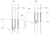
- one piece of road data DT is transmitted and received at each imaging timing, but the present invention is not limited to this. Instead, for example, as shown in FIG. 9, a plurality of road data DT may be transmitted and received.
- an intersection 101 is provided in front of the vehicle 1 on the road 100. The vehicle 1 may proceed straight through the intersection 101, turn left at the intersection 101, or turn right at the intersection 101. Therefore, the processing unit 22 of the locator device 20 sets three partial areas R (partial areas R1 to R3) in three directions in which the vehicle 1 may travel.
- the processing unit 22 generates road data DT including data indicating the positions of the road in these three partial areas R1 to R3 based on the high-precision map database DB stored in the storage unit 23. Then, the communication unit 24 of the locator device 20 transmits the road data DT together with the differential position data E to the driving support device 30 via the communication bus BUS.
- processing unit 22 of locator device 20 may set only partial region R1. That is, in this case, since there is a high possibility that vehicle 1 will turn left at intersection 101, only partial region R1 is set. If the turn signal of vehicle 1 indicates that vehicle 1 will turn left, processing unit 22 may set only partial region R1.
- the processing unit 22 generates the driving road data DT including data indicating the position of the driving road in this partial area R based on the high precision map database DB stored in the storage unit 23, but this is not limited to this.
- the processing unit 22 may communicate with a server in which the high precision map database DB is stored, and generate the driving road data DT including data indicating the position of the driving road in the partial area R based on the high precision map database DB stored in this server.
- the locator device 20 transmits the driving path data DT and the differential position data E at each imaging timing, but this is not limited to this.
- the locator device 20 may transmit the driving path data DT and the differential position data E, for example, once every two imaging timings.
- the locator device 20 may transmit the driving path data DT and the differential position data E periodically, for example, at a timing different from the imaging timings.
- a first processing circuit capable of generating, based on a map database, travel path data including data indicating positions of travel paths in partial areas that are expressed in a vehicle coordinate system based on a vehicle and that are set in directions along which the vehicle may travel based on the vehicle, and conversion data for performing coordinate conversion from the vehicle coordinate system to an absolute coordinate system; a first communication circuit capable of transmitting the time series data of the road data and the time series data of the converted data.
- the transformation data includes differential position data that is expressed in the absolute coordinate system and indicates a difference between a position and an orientation of the vehicle at two different times.
- the first processing circuit is By sequentially setting a plurality of the partial regions, it is possible to generate time series data of the road data and generate time series data of the conversion data,
- the first communication circuit is capable of transmitting time series data of the road data and time series data of the converted data
- the locator device according to any one of (1) to (4), wherein the first processing circuit is capable of changing a size of the partial region based on a progress degree of the vehicle at adjacent timings in time-series data.
- the vehicle may travel in multiple directions;
- the locator device according to any one of (1) to (5), wherein the partial region includes a plurality of partial regions respectively corresponding to the plurality of directions.
- a second communication circuit capable of receiving roadway data, the roadway data being expressed in a vehicle coordinate system based on the vehicle and including data indicating the position of a roadway in a partial area set in a direction along which the vehicle may travel based on the vehicle, and conversion data for performing coordinate conversion from the vehicle coordinate system to an absolute coordinate system; a second processing circuit capable of restoring a position of the road in the absolute coordinate system based on the time series data of the road data and the time series data of the converted data.
- the second processing circuit is capable of performing driving assistance control of the vehicle based on the restored position of the driving path.
- a locator device; A processing device; The locator device comprises: a first processing circuit capable of generating, based on a map database, roadway data including data indicating the position of a roadway in a partial area that is expressed in a vehicle coordinate system based on a vehicle and that is set in a direction in which the vehicle may travel based on the vehicle, and conversion data for performing coordinate conversion from the vehicle coordinate system to an absolute coordinate system; a first communication circuit capable of transmitting the time series data of the road data and the time series data of the converted data; The processing device includes: A second communication circuit capable of receiving the time series data of the road data and the time series data of the converted data; and a second processing circuit capable of restoring a position of the road in the absolute coordinate system based on the time series data of the road data and the time series data of the transformed data.
- the at least one processor may be configured to perform all or a portion of the various functions of the processing unit 22 shown in FIG. 2 by reading instructions from at least one non-transitory and tangible computer-readable medium.
- Such media may take a variety of forms, including, but not limited to, various magnetic media such as hard disks, various optical media such as CDs or DVDs, and various semiconductor memories (i.e., semiconductor circuits) such as volatile or non-volatile memories. Volatile memories may include DRAM and SRAM.
- Non-volatile memories may include ROM and NVRAM.
- An ASIC is an integrated circuit (IC) specialized to perform all or a portion of the various functions of the processing unit 22 shown in FIG. 2.
- An FPGA is an integrated circuit designed to be configurable after manufacture to perform all or a portion of the various functions of the processing unit 22 shown in FIG. 2. The same applies to the processing unit 32 shown in FIG. 2.
Landscapes
- Physics & Mathematics (AREA)
- General Physics & Mathematics (AREA)
- Engineering & Computer Science (AREA)
- Radar, Positioning & Navigation (AREA)
- Remote Sensing (AREA)
- Automation & Control Theory (AREA)
- Traffic Control Systems (AREA)
Abstract
Selon un mode de réalisation de la présente divulgation, un dispositif de localisation comprend : un premier circuit de traitement qui, sur la base d'une base de données de cartes, peut générer des données de trajet de déplacement, qui sont représentées par un système de coordonnées de véhicule concernant un véhicule et comprennent des données indiquant la position d'un trajet de déplacement dans une région partielle définie dans une direction dans laquelle le véhicule pourrait se déplacer en référence au véhicule, et des données de conversion pour effectuer une conversion de coordonnées du système de coordonnées de véhicule à un système de coordonnées absolues ; et un premier circuit de communication qui peut transmettre des données chronologiques concernant les données de trajet de déplacement et des données chronologiques concernant les données de conversion.
Priority Applications (1)
| Application Number | Priority Date | Filing Date | Title |
|---|---|---|---|
| PCT/JP2023/042043 WO2025109727A1 (fr) | 2023-11-22 | 2023-11-22 | Dispositif de localisation, dispositif de traitement et système embarqué |
Applications Claiming Priority (1)
| Application Number | Priority Date | Filing Date | Title |
|---|---|---|---|
| PCT/JP2023/042043 WO2025109727A1 (fr) | 2023-11-22 | 2023-11-22 | Dispositif de localisation, dispositif de traitement et système embarqué |
Publications (1)
| Publication Number | Publication Date |
|---|---|
| WO2025109727A1 true WO2025109727A1 (fr) | 2025-05-30 |
Family
ID=95826164
Family Applications (1)
| Application Number | Title | Priority Date | Filing Date |
|---|---|---|---|
| PCT/JP2023/042043 Pending WO2025109727A1 (fr) | 2023-11-22 | 2023-11-22 | Dispositif de localisation, dispositif de traitement et système embarqué |
Country Status (1)
| Country | Link |
|---|---|
| WO (1) | WO2025109727A1 (fr) |
Citations (2)
| Publication number | Priority date | Publication date | Assignee | Title |
|---|---|---|---|---|
| JP2002197469A (ja) * | 2000-12-26 | 2002-07-12 | Nissan Motor Co Ltd | 車線検出装置 |
| WO2018134863A1 (fr) * | 2017-01-17 | 2018-07-26 | 株式会社日立製作所 | Dispositif de commande de parcours d'un corps mobile |
-
2023
- 2023-11-22 WO PCT/JP2023/042043 patent/WO2025109727A1/fr active Pending
Patent Citations (2)
| Publication number | Priority date | Publication date | Assignee | Title |
|---|---|---|---|---|
| JP2002197469A (ja) * | 2000-12-26 | 2002-07-12 | Nissan Motor Co Ltd | 車線検出装置 |
| WO2018134863A1 (fr) * | 2017-01-17 | 2018-07-26 | 株式会社日立製作所 | Dispositif de commande de parcours d'un corps mobile |
Similar Documents
| Publication | Publication Date | Title |
|---|---|---|
| EP3470789B1 (fr) | Appareil et procédé de support de conduite autonome | |
| US12367687B2 (en) | Vehicular lane keeping system | |
| US11983011B2 (en) | Vehicle driving assist system | |
| US8913786B2 (en) | Driving support system, driving support program, and driving support method | |
| CN115427759A (zh) | 地图信息校正方法、驾驶辅助方法及地图信息校正装置 | |
| US20200302787A1 (en) | Traffic control system for automatic driving vehicle | |
| CN112703540A (zh) | 驾驶辅助方法和驾驶辅助装置 | |
| KR102730150B1 (ko) | 차량의 센서 융합 장치 및 방법 | |
| WO2017104209A1 (fr) | Dispositif d'aide à la conduite | |
| CN116513194A (zh) | 移动体控制装置、移动体控制方法及存储介质 | |
| CN108475468A (zh) | 位置推测装置、位置推测方法及位置推测程序 | |
| US20180158339A1 (en) | Display device for vehicle | |
| EP4416028A1 (fr) | Commande d'activation de fonctionnalité de systèmes d'assistance à la conduite avancée utilisant une carte numérique et une détection embarquée pour confirmer le fonctionnement sûr d'un véhicule | |
| CN110088576A (zh) | 车辆控制系统、车辆控制方法以及车辆控制程序 | |
| US20200284603A1 (en) | Information processing apparatus for vehicle, information processing system for vehicle, and control apparatus for vehicle | |
| WO2025109727A1 (fr) | Dispositif de localisation, dispositif de traitement et système embarqué | |
| JP7167891B2 (ja) | 画像処理装置 | |
| JP7598697B2 (ja) | 撮像情報記憶装置、撮像情報記憶方法及びプログラム | |
| CN114762020A (zh) | 周边车辆位置推定系统、周边车辆位置推定程序 | |
| CN115145260A (zh) | 数据修正装置、数据修正方法、数据修正程序以及车辆 | |
| US20220281459A1 (en) | Autonomous driving collaborative sensing | |
| WO2018089179A1 (fr) | Systèmes, véhicules et procédés pour afficher automatiquement des données d'image lorsqu'un véhicule est situé sur une rampe d'accès à une route | |
| JP5308810B2 (ja) | 車載映像表示装置 | |
| US12552370B2 (en) | Merge assist apparatus | |
| US20260014986A1 (en) | Travel control apparatus, driving training apparatus, and vehicle |
Legal Events
| Date | Code | Title | Description |
|---|---|---|---|
| 121 | Ep: the epo has been informed by wipo that ep was designated in this application |
Ref document number: 23959470 Country of ref document: EP Kind code of ref document: A1 |