WO2025120708A1 - Orifice de charge et procédé de commande - Google Patents
Orifice de charge et procédé de commande Download PDFInfo
- Publication number
- WO2025120708A1 WO2025120708A1 PCT/JP2023/043329 JP2023043329W WO2025120708A1 WO 2025120708 A1 WO2025120708 A1 WO 2025120708A1 JP 2023043329 W JP2023043329 W JP 2023043329W WO 2025120708 A1 WO2025120708 A1 WO 2025120708A1
- Authority
- WO
- WIPO (PCT)
- Prior art keywords
- port
- door
- load port
- substrate
- opening
- Prior art date
- Legal status (The legal status is an assumption and is not a legal conclusion. Google has not performed a legal analysis and makes no representation as to the accuracy of the status listed.)
- Pending
Links
Images




Classifications
-
- H—ELECTRICITY
- H10—SEMICONDUCTOR DEVICES; ELECTRIC SOLID-STATE DEVICES NOT OTHERWISE PROVIDED FOR
- H10P—GENERIC PROCESSES OR APPARATUS FOR THE MANUFACTURE OR TREATMENT OF DEVICES COVERED BY CLASS H10
- H10P72/00—Handling or holding of wafers, substrates or devices during manufacture or treatment thereof
- H10P72/30—Handling or holding of wafers, substrates or devices during manufacture or treatment thereof for conveying, e.g. between different workstations
- H10P72/34—Handling or holding of wafers, substrates or devices during manufacture or treatment thereof for conveying, e.g. between different workstations the wafers being stored in a carrier, involving loading and unloading
- H10P72/3406—Handling or holding of wafers, substrates or devices during manufacture or treatment thereof for conveying, e.g. between different workstations the wafers being stored in a carrier, involving loading and unloading involving removal of lid, door or cover
-
- E—FIXED CONSTRUCTIONS
- E05—LOCKS; KEYS; WINDOW OR DOOR FITTINGS; SAFES
- E05F—DEVICES FOR MOVING WINGS INTO OPEN OR CLOSED POSITION; CHECKS FOR WINGS; WING FITTINGS NOT OTHERWISE PROVIDED FOR, CONCERNED WITH THE FUNCTIONING OF THE WING
- E05F15/00—Power-operated mechanisms for wings
- E05F15/70—Power-operated mechanisms for wings with automatic actuation
- E05F15/73—Power-operated mechanisms for wings with automatic actuation responsive to movement or presence of persons or objects
-
- H—ELECTRICITY
- H10—SEMICONDUCTOR DEVICES; ELECTRIC SOLID-STATE DEVICES NOT OTHERWISE PROVIDED FOR
- H10P—GENERIC PROCESSES OR APPARATUS FOR THE MANUFACTURE OR TREATMENT OF DEVICES COVERED BY CLASS H10
- H10P72/00—Handling or holding of wafers, substrates or devices during manufacture or treatment thereof
- H10P72/06—Apparatus for monitoring, sorting, marking, testing or measuring
- H10P72/0606—Position monitoring, e.g. misposition detection or presence detection
-
- H—ELECTRICITY
- H10—SEMICONDUCTOR DEVICES; ELECTRIC SOLID-STATE DEVICES NOT OTHERWISE PROVIDED FOR
- H10P—GENERIC PROCESSES OR APPARATUS FOR THE MANUFACTURE OR TREATMENT OF DEVICES COVERED BY CLASS H10
- H10P72/00—Handling or holding of wafers, substrates or devices during manufacture or treatment thereof
- H10P72/30—Handling or holding of wafers, substrates or devices during manufacture or treatment thereof for conveying, e.g. between different workstations
-
- H—ELECTRICITY
- H10—SEMICONDUCTOR DEVICES; ELECTRIC SOLID-STATE DEVICES NOT OTHERWISE PROVIDED FOR
- H10P—GENERIC PROCESSES OR APPARATUS FOR THE MANUFACTURE OR TREATMENT OF DEVICES COVERED BY CLASS H10
- H10P72/00—Handling or holding of wafers, substrates or devices during manufacture or treatment thereof
- H10P72/30—Handling or holding of wafers, substrates or devices during manufacture or treatment thereof for conveying, e.g. between different workstations
- H10P72/34—Handling or holding of wafers, substrates or devices during manufacture or treatment thereof for conveying, e.g. between different workstations the wafers being stored in a carrier, involving loading and unloading
- H10P72/3408—Docking arrangements
-
- H—ELECTRICITY
- H10—SEMICONDUCTOR DEVICES; ELECTRIC SOLID-STATE DEVICES NOT OTHERWISE PROVIDED FOR
- H10P—GENERIC PROCESSES OR APPARATUS FOR THE MANUFACTURE OR TREATMENT OF DEVICES COVERED BY CLASS H10
- H10P72/00—Handling or holding of wafers, substrates or devices during manufacture or treatment thereof
- H10P72/30—Handling or holding of wafers, substrates or devices during manufacture or treatment thereof for conveying, e.g. between different workstations
- H10P72/34—Handling or holding of wafers, substrates or devices during manufacture or treatment thereof for conveying, e.g. between different workstations the wafers being stored in a carrier, involving loading and unloading
- H10P72/3411—Handling or holding of wafers, substrates or devices during manufacture or treatment thereof for conveying, e.g. between different workstations the wafers being stored in a carrier, involving loading and unloading involving loading and unloading of wafers
-
- E—FIXED CONSTRUCTIONS
- E05—LOCKS; KEYS; WINDOW OR DOOR FITTINGS; SAFES
- E05Y—INDEXING SCHEME ASSOCIATED WITH SUBCLASSES E05D AND E05F, RELATING TO CONSTRUCTION ELEMENTS, ELECTRIC CONTROL, POWER SUPPLY, POWER SIGNAL OR TRANSMISSION, USER INTERFACES, MOUNTING OR COUPLING, DETAILS, ACCESSORIES, AUXILIARY OPERATIONS NOT OTHERWISE PROVIDED FOR, APPLICATION THEREOF
- E05Y2900/00—Application of doors, windows, wings or fittings thereof
- E05Y2900/10—Application of doors, windows, wings or fittings thereof for buildings or parts thereof
- E05Y2900/11—Application of doors, windows, wings or fittings thereof for buildings or parts thereof for industrial buildings
Definitions
- the present invention relates to a load port and a control method.
- Containers such as FOUPs that house substrates such as semiconductor wafers are known.
- Such containers are opened and closed at a load port provided on a substrate transport device to insert and remove substrates from inside.
- a sensor detects the substrates inside the container to confirm the presence of substrates inside the container (Patent Documents 1 and 2).
- the sensor is sometimes called a mapping sensor.
- the load port of Patent Document 2 is configured such that the door section 22 and mapping sensors m1 and m2 move in the horizontal direction D and the vertical direction H.
- the mapping sensors m1 and m2 are arranged in positions that do not interfere with the frame 21 when the door section 22 is in the fully closed position (C).
- mapping sensors m1 and m2 in Patent Document 2 are disposed so that they protrude further from the door portion in a direction away from the storage container (see Figures 20 and 22).
- the mapping sensors m1 and m2 also move together with the door portion 22. Extra space is required by the amount of the protrusion of the mapping sensors m1 and m2.
- the object of the present invention is to provide a load port that reduces the protrusion of the sensor that detects the substrate when the port door is in the retracted position.
- a load port is provided.
- the present invention provides a load port that reduces the protrusion of the sensor that detects the substrate when the port door is in the retracted position.
- FIG. 2 is an external view of a load port according to an embodiment of the present invention installed in a substrate transport apparatus.
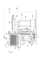
- FIG. 2 is a diagram showing an internal mechanism of the load port and the substrate transport device of FIG. 1 .
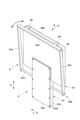
- FIG. FIG. 2 is a perspective view of the port door and mapping unit.
- FIG. 4 is a diagram illustrating the operation of a mapping unit.
- FIG. 2 is an explanatory diagram of the operation of the load port of FIG. 1 .
- FIG. 2 is an explanatory diagram of the operation of the load port of FIG. 1 .
- FIG. 2 is an explanatory diagram of the operation of the load port of FIG. 1 .
- FIG. 2 is an explanatory diagram of the operation of the load port of FIG. 1 .
- 5 is a timing chart showing changes in the position of the port door and the mapping sensor.
- Fig. 1 is an external view of a load port 1 according to an embodiment of the present invention, showing an aspect in which it is installed on a substrate transfer device 100.
- Fig. 2 is a view showing the internal mechanism of the load port 1 and the substrate transfer device 100, and is a schematic cross-sectional view when a container 200 is placed on the load port 1.
- arrows X and Y indicate horizontal directions that are orthogonal to each other, and arrow Z indicates the up and down direction.
- the load port 1 is a device that opens and closes a container 200 such as a FOUP.
- the container 200 has a box-shaped container body 201 with an opening 201a on the side through which a circular substrate W such as a semiconductor wafer is inserted and removed, and a door part 202 that is removably attached to the opening 201a and closes the opening 201a, and stores the substrate W.
- FIG. 2 shows a state in which the door part 202 has been removed from the container body 201 by the load port 1, allowing the substrate transport robot 110 to access the substrate W inside the container 200.
- the load port 1 is attached to a substrate transport device 100 that has a substrate transport robot 110 therein that transports substrates W.
- the substrate transport device 100 has a housing 102 that houses the substrate transport robot 110.
- the load port 1 is attached to the front wall 102a of the housing 102. In the example of FIG. 1, two load ports 1 are attached to the front wall 102a.
- the substrate transport robot 110 transports substrates W in and out of a container 200 placed on the load port 1.
- the substrate transport robot 110 includes an end effector 111 that holds the substrate W, an articulated arm 112 that holds the end effector 111 so that it can at least move forward and backward, and a drive unit 113 that rotates and raises and lowers the articulated arm 112.
- the substrate transport robot 110 further includes a traveling unit 114 that moves the substrate transport robot 110 back and forth in the Y direction. As shown by the dashed line in FIG. 2, the substrate W is loaded and unloaded by inserting the end effector 111 of the substrate transport robot 110 into the interior of a container body 201 having an opening 201a facing the substrate transport device 100.
- the load port 1 includes a mounting table 2 on which a container 200 is placed, a port plate 3, a port door 4, a support 5 that supports the mounting table 2, and a mapping unit 6.
- the port plate 3 is a plate-shaped wall extending in the Z direction, which covers an opening formed in the front wall 102a and, together with the front wall 102a, separates the external space on the mounting table 2 side from the transport space 101 for the substrate W inside the substrate transport device 100.
- the port plate 3 can also be considered a member that constitutes part of the front wall 102a.
- the port plate 3 includes an opening 30 through which the removed door section 202 and end effector 111 can pass in the X direction.
- the mounting table 2 includes a dock plate 20 on which the container 200 is placed.
- the dock plate 20 is provided with a number of positioning pins (kinematic pins) that support the container 200 while positioning it, an occupancy sensor that detects the presence of the container 200, a locking mechanism that locks the container 200 placed on the dock plate 20 to the dock plate 20, and the like.
- the mounting table 2 includes a drive mechanism 21 that displaces the dock plate 20 in the X direction.
- the support section 5 is a hollow body in the shape of a rectangular parallelepiped.
- the support section 5 is provided with a lifting unit 7 that raises and lowers the port door 4 relative to the opening 30, and an advance/retract unit 8 that moves the port door 4 forward and backward in the advance/retract direction (the X direction in this embodiment) relative to the opening 30.
- the port door 4 is supported by the advance/retract unit 8, and the lifting unit 7 raises and lowers the port door 4 by raising and lowering the advance/retract unit 8.
- the lifting unit 7 is a ball screw mechanism. However, it may be another driving mechanism.
- the lifting unit 7 includes a ball screw shaft 71, a slider 72, a motor 73 as a driving source, and a belt transmission mechanism 74.
- the ball screw shaft 71 extends in the Z direction and is supported by the port plate 3 so as to be freely rotatable.
- the ball screw shaft 71 is connected to the belt transmission mechanism 74 at its lower end.
- the slider 72 has an engagement portion that engages with the rail member 32, and can reciprocate in the Z direction by being guided by the rail member 32.
- the rail member 32 extends in the Z direction and is supported by the port plate 3.
- the belt transmission mechanism 74 includes a driven pulley connected to the ball screw shaft 71, a drive pulley connected to the output shaft of the motor 73, and an endless belt wound around these.
- the rotational force of the motor 73 is transmitted to the ball screw shaft 71 via the belt transmission mechanism 74, causing the ball screw shaft 71 to rotate.
- the rotation of the ball screw shaft 71 causes the slider 72 to rise and fall.
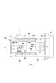
- FIG. 3 is a plan view of the advance/retract unit 8.
- the advance/retract unit 8 is disposed below the mounting table 2, and includes a main frame 80, a linear guide 81, a pair of moving bodies 82, and a drive mechanism 83.
- the main frame 80 includes a pair of side plates 80a spaced apart in the Y direction, an end plate 80b on the port plate 3 side that connects the pair of side plates 80a, and a bottom plate 80c that connects the pair of side plates 80a.
- the end plate 80b is fixed to the slider 72, and the advance/retract unit 8 rises and falls as the slider 72 rises and falls.
- the pair of moving bodies 82 are plate-shaped arm members that extend in the X direction, passing through a pair of slits 31 in the port plate 3.
- the pair of slits 31 extend in the Z direction.
- the support portion 41 of the port door 4 is fixed to the X direction ends of the pair of moving bodies 82.
- Each moving body 82 is supported by the corresponding side plate 80a via a linear guide 81, and is freely displaceable in the X direction.
- the linear guide 81 includes a rail member 81a fixed to the moving body 82, and multiple sliders 81b fixed to the side plate 80a.
- the multiple sliders 81b engage with the rail member 81a that extends in the X direction.
- the rail member 81a is freely reciprocable in the X direction guided by the slider 81b.
- the driving mechanism 83 is provided on the bottom plate 80c, and is a cam mechanism that moves the pair of moving bodies 82 in the X direction.
- the driving mechanism 83 includes a motor 84 as a driving source, a rotating shaft 85, an arm member 86, a roller 87, and a cam member 88.
- the rotating shaft 85 is an axial member extending in the Z direction, and is connected to the output shaft of the motor 84 via a transmission mechanism (e.g., a belt transmission mechanism) not shown, and rotates around the Z axis by the driving force of the motor 84.
- the arm member 86 is fixed to the rotating shaft 85 at one end, and rotates around the rotating shaft 85 as a result of the rotation of the rotating shaft 85.
- a roller 87 that is rotatable around the Z axis is supported on the other end of the arm member 86.
- the cam member 88 is an L-shaped member with one end fixed to one of the pair of moving bodies 82, and a cam hole 89 formed in the other end.
- the cam hole 89 is an oval opening.
- a roller 87 is inserted into the cam hole 89, and the circumferential surface of the roller 87 contacts the inner surface of the cam hole 89.
- the motor 84 By rotating the motor 84, the arm member 86 rotates, and the roller 87 performs a circular motion around the rotation shaft 85.
- the roller 87 abuts against the inner surface of the cam hole 89, the relative position of the roller 87 and the cam hole 89 in the Y direction changes, and the moving body 82 moves in the X direction. This causes the port door 4 to advance and retreat in the X direction.
- FIG. 4 is a perspective view of the port door 4 and the mapping unit 6.
- the port door 4 includes a holding part 40 that holds the door part 202 and a support part 41 that supports the holding part 40.
- the holding part 40 is provided with, for example, a suction mechanism, which allows it to hold the door part 202 by suction.
- the holding part 40 is also provided with an operating mechanism (latch key) that operates the opening and closing of the lock mechanism provided in the door part 202, which allows the container body 201 and the door part 202 to be removed and attached.
- the support part 41 includes a body 41a and a cover member 41b, and is a hollow body that extends in the Z direction.
- the body 41a is a box-shaped member that opens on the side of the substrate transport device 100 (the side opposite the mounting table 2) in the X direction, and the cover member 41b is provided on the body 41a so as to be detachable so as to cover the opening of the body 41a.
- the cover member 41b is fixed to the body 41a by a plurality of bolts.
- the mapping unit 6 is a substrate detection mechanism that is provided on the port door 4 and scans the substrates W in the container body 201 in the Z direction when the port door 4 is lowered.
- the mapping unit 6 includes a pair of mapping sensors 60 that detect the substrates W contained in the container body 201, and a displacement unit 600 that displaces the pair of mapping sensors 60 in the forward and backward direction of the port door 4 (the X direction in this embodiment).
- the pair of mapping sensors 60 are optical sensors, one of which includes a light-emitting element and the other a light-receiving element.
- Optical axis 60a in Figure 4 indicates the optical axis of light traveling from the light-emitting element to the light-receiving element.
- the substrate W blocks the optical axis 60a, causing a change in the detection result of the light-receiving element. This makes it possible to measure the presence or absence and position of the substrate W.
- the displacement unit 600 includes a frame 61 that supports a pair of mapping sensors 60, and a rotation mechanism 63 that is provided on the support portion 41 and rotates the frame 61 in the forward/backward direction of the port door 4 (the X direction in this embodiment).
- the frame 61 has a rectangular shape surrounding the holding portion 40 as a whole, and includes a pair of support columns 61a, a beam portion 61b, and an axis portion 61c.
- the beam portion 61b is a rod-shaped member extending in a horizontal direction (Y direction in this embodiment) intersecting with the forward and backward direction of the port door 4 (X direction in this embodiment).
- the pair of mapping sensors 60 are supported by the beam portion 61b at a distance in the Y direction.
- the axis portion 61c is an axis member extending parallel to the beam portion 61b, and is the rotation center of the rotation of the frame 61 by the rotation mechanism 63.
- the pair of support columns 61a are rod-shaped members that are spaced apart from each other in the extension direction of the beam portion 61b (Y direction in this embodiment), and each extends in the Z direction.
- One end side (upper side) of the pair of support columns 61a is connected to the beam portion 61b, and the other end side (lower side) is connected to the axis portion 61c.
- the rotating mechanism 63 is a mechanism for rotating the frame 61 around the shaft portion 61c, and in this embodiment, is disposed in the internal space of the support portion 41, which is formed by the main body 41a and the cover member 41b. By covering the rotating mechanism 63 with the cover member 41b, it is possible to prevent dust and the like from the rotating mechanism 63 from escaping to the outside.
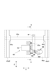
- Figure 5 is a diagram showing the rotating mechanism 63 inside the support portion 41, and is a diagram showing the state with the cover member 41b removed.
- Figure 6 is a cross-sectional view of line A-A in Figure 5.
- the main body 41a of the support portion 41 is provided with a pair of side portions 41a1, 41a2.
- the pair of side portions 41a1, 41a2 are plate-shaped members spaced apart from each other in the horizontal direction (Y direction in this embodiment) and each extending in the Z direction.
- a hole through which the shaft portion 61c is inserted is formed in the pair of side portions 41a1, 41a2, and a bearing portion 41c that supports the shaft portion 61c rotatably around the Y axis is formed in the pair of side portions 41a1, 41a2.
- the shaft portion 61c is supported rotatably around the Y axis by the bearing portion 41c that is integrally formed with the pair of side portions 41a1, 41a2.
- the rotating mechanism 63 includes a motor 64, which is a drive source, a cam member 66, and an arm member 67.
- the rotating mechanism 63 further includes a position detection unit 69.
- the motor 64 is fixed to the main body 41a via a bracket 65.
- the output shaft 64a of the motor 64 extends in the Y direction and rotates around the Y axis.
- the cam member 66 has a cylindrical shape and is an eccentric cam with the output shaft 64a fixed at a position offset from its central axis.
- the cam member 66 rotates when driven by the motor 64.
- the rotating mechanism 63 is supported by the support portion 41 with the motor 64 fixed to the main body 41a via the bracket 65.
- the support portion 41 forms a space in which the rotating mechanism 63 is disposed by the main body 41a, a pair of side portions 41a1 and 41a2, and a cover member 41b.
- the member that rotatably supports the shaft portion 61c is not limited to the bearing portion 41c that is integrally formed with the pair of side portions 41a1, 41a2, but may be provided in the space in which the rotation mechanism 63 is disposed as a separate member from the pair of side portions 41a1, 41a2.
- the arm member 67 has the shaft portion 61c fixed to one end (upper end) and is a member extending in the radial direction of the shaft portion 61c.
- a cam hole 67a is formed in the other end (lower end) of the arm member 67.
- the cam hole 67a is an opening with an oval cross section, and the circumferential surface of the cam member 66 contacts its inner surface.
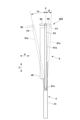
- FIG. 7 is an explanatory diagram.
- position P1 is the position closest to the transfer space 101
- position P3 is the position closest to the external space (position on the container 200 side)
- position P2 is a position between positions P1 and P3.
- Position P2 is the reference position for determining the tilt angles of positions P1 and P3, and the tilt angle of the support pillar 61a in the X direction can be considered to be 0 degrees.
- the support pillar 61a at position P2 is the starting line for determining the tilt angles of positions P1 and P3.
- position P2 is a standby position where the support pillar 61a is in a vertical position facing the Z direction and the tilt angle is 0 degrees.
- the mapping sensor 60 is located above the holding portion 40 of the port door 4.
- Position P3 is a scanning position where the support portion 61a is inclined more toward the external space (toward the container 200) than position P2, with the inclination angle being + ⁇ degrees.
- the inclination angle is positive on the external space side and negative on the transport space 101 side.
- One end (upper end) of the support portion 61a is located on the external space side (the container 200 side), and the mapping sensor 60 is located closer to the external space (the container 200 side) than the holding portion 40 of the port door 4.
- Position P1 is a retracted position where the support pillar 61a is inclined more toward the transport space 101 than position P2, with the inclination angle being - ⁇ degrees.
- One end (upper end) of the support pillar 61a is located on the transport space 101 side, and the mapping sensor 60 is located on the transport space 101 side of the holding portion 40 of the port door 4.
- the position of the frame 61 is detected by the position detection unit 69.
- the position detection unit 69 is built into the support portion 41 together with the rotation mechanism 63.
- the position detection unit 69 includes a plurality of optical sensors 691 to 693 arranged in the X direction.
- the optical sensors 691 to 693 are photointerrupters.
- a detection piece 68 is fixed to the other end (lower end) of the arm member 67.
- the position of the detection piece 68 in the X direction changes in response to the rotation of the arm member 67, that is, the rotation of the frame 61.
- the optical sensors 691 to 693 arranged in the X direction detect the detection piece 68 at different positions in the X direction.
- the position of the frame 61 can be identified from the detection result of the detection piece 68.
- the three positions P1 to P3 of the frame 61 illustrated in FIG. 7 are detected. Therefore, three optical sensors 691 to 693 are provided.
- the configuration of the position detection unit 69 is just one example, and the number, arrangement, and type of sensors can be designed as appropriate.
- the load port 1 is provided with a control unit 10.
- the control unit 10 is an electronic circuit that controls the load port 1.
- the control unit 10 includes, for example, a processing unit represented by a CPU, a storage unit such as a RAM or ROM, an input/output interface between an external device and the processing unit, and a communication interface that communicates with a computer such as a host computer and peripheral devices (such as the substrate transport robot 110) via a communication line.
- the control unit 10 acquires the detection results of various sensors and controls various drive sources.
- the various sensors include, for example, the mapping sensor 60, the optical sensors 691 to 693, the presence sensor of the dock plate 20, the sensor provided in the lift unit 7, the sensor provided in the advance/retract unit 8, and the like.
- the various drive sources include the motor 64, the motor 73, the motor 84, the drive source of the drive mechanism 21, the drive source of the holding unit 40, and the like.
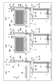
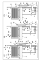
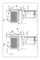
- FIG. 8 to 11 show an example of the operation of the load port 1 under the control of the control unit 10, and in particular show an example of control of the advance/retract operation of the port door 4 and the displacement operation of the mapping sensor 60 in a series of operations from loading the container 200, opening the container 200, detecting the substrate W, and closing the container 200.
- Figure 12 is a timing chart showing the transition of the positions of the port door 4 and the mapping sensor 60 in the series of operations shown in Figures 8 to 11.
- positions P1 to P3 of the mapping sensor 60 are the positions P1 to P3 shown in FIG. 7.
- Positions Pf and Pb of the port door 4 indicate the position of the port door 4 in the X direction, with position Pf being the forward position on the side of the container 200 and position Pb being the backward position on the side of the transport space 101.
- Positions Pu, Ps, Pe, and Pd of the port door 4 indicate the position of the port door 4 in the Z direction.
- Position Pu is the attachment/detachment position where the holding part 40 is at the same height as the container 200 and the opening 30, and is the upper limit position of the port door 4.
- Position Pd is the standby position where the holding part 40 is at a lower position than the container 200 and the opening 30, and is the lower limit position of the port door 4.
- Position Ps is the detection start position where detection of the substrate W by the mapping sensor 60 begins, and is lower than the attachment/detachment position Pu and higher than the standby position Pd.
- Position Pe is the detection end position where detection of the substrate W by the mapping sensor 60 ends, and is lower than the detection start position Ps and higher than the standby position Pd.
- State ST1 shows the stage before the container 200 is loaded onto the mounting table 200.
- the dock plate 20 is in a position away from the port plate 3.
- the port door 4 is in the attachment/detachment position Pu and forward position Pf.
- the opening 30 is closed by the holding portion 40.
- the mapping sensor 60 is in the retracted position P1. In the retracted position P1, the mapping sensor 60 faces the port plate 3 above the opening 30. By positioning the mapping sensor 60 in the retracted position P1, interference between the mapping sensor 60 and the port plate 3 is avoided.
- State ST2 indicates the stage where the container 200 is placed on the dock plate 20 of the mounting table 200.
- the positions of the port door 4 and the mapping sensor 60 are the same as in state ST1.
- State ST3 indicates the stage where the dock plate 20 advances relative to the port plate 3, and the door portion 202 of the container 200 is connected to the holding portion 40 of the port door 4.
- the positions of the port door 4 and the mapping sensor 60 are the same as in state ST1.
- the door portion 202 is held from the side of the transport space 101 by the holding portion 40, and the door portion 202 is unlocked from the container 200.
- State ST4 shows the stage where the door part 202 is separated from the container body 201 of the container 200 and the container 200 is opened.
- the port door 4 is moved backward from the forward position Pf to the backward position Pb by the forward/backward unit 8.
- the mapping sensor 60 is displaced in the opposite direction by the rotation mechanism 63 and moves forward from the backward position P1 to the waiting position P2.
- the port door 4 and the mapping sensor 60 move toward the transport space 101.
- the intrusion amount of the mapping sensor 60 into the transport space 101 is reduced, and the movement space of the substrate transport robot 110 can be secured more widely.
- the mapping sensor 60 and the frame 61 can be suppressed, and the influence of the mapping unit 6 on the transport space 101 can be reduced.
- the amount of operation required to displace the mapping sensor 60 to the scanning position P3, which will be described later is reduced.
- the operation time required to displace the mapping sensor 60 to the scanning position P3 is reduced, and the cycle time required for mapping can be reduced.
- State ST5 indicates the stage where the port door 4 has been lowered by the lifting unit 7 from the attachment/detachment position Pu to the detection start position Ps.
- the mapping sensor 60 is maintained at the standby position P2.
- the position of the mapping sensor 60 is at the height of the opening 30 in the vertical direction (more specifically, below the height of the upper end of the opening 30).
- State ST6 indicates the stage where the mapping sensor 60 has been displaced from the standby position P2 to the scanning position P3 by the rotation mechanism.
- the mapping sensor 60 enters the container 200 (container body 201) from the opening 30.
- the optical axis 60a (FIG. 4) is in a position within the container 200 where it can detect the substrate W contained in the container 200.
- State ST7 shows the stage where the port door 4 is lowered from the detection start position Ps to the detection end position Pe by the lifting unit 7.
- the mapping sensor 60 detects the substrate W from the side of the transport space 101, and the detection result and the detection position are stored in the memory of the control unit 10.
- State ST8 shows the stage where the mapping sensor 60 is displaced from the scanning position P3 to the waiting position P2 by the rotating mechanism 63. By returning the mapping sensor 60 from the scanning position P3 to the waiting position P2, interference between the container body 201 and the edge of the opening 30 and the mapping sensor 60 is avoided.
- State ST9 shows the stage where the port door 4 is lowered from the detection end position Pe to the waiting position Pd by the lifting unit 7. The position of the mapping sensor 60 is the waiting position P2. After this, the substrate W is taken out by the substrate transport robot 110, the substrate W is processed by a processing device (not shown), and the processed substrate W is stored in the container body 201.
- Figure 11 shows the operation of attaching the door part 202 to the container body 201 to close the container 200, and the operation starts when the port door 4 and mapping sensor 60 are in the position ST9 in Figure 10.
- State ST10 shows the stage where the port door 4 is raised from the standby position Pd to the attachment/detachment position Pu by the lifting unit 7. During the rise, the mapping sensor 60 is maintained at the standby position P2.
- State ST11 shows the stage where the door part 202 is attached to the container body 201 of the container 200 to close the container 200.
- the forward/backward unit 8 moves the port door 4 forward from the retreat position Pb to the forward position Pf.
- the rotation mechanism 63 displaces the mapping sensor 60 in the opposite direction and retreats from the standby position P2 to the retreat position P1.
- the port door 4 and the mapping sensor 60 move toward the external space (the container 200 side), but by retreating the mapping sensor 60 from the standby position P2 to the retreat position P1, it is possible to avoid the mapping sensor 60 interfering with the port plate 3 above the opening 30.
- the mapping sensor 60 is displaced in the X direction in the opposite direction to the port door 4, thereby reducing the amount of intrusion of the mapping sensor 60 into the transport space 101 and preventing interference between the mapping sensor 60 and the port plate 3. Therefore, it is possible to provide a load port 1 that has little effect on the transport space 101 of the substrate transport device 100 and has improved protection performance for the mapping sensor 60.
- a displacement unit 600 that displaces the pair of mapping sensors 60 in the forward and backward directions is provided on the support portion 41 that supports the holding portion 40 of the port door 4.
- the size of the load port 1 can be suppressed.
- the displacement unit 600 can be made smaller, and the area occupied by the mapping unit 6 can be saved.
- the lifting unit 7 lifts and lowers the mapping unit 6 together with the port door 4, but by miniaturizing the displacement unit 600 (particularly by suppressing the downward protrusion of the port door 4), the amount of movement of the slider 72 required to open and close the container 200 is reduced. Therefore, the lifting unit 7 can be made smaller.
Landscapes
- Container, Conveyance, Adherence, Positioning, Of Wafer (AREA)
- Sheets, Magazines, And Separation Thereof (AREA)
Abstract
Priority Applications (7)
| Application Number | Priority Date | Filing Date | Title |
|---|---|---|---|
| JP2025516055A JPWO2025120708A1 (fr) | 2023-12-04 | 2023-12-04 | |
| KR1020267000882A KR20260009402A (ko) | 2023-12-04 | 2023-12-04 | 로드 포트 |
| KR1020257007964A KR102912447B1 (ko) | 2023-12-04 | 2023-12-04 | 로드 포트 및 제어 방법 |
| PCT/JP2023/043329 WO2025120708A1 (fr) | 2023-12-04 | 2023-12-04 | Orifice de charge et procédé de commande |
| CN202380065749.1A CN120435762A (zh) | 2023-12-04 | 2023-12-04 | 装载端口以及控制方法 |
| TW113144620A TWI914017B (zh) | 2023-12-04 | 2024-11-20 | 裝載埠及控制方法 |
| US19/083,612 US20250215738A1 (en) | 2023-12-04 | 2025-03-19 | Load port and control method |
Applications Claiming Priority (1)
| Application Number | Priority Date | Filing Date | Title |
|---|---|---|---|
| PCT/JP2023/043329 WO2025120708A1 (fr) | 2023-12-04 | 2023-12-04 | Orifice de charge et procédé de commande |
Related Child Applications (1)
| Application Number | Title | Priority Date | Filing Date |
|---|---|---|---|
| US19/083,612 Continuation US20250215738A1 (en) | 2023-12-04 | 2025-03-19 | Load port and control method |
Publications (1)
| Publication Number | Publication Date |
|---|---|
| WO2025120708A1 true WO2025120708A1 (fr) | 2025-06-12 |
Family
ID=95979685
Family Applications (1)
| Application Number | Title | Priority Date | Filing Date |
|---|---|---|---|
| PCT/JP2023/043329 Pending WO2025120708A1 (fr) | 2023-12-04 | 2023-12-04 | Orifice de charge et procédé de commande |
Country Status (5)
| Country | Link |
|---|---|
| US (1) | US20250215738A1 (fr) |
| JP (1) | JPWO2025120708A1 (fr) |
| KR (2) | KR102912447B1 (fr) |
| CN (1) | CN120435762A (fr) |
| WO (1) | WO2025120708A1 (fr) |
Citations (7)
| Publication number | Priority date | Publication date | Assignee | Title |
|---|---|---|---|---|
| JP2006294642A (ja) * | 2005-04-05 | 2006-10-26 | Yaskawa Electric Corp | ウエハ飛出しセンサ、ロードポートおよびロードポートの制御方法 |
| JP2013069965A (ja) * | 2011-09-26 | 2013-04-18 | Tdk Corp | ロードポート装置及び被処理物の検出方法 |
| JP2014225695A (ja) * | 2005-07-11 | 2014-12-04 | ブルックス オートメーション インコーポレイテッド | 基板ローディングデバイス |
| JP2015050410A (ja) * | 2013-09-04 | 2015-03-16 | ローツェ株式会社 | 複数種類の半導体ウエハを検出するロードポート |
| JP2016164927A (ja) * | 2015-03-06 | 2016-09-08 | シンフォニアテクノロジー株式会社 | ドア開閉装置 |
| JP2019087598A (ja) * | 2017-11-06 | 2019-06-06 | シンフォニアテクノロジー株式会社 | ロードポート、及びロードポートにおけるマッピング処理方法 |
| KR102127008B1 (ko) * | 2019-11-11 | 2020-06-29 | 주식회사 케이씨티 | 로드포트 모듈용 개폐도어 결합형 매핑장치 |
Family Cites Families (4)
| Publication number | Priority date | Publication date | Assignee | Title |
|---|---|---|---|---|
| JP4246420B2 (ja) | 2000-09-14 | 2009-04-02 | 平田機工株式会社 | Foupオープナ及びfoupオープナのマッピング方法 |
| JP3699348B2 (ja) | 2000-11-30 | 2005-09-28 | 平田機工株式会社 | 駆動部隔離foupオープナ |
| WO2004097927A1 (fr) * | 2003-04-28 | 2004-11-11 | Tdk Corporation | Appareil de purge et procede de purge |
| JP5796279B2 (ja) * | 2009-07-10 | 2015-10-21 | シンフォニアテクノロジー株式会社 | ロードポート装置、並びにその蓋体着脱装置及びマッピング装置の各昇降機構の制御方法 |
-
2023
- 2023-12-04 WO PCT/JP2023/043329 patent/WO2025120708A1/fr active Pending
- 2023-12-04 KR KR1020257007964A patent/KR102912447B1/ko active Active
- 2023-12-04 KR KR1020267000882A patent/KR20260009402A/ko active Pending
- 2023-12-04 JP JP2025516055A patent/JPWO2025120708A1/ja active Pending
- 2023-12-04 CN CN202380065749.1A patent/CN120435762A/zh active Pending
-
2025
- 2025-03-19 US US19/083,612 patent/US20250215738A1/en active Pending
Patent Citations (7)
| Publication number | Priority date | Publication date | Assignee | Title |
|---|---|---|---|---|
| JP2006294642A (ja) * | 2005-04-05 | 2006-10-26 | Yaskawa Electric Corp | ウエハ飛出しセンサ、ロードポートおよびロードポートの制御方法 |
| JP2014225695A (ja) * | 2005-07-11 | 2014-12-04 | ブルックス オートメーション インコーポレイテッド | 基板ローディングデバイス |
| JP2013069965A (ja) * | 2011-09-26 | 2013-04-18 | Tdk Corp | ロードポート装置及び被処理物の検出方法 |
| JP2015050410A (ja) * | 2013-09-04 | 2015-03-16 | ローツェ株式会社 | 複数種類の半導体ウエハを検出するロードポート |
| JP2016164927A (ja) * | 2015-03-06 | 2016-09-08 | シンフォニアテクノロジー株式会社 | ドア開閉装置 |
| JP2019087598A (ja) * | 2017-11-06 | 2019-06-06 | シンフォニアテクノロジー株式会社 | ロードポート、及びロードポートにおけるマッピング処理方法 |
| KR102127008B1 (ko) * | 2019-11-11 | 2020-06-29 | 주식회사 케이씨티 | 로드포트 모듈용 개폐도어 결합형 매핑장치 |
Also Published As
| Publication number | Publication date |
|---|---|
| KR20260009402A (ko) | 2026-01-19 |
| TW202528219A (zh) | 2025-07-16 |
| JPWO2025120708A1 (fr) | 2025-06-12 |
| US20250215738A1 (en) | 2025-07-03 |
| CN120435762A (zh) | 2025-08-05 |
| KR20250088481A (ko) | 2025-06-17 |
| KR102912447B1 (ko) | 2026-01-13 |
Similar Documents
| Publication | Publication Date | Title |
|---|---|---|
| KR100403663B1 (ko) | 피처리체 수용 박스의 개폐 덮개의 개폐 장치 및피처리체의 처리 시스템 | |
| KR101408294B1 (ko) | 로드 포트 장치 | |
| JP4246420B2 (ja) | Foupオープナ及びfoupオープナのマッピング方法 | |
| KR20130116021A (ko) | 기판 전달 장치, 기판 전달 방법 및 기억 매체 | |
| JPWO2001006560A1 (ja) | 被処理体収容ボックスの開閉蓋の開閉装置及び被処理体の処理システム | |
| JP3939062B2 (ja) | 基板検出装置 | |
| TWI442493B (zh) | Processing device | |
| WO2025120708A1 (fr) | Orifice de charge et procédé de commande | |
| US6717171B2 (en) | Method and apparatus for accessing microelectronic workpiece containers | |
| JP4285708B2 (ja) | 基板検出装置 | |
| JP2002076097A (ja) | ウェハ転送装置およびウェハアライメント方法 | |
| JP2008108966A (ja) | 検出装置及び検出方法 | |
| JP4501674B2 (ja) | ロードポート装置のマッピング装置 | |
| TWI914017B (zh) | 裝載埠及控制方法 | |
| TW202613014A (zh) | 裝載埠 | |
| WO2020122133A1 (fr) | Dispositif de transport de substrat | |
| WO2019073823A1 (fr) | Dispositif d'ouverture de conteneur | |
| KR102076166B1 (ko) | 정렬부가 포함된 카세트모듈 로드락 장치 | |
| JP2002164417A (ja) | 基板の検出方法およびその装置 | |
| KR20260058155A (ko) | 로드 포트 및 반송 시스템 | |
| JP2026075030A (ja) | ロードポート及び搬送システム | |
| CN121925075A (zh) | 装载端口及搬运系统 | |
| KR200380341Y1 (ko) | 파드 반출기능을 갖는 로드 포트 | |
| JP2003124282A (ja) | 基板搬入出装置 | |
| JP2003347391A (ja) | 基板検出装置 |
Legal Events
| Date | Code | Title | Description |
|---|---|---|---|
| WWE | Wipo information: entry into national phase |
Ref document number: 202380065749.1 Country of ref document: CN |
|
| ENP | Entry into the national phase |
Ref document number: 2025516055 Country of ref document: JP Kind code of ref document: A |
|
| WWE | Wipo information: entry into national phase |
Ref document number: 2025516055 Country of ref document: JP |
|
| WWP | Wipo information: published in national office |
Ref document number: 1020257007964 Country of ref document: KR |
|
| 121 | Ep: the epo has been informed by wipo that ep was designated in this application |
Ref document number: 23960397 Country of ref document: EP Kind code of ref document: A1 |
|
| WWP | Wipo information: published in national office |
Ref document number: 202380065749.1 Country of ref document: CN |
|
| WWD | Wipo information: divisional of initial pct application |
Ref document number: 1020267000882 Country of ref document: KR |
|
| WWP | Wipo information: published in national office |
Ref document number: 1020267000882 Country of ref document: KR |