WO2025134875A1 - Dispositif d'alimentation électrique - Google Patents
Dispositif d'alimentation électrique Download PDFInfo
- Publication number
- WO2025134875A1 WO2025134875A1 PCT/JP2024/043704 JP2024043704W WO2025134875A1 WO 2025134875 A1 WO2025134875 A1 WO 2025134875A1 JP 2024043704 W JP2024043704 W JP 2024043704W WO 2025134875 A1 WO2025134875 A1 WO 2025134875A1
- Authority
- WO
- WIPO (PCT)
- Prior art keywords
- power supply
- supply device
- cooling
- secondary battery
- battery holder
- Prior art date
- Legal status (The legal status is an assumption and is not a legal conclusion. Google has not performed a legal analysis and makes no representation as to the accuracy of the status listed.)
- Pending
Links
Images


Classifications
-
- H—ELECTRICITY
- H01—ELECTRIC ELEMENTS
- H01M—PROCESSES OR MEANS, e.g. BATTERIES, FOR THE DIRECT CONVERSION OF CHEMICAL ENERGY INTO ELECTRICAL ENERGY
- H01M10/00—Secondary cells; Manufacture thereof
- H01M10/60—Heating or cooling; Temperature control
- H01M10/61—Types of temperature control
- H01M10/613—Cooling or keeping cold
-
- H—ELECTRICITY
- H01—ELECTRIC ELEMENTS
- H01M—PROCESSES OR MEANS, e.g. BATTERIES, FOR THE DIRECT CONVERSION OF CHEMICAL ENERGY INTO ELECTRICAL ENERGY
- H01M10/00—Secondary cells; Manufacture thereof
- H01M10/60—Heating or cooling; Temperature control
- H01M10/62—Heating or cooling; Temperature control specially adapted for specific applications
- H01M10/625—Vehicles
-
- H—ELECTRICITY
- H01—ELECTRIC ELEMENTS
- H01M—PROCESSES OR MEANS, e.g. BATTERIES, FOR THE DIRECT CONVERSION OF CHEMICAL ENERGY INTO ELECTRICAL ENERGY
- H01M10/00—Secondary cells; Manufacture thereof
- H01M10/60—Heating or cooling; Temperature control
- H01M10/64—Heating or cooling; Temperature control characterised by the shape of the cells
- H01M10/643—Cylindrical cells
-
- H—ELECTRICITY
- H01—ELECTRIC ELEMENTS
- H01M—PROCESSES OR MEANS, e.g. BATTERIES, FOR THE DIRECT CONVERSION OF CHEMICAL ENERGY INTO ELECTRICAL ENERGY
- H01M10/00—Secondary cells; Manufacture thereof
- H01M10/60—Heating or cooling; Temperature control
- H01M10/65—Means for temperature control structurally associated with the cells
- H01M10/656—Means for temperature control structurally associated with the cells characterised by the type of heat-exchange fluid
- H01M10/6567—Liquids
- H01M10/6568—Liquids characterised by flow circuits, e.g. loops, located externally to the cells or cell casings
-
- H—ELECTRICITY
- H01—ELECTRIC ELEMENTS
- H01M—PROCESSES OR MEANS, e.g. BATTERIES, FOR THE DIRECT CONVERSION OF CHEMICAL ENERGY INTO ELECTRICAL ENERGY
- H01M50/00—Constructional details or processes of manufacture of the non-active parts of electrochemical cells other than fuel cells, e.g. hybrid cells
- H01M50/20—Mountings; Secondary casings or frames; Racks, modules or packs; Suspension devices; Shock absorbers; Transport or carrying devices; Holders
- H01M50/204—Racks, modules or packs for multiple batteries or multiple cells
-
- H—ELECTRICITY
- H01—ELECTRIC ELEMENTS
- H01M—PROCESSES OR MEANS, e.g. BATTERIES, FOR THE DIRECT CONVERSION OF CHEMICAL ENERGY INTO ELECTRICAL ENERGY
- H01M50/00—Constructional details or processes of manufacture of the non-active parts of electrochemical cells other than fuel cells, e.g. hybrid cells
- H01M50/20—Mountings; Secondary casings or frames; Racks, modules or packs; Suspension devices; Shock absorbers; Transport or carrying devices; Holders
- H01M50/204—Racks, modules or packs for multiple batteries or multiple cells
- H01M50/207—Racks, modules or packs for multiple batteries or multiple cells characterised by their shape
- H01M50/213—Racks, modules or packs for multiple batteries or multiple cells characterised by their shape adapted for cells having curved cross-section, e.g. round or elliptic
-
- Y—GENERAL TAGGING OF NEW TECHNOLOGICAL DEVELOPMENTS; GENERAL TAGGING OF CROSS-SECTIONAL TECHNOLOGIES SPANNING OVER SEVERAL SECTIONS OF THE IPC; TECHNICAL SUBJECTS COVERED BY FORMER USPC CROSS-REFERENCE ART COLLECTIONS [XRACs] AND DIGESTS
- Y02—TECHNOLOGIES OR APPLICATIONS FOR MITIGATION OR ADAPTATION AGAINST CLIMATE CHANGE
- Y02E—REDUCTION OF GREENHOUSE GAS [GHG] EMISSIONS, RELATED TO ENERGY GENERATION, TRANSMISSION OR DISTRIBUTION
- Y02E60/00—Enabling technologies; Technologies with a potential or indirect contribution to GHG emissions mitigation
- Y02E60/10—Energy storage using batteries
Definitions
- This disclosure relates to a power supply device.
- Power supply devices are used in which multiple rechargeable secondary battery cells, such as lithium-ion secondary batteries, are connected in series or parallel and housed in an exterior case to drive electrical equipment such as power tools, or to drive electrically-driven mobile objects such as vehicles and construction machinery (see, for example, Patent Document 1).
- the secondary battery cells used in such power supply devices generate heat when charged and discharged, and therefore need to be cooled.
- the amount of heat generated also tends to increase.
- the amount of heat generated by the power system components mounted on the circuit board must also be taken into consideration.
- a cooling pipe 840 for passing a medium such as cooling air may be arranged on the side of a battery block 830 composed of multiple secondary battery cells 801, and heat exchange may be performed by bringing the cooling pipe 840 into contact with the secondary battery cells 801 arranged at the end.
- One of the objectives of one embodiment of the present disclosure is to provide a power supply device that can efficiently cool secondary battery cells.
- Another objective of another embodiment is to provide a power supply device that facilitates heat exchange in cylindrical secondary battery cells.
- a power supply device includes a plurality of secondary battery cells, each having a cylindrical exterior can with each end face of the cylinder serving as a cell end face, a battery holder that houses the plurality of secondary battery cells, an exterior case that houses the battery holder, and a cooling section that is thermally coupled to a side face of the battery holder, the side face of the battery holder being curved to conform to the outer shape of the exterior can, and the cooling section being curved to conform to the shape of the side face of the battery holder.
- the cooling section is positioned to conform to the outer shape of the secondary battery cell located on the side of the battery holder, thereby increasing the contact area and enabling efficient cooling.
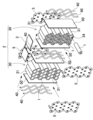
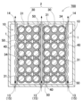
- FIG. 1 is an exploded perspective view showing a power supply device according to a first embodiment.
- FIG. FIG. 2 is an exploded perspective view of the battery module of FIG. 1 .
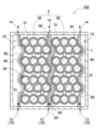
- FIG. 2 is a schematic cross-sectional view of the power supply device of FIG. 1 .
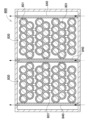
- FIG. 2 is a schematic cross-sectional view showing a power supply device according to a first comparative example.
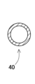
- FIG. 5A is a cross-sectional view of a cooling unit according to the first embodiment.
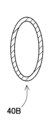
- FIG. 5B is a cross-sectional view of the cooling unit according to the second embodiment.
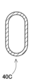
- FIG. 5C is a cross-sectional view of a cooling unit according to the third embodiment.
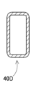
- FIG. 5D is a cross-sectional view of a cooling unit according to the fourth embodiment.
- FIG. 5A is a cross-sectional view of a cooling unit according to the first embodiment.
- FIG. 5B is a cross-sectional view of the cooling unit according to the second embodiment.
- FIG. 5C is
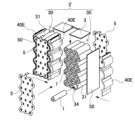
- FIG. 13 is a perspective view showing a battery module of a power supply device according to a fifth embodiment.
- FIG. 13 is a schematic cross-sectional view showing a power supply device according to a sixth embodiment.
- FIG. 11 is a schematic cross-sectional view showing a power supply device according to a second comparative example.
- the multiple secondary battery cells are stacked in multiple tiers in the vertical direction with the end faces of each cell on the same plane, the cell end faces of adjacent secondary battery cells in the vertical direction of the multiple tiers are offset with the center of the circle shifted, the side of the battery holder is formed in a corrugated shape in a cross-sectional view, and the cooling part is formed in a corrugated shape to follow the corrugation of the side of the battery holder.
- the cooling part is formed in a corrugated shape in the same way as the battery holder, which has corrugated sides due to the staggered arrangement, and is in contact with the battery holder over a wide area, thereby improving thermal bonding and improving heat dissipation.
- the cooling section is disposed on each side of the battery holder.
- the cooling section cools both the left and right sides of the battery holder, and the cooling of the internal secondary battery cells is performed from the left and right, thereby promoting heat dissipation.
- the battery holder includes a plurality of battery holders
- the cooling section includes a plurality of cooling sections, each of which is interposed between adjacent battery holders.
- the cooling section is formed in a tubular shape for flowing cooling gas inside.
- the power supply device in any of the above embodiments, further includes a flexible heat-conducting sheet interposed between the battery holder and the cooling section.
- a flexible heat-conducting sheet interposed between the battery holder and the cooling section.
- the power supply device disclosed herein can be used as a power source for portable electrical devices such as power tools and electric cleaners, as a driving power source for mobile objects such as electric carts, electric scooters and assisted bicycles, as a backup power source for servers in stationary power storage applications, as a power supply device for home, business and factory use, and even as a driving power source for vehicles such as hybrid cars and electric automobiles.
- portable electrical devices such as power tools and electric cleaners
- driving power source for mobile objects such as electric carts, electric scooters and assisted bicycles
- servers in stationary power storage applications as a power supply device for home, business and factory use
- a driving power source for vehicles such as hybrid cars and electric automobiles.
- FIG. 1 A power supply device 100 according to a first embodiment of the present disclosure is shown in Figures 1 to 3.
- Figure 1 shows an exploded perspective view of the power supply device 100 according to the first embodiment
- Figure 2 shows an exploded perspective view of the battery module 2 in Figure 1
- Figure 3 shows a schematic cross-sectional view of the power supply device 100 in Figure 1.
- the power supply device 100 shown in these figures includes an exterior case 10, a battery module 2, and a circuit board 3.
- the exterior case 10 houses the battery module 2 and the circuit board 3.
- the exterior case 10 may have any shape that has a storage space inside.
- the exterior case 10 has a box shape with an exterior that extends in one direction.
- the box-shaped exterior case 10 is composed of an upper case 11 and a lower case 12 that are divided into two parts, upper and lower.
- the present disclosure is not limited to this configuration, and the exterior case may be divided into three or more parts.
- the exterior case may also be divided into left and right parts.
- the divided exterior cases are waterproofed by a waterproof structure.
- the exterior case 10 is preferably made of a material with excellent insulating properties, for example a resin such as polycarbonate or PC-ABS alloy. However, the exterior case may also be made of a metal material such as aluminum or its alloy.
- An internal space is provided inside the exterior case 10 to house the battery module 2 and circuit board 3. In the example shown in Figure 1, an internal space is formed in the lower case 12, and the battery module 2 and circuit board 3 are housed therein.
- the exterior case 10 has an external opening 15 in a part thereof.
- the external opening 15 is connected to a cooling air passage.
- the external openings 15 are a first external opening 13 on the bottom surface of the exterior case 10 and a second external opening 14 on the upper side of the exterior case 10.
- the battery module 2 also called a core pack, houses a plurality of secondary battery cells 1.
- the battery module 2 may also be composed of a plurality of battery blocks 30, with each battery block 30 housing a plurality of secondary battery cells 1. In the example of Fig. 2, two battery blocks 30 are stacked laterally to form the battery module 2.
- a circuit board 3 is placed around each battery block 30.
- a cooling unit 40 is arranged on each side of the battery block 30.
- Each battery block 30 includes a battery holder 31, a rechargeable battery cell 1, and a lead plate 5. As shown in Fig. 2, the battery holder 31 has multiple cylindrical holder portions 34 into which a rechargeable battery cell 1 is inserted and held.
- the battery holder 31 may store all the rechargeable battery cells 1 as a whole, or may be divided into multiple sub-holders to store some of the multiple rechargeable battery cells in each sub-holder.
- the battery holder may also be divided in the length direction of the rechargeable battery cells.
- the battery holder 31 is made of a material with excellent insulating properties. It is preferably made of a resin such as polycarbonate or PC-ABS alloy.
- the battery block 30 also includes lead plates 5 for electrically connecting the rechargeable battery cells 1 to each other.
- the lead plates 5 are preferably arranged on the outer surface side of the battery holder 31.
- the lead plates 5 are electrically connected to the terminals of the rechargeable battery cells 1 that are exposed through electrode windows opened in the battery holder 31.
- Each lead plate 5 connects the electrodes of the cell end faces of the secondary battery cells 1 to each other, connecting multiple secondary battery cells 1 together.
- the lead plate 5 is made of a metal plate with excellent conductivity, such as an aluminum plate, a nickel plate, or a copper plate.
- Multiple secondary battery cells 1 are connected in series or in parallel via the lead plate 5.
- the number of series connections and the number of parallel connections can be set as desired according to the required specifications.
- each lead plate 5 mainly connects the end faces of 10 secondary battery cells 1, and a total of 21 secondary battery cells 1 are used in one battery block 30, forming 1 series x 21 parallel.
- two battery blocks 30 are stacked in the longitudinal direction of the secondary battery cells 1, and these battery blocks 30 are connected in series, forming a total of 42 secondary battery cells 1 in 2 series x 21 parallel.
- the number of secondary battery cells and the connection form i.e., the number of series and the number of parallel connections, are not limited to this configuration.
- the battery block 30 is connected to the circuit board 3 via lead plates 5.
- the circuit board 3 is equipped with a charge/discharge circuit that charges and discharges the secondary battery cells 1, and a protection circuit that monitors the voltage and temperature of the secondary battery cells 1 and cuts off the current in the event of an abnormality.
- the circuit board 3 is made of a glass epoxy board or the like.
- a board holder may also be provided as a member for holding the circuit board 3.
- a circuit board 3 is placed on the upper surface of each battery block 30, but the present disclosure is not limited to this configuration, and a single circuit board may be connected to each battery block.
- each battery block 30 houses a secondary battery cell 1 in a battery holder 31.
- Each secondary battery cell 1 may be a secondary battery cell having a cylindrical or rectangular external shape.
- the cylindrical secondary battery cells 1 are used in an outer can arranged in a staggered manner in a horizontal position.
- the number and arrangement of the secondary battery cells 1 are not limited to this example, and any number and arrangement may be appropriately adopted.
- cylindrical secondary battery cells may be arranged in a matrix (details will be described later).
- the secondary battery cells 1 may be any known secondary battery, such as a lithium ion secondary battery, a nickel metal hydride battery, or a nickel cadmium battery.
- Each secondary battery cell 1 has a positive electrode and a negative electrode.
- the positive or negative electrode terminal is preferably provided on one cell end face of the secondary battery cell 1.
- a positive electrode terminal is provided on one cell end face of the secondary battery cell 1, and the other face of the outer can serves as the negative electrode.
- the battery holder 31 stacks multiple secondary battery cells 1 in multiple vertical stages with the end faces of each cell on the same plane. Furthermore, the cell end faces of adjacent secondary battery cells 1 in the multiple stages are offset in the vertical direction with the centers of the circles shifted. As a result, the collection of multiple secondary battery cells 1 stored in the battery block 30 is aligned flat on the top and bottom surfaces, but has an uneven shape on the side surfaces with the centers of the cell end faces shifted. For this reason, the side surfaces of the battery holder 31 are curved to follow the external shape of the exterior can of the secondary battery cells 1, as shown in Figure 3.
- a cooling unit 40 is disposed on the side of the battery holder 31.
- the cooling unit 40 is thermally coupled to the cooling unit 40 via a thermally conductive sheet 50.
- the cooling unit 40 is curved to fit the shape of the side of the battery holder 31. By arranging the cooling unit 40 in this way to fit the outer shape of the secondary battery cells 1 located on the side of the battery holder 31, the contact area is increased, making it possible to perform cooling more efficiently.
- the secondary battery cells stored inside generate heat when they are charged and discharged, and therefore need to be cooled.
- One possible cooling structure is to arrange cooling pipes 840 for flowing a refrigerant such as cooling air on the side of a battery block 30 composed of multiple secondary battery cells 801, as in the power supply device 800 according to the comparative example shown in Figure 4, and to bring the cooling pipes 840 into contact with the secondary battery cells 801 arranged at the ends to exchange heat.
- the secondary battery cells 801 are often stacked vertically in a staggered arrangement with each row offset, as shown in FIG. 4, for space efficiency reasons.
- the secondary battery cells 801 located at the ends of the battery block 830 alternate between being in contact with the cooling pipes 840 installed on the sides of the battery block 830 and not being in contact with them.
- the contact points are line contact and the contact area is small. This makes it difficult to carry out efficient heat exchange.
- the cooling section 40 is not straight, but curved to follow the side shape of the battery holder 31, thereby increasing the contact area, promoting heat exchange, and enabling efficient cooling.
- the side of the battery holder 31 is formed in a corrugated shape in a cross-sectional view.
- the side surfaces of the multiple battery holders 31 constituting each of the two battery blocks 30 face each other so that the corrugated projections and recesses of the adjacent battery holders 31 fit together.
- the cooling section 40 is disposed on the outer side surface and adjacent side surface of each of the two battery blocks 30, and is formed in a corrugated shape so as to follow the corrugation of the side surface of the battery holder 31.
- the cooling section 40 disposed between two adjacent battery blocks 30 is shared by the two battery blocks 30. This ensures the density of the multiple secondary battery cells 1, and the cooling section 40 is formed in a similar corrugated shape to the battery holder 31, whose sides are corrugated due to the staggered arrangement, and the cooling section 40 is brought into contact over a wide area, improving thermal coupling and improving heat dissipation.
- the contact area is made larger, allowing for more efficient air cooling.
- the cooling section 40 can also cool not only the heat generated by the secondary battery cells 1 housed in the battery holder 31, but also the heat generating components mounted on the circuit board 3 placed on the battery holder 31, such as power semiconductors.
- the cooling section 40 is connected to the external opening 15 formed in the exterior case 10. Specifically, as shown in FIG. 3, the first external opening 13, which opens on the bottom surface of the exterior case 10 as the external opening 15, is connected to the lower end of the cooling section 40, and the second external opening 14, which opens on the upper side of the exterior case 10, is connected to the upper end of the cooling section 40.
- the air taken into the exterior case 10 through the external opening 15 is used as a cooling medium and is air-cooled by heat exchange in the cooling section 40.
- a fan or the like may be provided to forcibly flow the cooling air. Note that in this disclosure, an example is described in which cooling air is taken in from the first external opening 13 and discharged from the second external opening 14 as shown in FIG. 3, but this configuration is not limited to this, and it goes without saying that the cooling air may be taken in from the second external opening and discharged from the first external opening.
- the cooling unit 40 may be placed on only one side of the battery holder 31, but preferably, as shown in FIG. 3 etc., multiple cooling units 40 are used and placed on both sides of the battery holder 31. This allows the cooling units 40 to cool both the left and right sides of the battery holder 31, and the cooling of the internal secondary battery cells 1 from both the left and right promotes heat dissipation.
- the battery module 2 includes multiple battery holders 31.
- the cooling sections 40 are not only on the sides of the battery module 2 but also in between the multiple secondary battery cells 1, the secondary battery cells 1 that are located in the middle and prone to trapping heat can be directly cooled by the additional cooling section 40, making it possible to achieve even more efficient cooling.
- the cooling section 40 is made of a metal with excellent electrical conductivity.
- the cooling section 40 is formed into a hollow tube. By flowing a refrigerant such as a cooling gas inside this tube, heat exchange can be achieved with an air-cooled cooling pipe.
- a refrigerant such as a cooling gas inside this tube.
- multiple cooling pipes are arranged at a distance from each other on the side surface of each battery holder 31.
- Each cooling pipe is deformed into a corrugated shape to fit the curved surface of the battery holder 31. This type of configuration can be achieved relatively easily.
- the cross-sectional shape of the cooling pipe can be other than circular as shown in FIG. 5A.
- the cooling section 40B of the power supply device according to embodiment 2 shown in FIG. 5B is a flat pipe with an elliptical cross-sectional shape. This allows the contact area with the battery holder 31 to be increased compared to a circular shape.
- the cross-sectional shape of the cooling section 40C is a track shape. This allows the contact area with the battery holder 31 to be further increased.
- the cross-sectional shape of the cooling section 40D may be rectangular as in the power supply device according to embodiment 4 shown in FIG. 5D. This allows the contact area with the battery holder 31 to be further increased.
- the rectangular cooling section has a rectangular shape with the contact surface with the cooling pipe as the long side. It is also preferable to chamfer the corners.
- the cross-sectional shape is not limited to a square shape, and can also be a polygonal shape such as a triangle.
- thermally conductive sheet 50 with excellent thermal conductivity can be interposed between the battery holder 31 and the cooling unit 40.
- the thermally conductive sheet 50 is flexible. By interposing the flexible thermally conductive sheet 50 between the side surface of the battery holder 31 and the cooling unit 40 in this manner, the gap at the bonding interface between them is reduced, preventing the formation of an insulating layer of air and improving thermal bonding.
- the thermally conductive sheet 50 can be, for example, a 1 mm to 3 mm elastically deformable cushion sheet with excellent thermal conductivity.
- the thermally conductive sheet 50 is sandwiched between the battery holder 31 and the cooling unit 40 in a crushed state and is in close contact with the battery holder 31 and the cooling unit 40. This reduces the formation of a heat insulating layer due to the occurrence of gaps, and brings the battery holder 31 and the cooling unit 40 into close thermal contact, allowing the secondary battery cells 1 to dissipate heat efficiently.
- the thermally conductive sheet 50 is in the form of a sheet that covers the entire side surface of the battery holder 31, but this is not limited to the configuration, and it may be configured to cover only the area where the cooling section contacts the battery holder.
- the thermally conductive sheet may be formed in the form of multiple strips.
- the power supply device 100 is configured to cool each battery block 30 from both sides by the cooling air flowing through the cooling unit 40 inside the exterior case 10.
- the inlets and outlets of the cooling air flowing through the cooling unit 40 are joined to the first external opening 13 opened on the bottom surface of the exterior case 10 and the second external opening 14 opened on the top surface of the exterior case 10.
- the gap between the first external opening 13 and the inlet and outlet of the cooling unit 40, and the gap between the second external opening 14 and the inlet and outlet of the cooling unit 40 are each liquid-tightly sealed by a sealant, and the joint surface between the upper case 11 and the lower case 12 constituting the exterior case 10 is also liquid-tightly sealed by a sealant, so that the exterior case 10 is configured to have a waterproof structure. Therefore, it is possible to prevent water from entering each battery block 30 of the exterior case 10 through the openings of the first external opening 13 and the second external opening 14 provided in the exterior case 10, or the gaps in the joint surface between the upper case 11 and the lower case 12.
- a tubular cooling pipe is used as the cooling unit 40, but the present disclosure does not limit the cooling unit 40 to a tubular shape, and the cooling unit 40 may be plate-shaped.
- the cooling unit 40 may be configured to flow cooling air inside a hollow plate.
- FIG. 6 Such an example is shown in the perspective view of FIG. 6 as a power supply device according to embodiment 5, and its battery module 2'.
- the same components as those in embodiment 1 and the like are given the same reference numerals, and detailed descriptions are omitted as appropriate.
- the cooling section 40E arranged on the side of the battery module 2' shown in Figure 6 is formed in the shape of a hollow corrugated plate.
- the plate is made of a highly conductive material such as metal, and is open at the top and bottom. With this type of cooling section 40E, a single member can cool the entire side of the battery holder 31 over a wide area.
- the power supply device is attached to the electrical device to be driven and supplies power to the electrical device.
- the power supply device can be replaced to continue using the electrical device.
- the present invention is not limited to power supply devices of a replaceable type that mainly houses secondary battery cells, but can also be applied to configurations in which secondary battery cells are housed within the housing of electrical device.
- a power supply device is sufficient as long as it houses secondary battery cells in a case, and also includes power supply devices that have secondary battery cells built in for driving the electrical device itself within the housing.
- the present invention is not limited to replaceable power supply devices, but can also be applied to electrical devices that have built-in secondary battery cells.
- the power supply device can be suitably used as a power source for driving assisted bicycles, self-propelled robots for home delivery, electric carts for home delivery and golf courses, electric scooters, construction machinery, hybrid cars, electric cars, and other vehicles. It can also be used as a power source for portable electrical devices such as walkie-talkies, electric cleaners, and power tools. It can also be used as a cooling mechanism for electrical devices with built-in heating elements, and is not limited to being a power source. It can also be used as a stationary power storage device, for example, a power supply device for home, business, or factory use, or as a backup power source for servers, etc.
Landscapes
- Chemical & Material Sciences (AREA)
- Chemical Kinetics & Catalysis (AREA)
- Electrochemistry (AREA)
- General Chemical & Material Sciences (AREA)
- Engineering & Computer Science (AREA)
- Manufacturing & Machinery (AREA)
- Secondary Cells (AREA)
- Battery Mounting, Suspending (AREA)
Abstract
L'invention concerne un dispositif d'alimentation électrique comprenant : une pluralité d'éléments de batterie secondaires ayant chacun un boîtier extérieur cylindrique, chaque surface d'extrémité du cylindre servant de surface d'extrémité d'élément ; un support de batterie logeant la pluralité d'éléments de batterie secondaire ; un boîtier extérieur logeant le support de batterie ; et une partie de refroidissement couplée thermiquement à une surface latérale du support de batterie. La surface latérale du support de batterie est incurvée le long de la forme externe du boîtier extérieur, et la partie de refroidissement est incurvée le long de la forme de la surface latérale du support de batterie. En plaçant ainsi la partie de refroidissement de façon à suivre la forme extérieure des éléments de batterie secondaires positionnés sur la surface latérale du support de batterie, le refroidissement peut être effectué efficacement en raison d'une augmentation de la zone de contact.
Applications Claiming Priority (2)
| Application Number | Priority Date | Filing Date | Title |
|---|---|---|---|
| JP2023-217216 | 2023-12-22 | ||
| JP2023217216 | 2023-12-22 |
Publications (1)
| Publication Number | Publication Date |
|---|---|
| WO2025134875A1 true WO2025134875A1 (fr) | 2025-06-26 |
Family
ID=96136922
Family Applications (1)
| Application Number | Title | Priority Date | Filing Date |
|---|---|---|---|
| PCT/JP2024/043704 Pending WO2025134875A1 (fr) | 2023-12-22 | 2024-12-10 | Dispositif d'alimentation électrique |
Country Status (1)
| Country | Link |
|---|---|
| WO (1) | WO2025134875A1 (fr) |
Citations (3)
| Publication number | Priority date | Publication date | Assignee | Title |
|---|---|---|---|---|
| WO2012101954A1 (fr) * | 2011-01-28 | 2012-08-02 | 株式会社ニフコ | Bloc-batterie |
| WO2017175487A1 (fr) * | 2016-04-05 | 2017-10-12 | ソニー株式会社 | Bloc-batterie et dispositif électronique le comportant |
| JP2023537450A (ja) * | 2021-07-22 | 2023-09-01 | 寧徳時代新能源科技股▲分▼有限公司 | 熱管理部材、電池及び電気利用装置 |
-
2024
- 2024-12-10 WO PCT/JP2024/043704 patent/WO2025134875A1/fr active Pending
Patent Citations (3)
| Publication number | Priority date | Publication date | Assignee | Title |
|---|---|---|---|---|
| WO2012101954A1 (fr) * | 2011-01-28 | 2012-08-02 | 株式会社ニフコ | Bloc-batterie |
| WO2017175487A1 (fr) * | 2016-04-05 | 2017-10-12 | ソニー株式会社 | Bloc-batterie et dispositif électronique le comportant |
| JP2023537450A (ja) * | 2021-07-22 | 2023-09-01 | 寧徳時代新能源科技股▲分▼有限公司 | 熱管理部材、電池及び電気利用装置 |
Similar Documents
| Publication | Publication Date | Title |
|---|---|---|
| KR101447057B1 (ko) | 전지셀의 장착 및 방열을 위한 방열 지지부재를 포함하는 전지모듈 | |
| JP5540070B2 (ja) | 電池モジュール及び電池パック | |
| JP5779793B2 (ja) | 優れた放熱能力を有するバッテリーモジュール及びそれを使用するバッテリーパック | |
| CN104285315B (zh) | 具有高效冷却结构的电池模块 | |
| KR101326086B1 (ko) | 콤팩트한 구조와 우수한 방열 특성의 전지모듈 및 그것을 포함하는 중대형 전지팩 | |
| KR101218751B1 (ko) | 냉각 효율성이 향상된 중대형 전지팩 | |
| CN102484300B (zh) | 其上安装有温度传感器的电池模块和包括该电池模块的中大型电池组 | |
| EP2432045B1 (fr) | Cartouche de pile comprenant un élément de pression élastique, et module de pile la comprenant | |
| KR101205180B1 (ko) | 콤팩트하고 안정성이 우수한 냉각부재와 이를 포함하는 전지모듈 | |
| CN102473978B (zh) | 具有改善的冷却效率的电池模块 | |
| CN104412439B (zh) | 具有间接空气冷却结构的电池模块 | |
| US11289746B2 (en) | Cooling arrangement for an energy storage device | |
| JP7853276B2 (ja) | 電源装置 | |
| CN107068921A (zh) | 中大型电池组 | |
| KR20100041452A (ko) | 냉각 효율성이 향상된 전지모듈 어셈블리 | |
| JP7666850B2 (ja) | 絶縁油を含む電池モジュール及びこれを含む電池パック | |
| KR101658517B1 (ko) | 냉각 부재를 활용한 전지모듈 | |
| KR101533992B1 (ko) | 전지모듈 | |
| CN114503338A (zh) | 电池模块及包括该电池模块的电池组 | |
| CN121964765A (zh) | 电池组和包括所述电池组的装置 | |
| WO2025134875A1 (fr) | Dispositif d'alimentation électrique | |
| CN116848707A (zh) | 电池组及包括该电池组的装置 | |
| WO2025134768A1 (fr) | Dispositif d'alimentation électrique et procédé de fabrication associé | |
| WO2026014089A1 (fr) | Dispositif d'alimentation électrique | |
| WO2025248893A1 (fr) | Dispositif d'alimentation électrique |
Legal Events
| Date | Code | Title | Description |
|---|---|---|---|
| 121 | Ep: the epo has been informed by wipo that ep was designated in this application |
Ref document number: 24907260 Country of ref document: EP Kind code of ref document: A1 |