WO2025141702A1 - Dispositif d'affichage - Google Patents
Dispositif d'affichage Download PDFInfo
- Publication number
- WO2025141702A1 WO2025141702A1 PCT/JP2023/046688 JP2023046688W WO2025141702A1 WO 2025141702 A1 WO2025141702 A1 WO 2025141702A1 JP 2023046688 W JP2023046688 W JP 2023046688W WO 2025141702 A1 WO2025141702 A1 WO 2025141702A1
- Authority
- WO
- WIPO (PCT)
- Prior art keywords
- color
- drawn
- current
- pointer
- reference scale
- Prior art date
- Legal status (The legal status is an assumption and is not a legal conclusion. Google has not performed a legal analysis and makes no representation as to the accuracy of the status listed.)
- Pending
Links
Images


Classifications
-
- B—PERFORMING OPERATIONS; TRANSPORTING
- B60—VEHICLES IN GENERAL
- B60K—ARRANGEMENT OR MOUNTING OF PROPULSION UNITS OR OF TRANSMISSIONS IN VEHICLES; ARRANGEMENT OR MOUNTING OF PLURAL DIVERSE PRIME-MOVERS IN VEHICLES; AUXILIARY DRIVES FOR VEHICLES; INSTRUMENTATION OR DASHBOARDS FOR VEHICLES; ARRANGEMENTS IN CONNECTION WITH COOLING, AIR INTAKE, GAS EXHAUST OR FUEL SUPPLY OF PROPULSION UNITS IN VEHICLES
- B60K35/00—Instruments specially adapted for vehicles; Arrangement of instruments in or on vehicles
- B60K35/20—Output arrangements, i.e. from vehicle to user, associated with vehicle functions or specially adapted therefor
- B60K35/21—Output arrangements, i.e. from vehicle to user, associated with vehicle functions or specially adapted therefor using visual output, e.g. blinking lights or matrix displays
-
- B—PERFORMING OPERATIONS; TRANSPORTING
- B60—VEHICLES IN GENERAL
- B60K—ARRANGEMENT OR MOUNTING OF PROPULSION UNITS OR OF TRANSMISSIONS IN VEHICLES; ARRANGEMENT OR MOUNTING OF PLURAL DIVERSE PRIME-MOVERS IN VEHICLES; AUXILIARY DRIVES FOR VEHICLES; INSTRUMENTATION OR DASHBOARDS FOR VEHICLES; ARRANGEMENTS IN CONNECTION WITH COOLING, AIR INTAKE, GAS EXHAUST OR FUEL SUPPLY OF PROPULSION UNITS IN VEHICLES
- B60K35/00—Instruments specially adapted for vehicles; Arrangement of instruments in or on vehicles
- B60K35/80—Arrangements for controlling instruments
-
- G—PHYSICS
- G01—MEASURING; TESTING
- G01D—MEASURING NOT SPECIALLY ADAPTED FOR A SPECIFIC VARIABLE; ARRANGEMENTS FOR MEASURING TWO OR MORE VARIABLES NOT COVERED IN A SINGLE OTHER SUBCLASS; TARIFF METERING APPARATUS; MEASURING OR TESTING NOT OTHERWISE PROVIDED FOR
- G01D7/00—Indicating measured values
Definitions
- This case concerns a display device that displays information on variables that reflect the state of a vehicle.
- a meter device that imagines a virtual solid object that can rotate around a specified rotation axis, and draws a projection of the solid object so that the angle of rotation changes according to the power output and vehicle speed.
- a display format that uses such a projection is suitable for presenting various information in a compact manner compared to existing analog meters (see Patent Document 1).
- reference numbers are printed to make it easier to read the size of the rotation angle.
- the image of this reference number is mapped onto the surface of the solid object as a planar texture. Therefore, if the surface on which the reference numbers are attached is significantly inclined with respect to the projection surface, the shape of the reference numbers projected onto the projection surface will be distorted, and good visibility will not be obtained. For example, in the case of the horizontally oriented cylindrical meter described in Patent Document 1, it is difficult to correctly read the reference numbers displayed near the top and bottom ends of the cylindrical surface.
- One of the objectives of this case was devised in light of the above-mentioned problems, and is to provide a display device with improved visibility. However, this objective is not the only objective. Another objective of this case is to achieve effects that cannot be obtained with conventional technology, which are derived from the configurations shown in the "Mode for carrying out the invention" described below.
- the disclosed display device can be realized as the aspects (application examples) disclosed below, which solve at least part of the above problems.
- Each of the aspects from aspect 2 onwards is an aspect that can be selected additionally as appropriate, and each of the aspects can be omitted. None of the aspects from aspect 2 onwards discloses an essential aspect or configuration for the present case.
- the disclosed display device is a display device that displays a projection of a solid object that rotates according to the value of a variable related to a vehicle state, and includes a reference scale and a reference number.
- the reference scale is a mark drawn on the peripheral surface surrounding the rotation axis of the solid object as an indication of the magnitude of the rotation angle relative to a predetermined origin.
- the reference number is disposed in a position adjacent to the reference scale on the projection, represents the value of the variable corresponding to the reference scale, and is drawn to follow the reference scale while maintaining a posture facing directly toward the projection surface of the projection.
- the peripheral surface has a visible surface that is displayed on the projection surface and a non-visible surface that is not displayed on the projection surface. It is also preferable that, as the solid body rotates, when the reference scale moves from the non-visible surface to the visible surface, the reference numbers corresponding to the reference scale are drawn to appear, and when the reference scale moves from the visible surface to the non-visible surface, the reference numbers corresponding to the reference scale are drawn to disappear.
- aspects including aspect 1 above it is preferable that the color of the reference number corresponding to the reference scale is set according to the position of the reference scale on the peripheral surface.
- Aspect 5 In regard to the aspects including Aspect 4 described above, it is preferable that the reference numerals are drawn in a character color of a second color different from the first color, and that the characters are surrounded by an outline of a third color different from the second color.
- Aspect 6 In relation to the aspects including Aspect 4 above, it is preferable to have a first pointer that is drawn in a shape extending from the current point toward the vicinity of the rotation axis.
- Aspect 9 In relation to aspects including aspect 8 above, it is preferable to have a first pointer drawn in a shape extending linearly from the current point toward the rotation axis, and a current value display unit that is disposed adjacent to the end of the first pointer on the opposite side from the current point and displays the current value of the variable in numbers. It is also preferable that the current value display unit is displayed with priority over the second pointer on the projection surface.
- the disclosed display device renders the reference numbers so that they follow the reference scale while maintaining a posture facing the projection surface of the projection drawing. This improves the visibility of the reference numbers regardless of the position of the reference scale. This makes it easier for the user to correctly read the rotation angle, for example, improving the user experience.
- the display device 1 of this embodiment includes an electronic control device 2 and a display 3 (output device).
- the electronic control device 2 is a computer for controlling the content displayed on the display 3, and has a built-in processor (arithmetic processing device) and memory (storage device).
- the processing content (program) of the electronic control device 2 is stored in the memory, and is executed by loading the content into the processor as appropriate.
- the electronic control device 2 may be formed integrally with the display 3 (built into the display 3), or may be provided separately from the display 3.
- Display 3 is a device that outputs information about the vehicle, such as a liquid crystal display device, an organic EL (Electro-Luminescence) display device, or a projector device.
- the information output to display 3 is controlled by electronic control unit 2.
- the shape of the information display area on display 3 is not particularly limited. Display 3 is placed in a position that is easy for the driver to see, such as in front of the driver (in front of the steering wheel) or in the front center of the vehicle interior (in front of the driver's seat and halfway between the passenger seat).
- Display 3 can display, for example, an output meter (tachometer), speedometer, water temperature gauge, oil temperature gauge, motor thermometer, battery thermometer, auxiliary equipment information, road surface information, surrounding radar detection information, various warning icons, etc.
- a touch panel device that detects touch operations on the screen, an input device provided with a keyboard, physical buttons, or a touchpad, a gaze detection device that detects the gaze, a gesture reading device that detects gesture operations, a speaker device, etc. may also be provided.
- variable information displayed on the display 3 may be parameter information that reflects at least the state of the vehicle, and there is no particular limit to the type.
- specific examples of variable information include vehicle speed information, information about the output (power) of the vehicle's drive source, information indicating the vehicle's running state, information indicating the conditions around the vehicle, information indicating the operating state of on-board devices, and detection information from various sensors mounted on the vehicle.
- Specific examples of information related to the output (power) of the vehicle's drive source include engine rotation speed (rpm), engine torque, engine horsepower (power), traction motor rotation speed (rpm), traction motor torque, traction motor horsepower (power), power consumption of the traction motor, power supply from the drive battery, and the output ratio of multiple traction motors (output ratio between front and rear wheels, output ratio between left and right wheels).
- information that indicates the vehicle's driving condition include the shift position, gear ratio of the transmission, driving distance, estimated driving distance, fuel economy, electricity consumption, remaining battery capacity, yaw rate, roll rate, pitch rate, longitudinal acceleration, lateral acceleration, road surface inclination angle, tire pressure, powertrain energy flow, driving direction (azimuth), altitude, temperature, and road surface friction coefficient.
- Other specific examples include the vehicle's current location information, map information, video footage captured by an onboard camera, Internet information, audio information, and multimedia information.
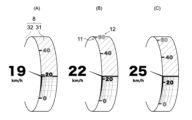
- the cylindrical projection located at the left end is a power meter 4 (image of a power meter) that shows the current drive source output of the vehicle.
- the cylindrical projection located at the right end of each of FIGS. 2(A) and (B) is a speedometer 5 (image of a speedometer) that shows the current vehicle speed.
- An information display area 6 is provided between the power meter 4 and the speedometer 5.
- the information display area 6 can display information that shows the running state of the vehicle, information that shows the situation around the vehicle, information that shows the operating state of the on-board devices, information detected by various sensors mounted on the vehicle, etc.
- the size and color of the power meter 4, the speedometer 5, and the information display area 6 can be changed by the user of the vehicle. Note that the dashed lines in the figures that show the information display area 6 are shown for convenience and do not actually need to be displayed.
- FIG. 4 is a projection diagram showing the configuration of a cylinder 7 that is the prototype of the images of the power meter 4 and the speedometer 5.
- the cylinder 7 is a solid body that rotates around a rotation axis C according to the values of variables related to the vehicle state.
- the cylinder 7 has a peripheral surface 8 that surrounds the rotation axis C, and two top surfaces 9 that intersect with the rotation axis C.
- the peripheral surface 8 has a visible surface 31 that is displayed in the projection diagram, and a non-visible surface 32 that is not displayed in the projection diagram. For one cylinder 7, only one of the top surfaces 9 and the visible surface 31 are depicted in the projection diagram.
- the rotation axis C is set, for example, to extend horizontally (left and right direction of the display screen) in the projection diagram.
- the cylinder 7 shown in FIG. 5 has a number line 30, a current point 34, a center point 35, a current line 36, and an origin line 37.
- the number line 30 corresponds to the intersection of the peripheral surface 8 with a plane that is perpendicular to the axis of rotation C and passes through a predetermined origin 33.
- the reference scale 11 is positioned based on the number line 30, and is drawn so as to be tangent to one side of the number line 30 (the right side of the number line 30 in FIG. 5), for example.
- the current point 34 is a point on the number line 30 that corresponds to the current value of the vehicle speed.
- the movement of the reference numbers 12 relative to the reference scale 11 drawn on the circumferential surface 8 of the rotating cylinder 7 can be understood in analogy with the movement of a gondola (passenger passenger compartment, cabin) rotatably supported on the rim (annular frame) of a rotating Ferris wheel.
- the gondolas of a Ferris wheel always move in a position where the floor is horizontal, regardless of the rotation angle of the rim.
- the reference numbers 12 move to follow the reference scale 11, always in a position that appears to be drawn on a plane parallel to the projection surface, regardless of the rotation angle of the cylinder 7.
- the first pointer 21 is an indicator drawn in a shape extending from the current point 34 toward the vicinity of the rotation axis C.
- the first pointer 21 is drawn, for example, in a wedge shape with one end on the current point 34 side being thick and the other end being thin.
- the other end of the first pointer 21 is preferably disposed near the center point 35 of the top surface 9, and more preferably coincides with the center point 35.
- the first pointer 21 plays a role in making it easier for the user to focus the line of sight on the current point 34. For example, when the user directs his or her line of sight toward the vicinity of the top surface 9 of the cylinder 7, the end portion on the current point 34 side is more likely to be noticed.
- the position of the first pointer 21 in this embodiment is always fixed with respect to the projection surface, but it may be drawn to move according to the rotation speed or angular velocity of the circumferential surface 8.
- the first pointer 21 pivoted to the center point 35 may be drawn to swing according to the rotation speed or angular velocity of the circumferential surface 8.
- the second pointer 22 is an indicator needle that is drawn in the shape of an arc extending from the current point 34 to the origin 33 along the number line 30.
- the second pointer 22 is drawn, for example, in a wedge shape with one end on the current point 34 side being thick and the other end on the origin 33 side being thin.
- the length of the second pointer 22 expands and contracts according to the rotation angle of the cylinder 7, and the larger the current value of the variable (vehicle speed), the longer it is drawn.
- the second pointer 22 plays a role in making it easier for the user to focus their gaze on the current point 34. For example, when the user moves their gaze along the number line 30, the end on the current point 34 side is more likely to be noticed.
- the region of the visible surface 31 other than the first band 24 becomes the second band 25.
- the first belt portion 24 is shaded and the second belt portion 25 is shown with lattice lines. Also, by changing the density of the lattice lines of the second belt portion 25, a color gradation, which will be described later, is expressed.
- Lightness refers to the degree of brightness of a color (the degree to which white is mixed in the achromatic components). The higher the lightness, the more whitish the color, and the lower the lightness, the more blackish the color. It is preferable that the first color contains a lot of achromatic components, and it is preferable that the lightness and saturation are set low, for example.
- the first color (the color of the first band portion 24) is a dark gray color close to black, and the background of the cylinder 7 is a color close to the first color (e.g., black).
- the second band portion 25 is preferably drawn in a color different from the first color, and is preferably set to a color that clearly defines the boundary with the first band portion 24.
- the second band portion 25 is preferably set to a higher brightness and saturation than the first color at the boundary with the first band portion 24.
- the second band portion 25 in this embodiment is drawn with a gradation so that the color difference with the first color increases as it approaches the current point 34. Gradation means that the color changes continuously and stepwise in response to a change in position.
- Color difference is a value that quantifies the perceived color gap between two colors, and is calculated, for example, based on the measurement method of JIS Z 8729-1980 (CIE L*a*b* color system ⁇ 1976>).
- a color can be defined as the coordinates of a point in a multidimensional space (color space). For example, when colors are expressed using HSV (hue, saturation, brightness) or RGB (red, green, blue), the color space becomes three-dimensional, and a color corresponds to the coordinates of a point with three parameters. Therefore, color difference can be quantitatively calculated as the Euclidean distance between two points in a three-dimensional space.
- FIG. 7 is a virtual planar development of second band 25.
- the shape of the developed second band 25 is a rectangle whose width and height are determined by current line 36 and number line 30.
- the point diagonally opposite current point 34 is defined as diagonal point 38
- the right end point of current line 36 (the end point that is not current point 34) is defined as second current point 39.
- the side connecting diagonal point 38 and second current point 39 (the side opposite number line 30) is defined as opposite line 40.
- the color difference from the first color increases as one approaches the number line 30, and the color difference from the first color decreases as one approaches the counter line 40.
- the color near the current point 34 is off-white, and the color near the second current point 39 is gray. If the color difference is large above and below the current line 36, the boundary with the first band 24 becomes clear, making it easier to grasp the current point 34. Therefore, it is preferable that a certain degree of color difference from the first color is maintained not only near the current point 34 but also near the second current point 39. In other words, it is preferable that the color near the second current point 39 is a color different from the first color.
- the color near the current point 34 is off-white
- the color near the origin 33 is gray
- the diagonal point 38 is the same color as the first color (a dark gray that is close to black).
- the entire primitive line 37 may be the same color as the first color. Setting a gradation like this highlights the contrast between the first band 24 and the second band 25, and the user's gaze is more likely to be drawn to the area around the current point 34 where the color difference is greater.
- the first pointer 21, second pointer 22, and third pointer 23 are drawn on a layer higher than the projection of the cylinder 7, the first band portion 24, and the second band portion 25.
- the color of these pointers 21 to 23 is preferably a second color different from the first color.
- the second color (the color of the pointers 21 to 23) is white. This allows the boundary between the first band portion 24 and the second band portion 25 and the positions of the reference scale 11 indicated by the pointers 21 to 23 to be clearly displayed.
- the colors of the first pointer 21, the second pointer 22, and the third pointer 23 may be a gradation color so that the color difference from the first color increases as the pointer approaches the current point 34.
- a gradation may be set so that the color is the second color (white) near the current point 34, and the color becomes closer to the first color (dark gray or black) as the pointer moves away from the current point 34.
- Such a gradation may be set for any of the first pointer 21, the second pointer 22, and the third pointer 23, or for all of the pointers 21 to 23.
- the current value display section 26 and the current status display section 27 are drawn on a layer higher than the projection of the cylinder 7 and the pointers 21 to 23.
- the current value display section 26 and the current status display section 27 are displayed with priority over the second pointer 22 on the projection surface.
- the color of the current value display section 26 and the current status display section 27 is preferably the same color as the first pointer 21, which is the second color. This clearly shows the relationship between the contents of the current value display section 26 and the current status display section 27 and the position of the reference scale 11 pointed to by the first pointer 21.
- the origin 33 is located below the bottom edge of the current value display section 26, so the entire second pointer 22 is drawn.
- the origin 33 is located above the bottom edge of the current value display section 26, so the second pointer 22 is drawn as if it were discontinued at the bottom edge of the current value display section 26. If the origin 33 is located above the top edge of the current value display section 26, then only the portion of the second pointer 22 that is covered by the current value display section 26 may be omitted, or the entire portion above the bottom edge of the current value display section 26 may be omitted.
- the reference scale 11 is drawn on the same layer as the projection of the cylinder 7. Therefore, when the reference scale 11 overlaps with the pointers 21 to 23, the reference scale 11 will be hidden by the pointers 21 to 23. In contrast, the reference numbers 12 are drawn on the top layer, which is higher than all other elements. In this way, even if the reference numbers 12 overlap with the pointers 21 to 23, the reference numbers 12 are always visible.
- the color of the reference scale 11 is preferably a color different from the first color, and more preferably a second color (white).
- the color of the reference numbers 12 is preferably a color different from the first color, and more preferably a second color (white).
- the color of the reference numerals 12 is preferably set according to the position on the circumferential surface 8 of the reference scale 11 adjacent to that reference numeral 12. For example, the closer the position of the reference scale 11 is to the upper or lower end of the circumferential surface 8, the more preferably the reference numerals 12 are drawn in a color with a smaller color difference from the first color. Alternatively, the closer the position of the reference scale 11 is to the boundary between the visible surface 31 and the non-visible surface 32, the more preferably the reference numerals 12 corresponding to that reference scale 11 are drawn lighter. The closer the position of the reference scale 11 is to the vertical center on the circumferential surface 8, the more preferably the color of the reference numerals 12 is set to a color with a larger color difference from the first color.
- an outline or outline color may be applied around the reference numerals 12.
- the character color of the reference numerals 12 may be a second color (white), and an outline of a third color different from the second color may be drawn around the characters.
- the third color is black. This improves the visibility of the reference numerals 12 superimposed on the first band portion 24 and the second band portion 25. In addition, the numerals become easier to read even when the reference numerals 12 overlap the third pointer 23.
- the display device 1 displays a projection of a cylinder 7 (a solid object) that rotates according to the value of a variable related to a vehicle state, and includes a reference scale 11 and reference numerals 12.
- the reference scale 11 is a mark drawn on a peripheral surface 8 surrounding a rotation axis C of the cylinder 7 as an indicator of the magnitude of a rotation angle relative to a predetermined origin 33.
- the reference numerals 12 are arranged at a position adjacent to the reference scale 11 on the projection, and are numerals that represent the value of the variable corresponding to the reference scale 11 and are drawn to follow the reference scale 11 while maintaining a posture facing directly toward the projection surface of the projection.
- the above configuration improves the visibility of the reference numbers 12 regardless of the position of the reference scale 11. This makes it easier for the user to correctly read the rotation angle of the cylinder 7, for example, and makes it possible to accurately communicate the values of variables related to the vehicle state, such as vehicle speed and drive source output. This not only improves the visibility of the display device 1, but also improves ease of use and usability, improving the user experience.
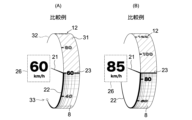
- Figures 9(A) and (B) are comparative examples in which the reference numerals 12 of the speedometer 5 shown in Figures 8(A) and (B) are mapped onto the peripheral surface 8 as a planar texture.
- the shape of the reference numerals 12 will be distorted near the top and bottom ends of the peripheral surface 8, making it difficult to read the reference numerals 12 correctly.
- the shape of the reference numerals 12 will not be distorted even near the top and bottom ends of the peripheral surface 8, improving the visibility of the reference numerals 12.
- the peripheral surface 8 has a visible surface 31 that is displayed on the projection surface and a non-visible surface 32 that is not displayed on the projection surface.
- the reference scale 11 moves from the non-visible surface 32 to the visible surface 31 as the cylinder 7 rotates, the reference numbers 12 corresponding to the reference scale 11 are drawn to appear.
- the reference scale 11 moves from the visible surface 31 to the non-visible surface 32, the reference numbers 12 corresponding to the reference scale 11 are drawn to disappear.
- the reference numerals 12 By drawing the reference numerals 12 in this way, it is possible to display only the reference numerals 12 that are close to the current variable value, making it easier to grasp the current variable value. Also, by making the reference numerals 12 appear and disappear while moving along the peripheral surface 8, the movement of the reference numerals 12 can be made to feel like a series of smooth, flowing movements, creating a sophisticated impression. This can therefore improve the user experience.
- the color of the reference numerals 12 corresponding to the reference scale 11 is set according to the position of the reference scale 11 on the peripheral surface 8. For example, as shown in Figs. 3(A), (B) and 5, the closer the position of the reference scale 11 is to the upper end or lower end of the peripheral surface 8, the smaller the color difference between the reference numerals 12 is drawn in a color.
- This color setting makes the reference numerals 12 easier to see clearly as they move from the back to the front of the peripheral surface 8, improving the visibility of the reference numerals 12.
- the solid object related to the projection is a cylinder 7.
- This cylinder 7 has a number line 30, a current point 34, and a current line 36.
- the number line 30 corresponds to the intersection of the peripheral surface 8 with a plane that is perpendicular to the rotation axis C and passes through the origin 33.
- the current point 34 is a point on the number line 30 that corresponds to the current value of the variable.
- the current line 36 corresponds to the intersection of the plane that passes through the current point 34 and the rotation axis C with the peripheral surface 8.
- the peripheral surface 8 has a first band 24 and a second band 25.
- the first band 24 is an area on one circumferential side of the current line 36, and is drawn in a first color (e.g., dark gray).
- the second band 25 is an area on the other circumferential side of the current line 36, and is drawn with a gradation (e.g., dark gray to grayish white) so that the color difference from the first color increases as the current point 34 is approached.
- a gradation e.g., dark gray to grayish white
- the display device 1 described above includes a first pointer 21 that is drawn in a shape extending from the current point 34 toward the vicinity of the rotation axis C. This allows the user's line of sight to be guided to the current point 34, making it easier to grasp the current value of the variable. Furthermore, by positioning the end of the first pointer 21 opposite the current point 34 near the rotation axis C, it is possible to simulate a state in which the first pointer 21 is journaled on the rotation axis C, thereby enhancing the reality (sense of reality) of the first pointer 21 that is positioned outside the rotating cylinder 7. This allows for an improved user experience.
- the display device 1 is provided with a current value display unit 26 that is disposed adjacent to the end of the first pointer 21 opposite the current point 34 and that displays the current value of the variable in numbers. This allows the user to recognize the current value of the variable indicated by the first pointer 21 in numbers, and information can be conveyed accurately. This improves convenience.
- the display device 1 is provided with a second pointer 22 that is drawn in an arc shape extending from the current point 34 to the origin 33 along the number line 30. This allows the user's gaze to be naturally guided to the current point 34, making it easier to grasp the current value of the variable. Furthermore, the shape of the second pointer 22 that follows the number line 30 can enhance the reality of the second pointer 22 that is positioned on the outside of the rotating cylinder 7. This can improve the user experience.
- the display device 1 described above includes a first pointer 21 and a current value display unit 26.
- the first pointer 21 is drawn in a shape extending in a straight line from the current point 34 toward the rotation axis C.
- the current value display unit 26 is disposed adjacent to the end of the first pointer 21 opposite the current point 34, and displays the current value of the variable in numbers.
- the current value display unit 26 is displayed with priority over the second pointer 22 on the projection surface. This makes it easier to read the numbers on the current value display unit 26.
- the display device 1 has a third pointer 23 that is drawn in a straight line from the current point 34 along the current line 36. This makes it possible to clearly indicate the boundary between the first band 24 and the second band 25, and to clearly show the position of the current point 34. This makes it easier to grasp the current values of variables, improving the user experience.
- the above-mentioned display device 1 is applicable to gasoline vehicles, hybrid vehicles, and plug-in hybrid vehicles (PHEVs) that can be externally charged or powered.
- a plug-in hybrid vehicle is a hybrid vehicle (hybrid electric vehicle, HEV) that is equipped with an engine and motor as a drive source, a generator as a power generation device, and a battery as a power storage device, and that allows the battery to be externally charged or powered from the battery.
- HEV hybrid electric vehicle
- the former type of plug-in hybrid vehicle is equipped with a charging port (inlet) for inserting a charging cable that supplies power from an external charging facility, a non-contact power receiving device, etc.
- the latter type of plug-in hybrid vehicle is equipped with an outlet for external power supply, a non-contact power supply device, etc. It is also possible to install the above-mentioned charging ports and outlets in the same plug-in hybrid vehicle.
Landscapes
- Engineering & Computer Science (AREA)
- Chemical & Material Sciences (AREA)
- Combustion & Propulsion (AREA)
- Transportation (AREA)
- Mechanical Engineering (AREA)
- Physics & Mathematics (AREA)
- General Physics & Mathematics (AREA)
- Instrument Panels (AREA)
Abstract
Un dispositif d'affichage selon la présente divulgation affiche un diagramme de projection d'un solide (7) qui tourne en fonction d'une valeur d'une variable liée à un état de véhicule, le dispositif d'affichage comprenant une échelle de référence (11) et une valeur numérique de référence (12). L'échelle de référence (11) est une marque dessinée sous la forme d'un indice de la taille de l'angle de rotation par rapport à une origine prescrite, sur une surface circonférentielle (8) entourant l'axe de rotation (C) du solide (7). La valeur numérique de référence (12) est un nombre qui est dessiné de façon à être disposé à une position adjacente à l'échelle de référence (11) dans le diagramme de projection, pour représenter une valeur d'une variable correspondant à l'échelle de référence (11) et pour suivre l'échelle de référence (11) dans un état dans lequel une posture faisant face à la surface de projection du diagramme de projection est maintenue.
Priority Applications (2)
| Application Number | Priority Date | Filing Date | Title |
|---|---|---|---|
| PCT/JP2023/046688 WO2025141702A1 (fr) | 2023-12-26 | 2023-12-26 | Dispositif d'affichage |
| JP2025565785A JPWO2025141702A1 (fr) | 2023-12-26 | 2023-12-26 |
Applications Claiming Priority (1)
| Application Number | Priority Date | Filing Date | Title |
|---|---|---|---|
| PCT/JP2023/046688 WO2025141702A1 (fr) | 2023-12-26 | 2023-12-26 | Dispositif d'affichage |
Publications (1)
| Publication Number | Publication Date |
|---|---|
| WO2025141702A1 true WO2025141702A1 (fr) | 2025-07-03 |
Family
ID=96217412
Family Applications (1)
| Application Number | Title | Priority Date | Filing Date |
|---|---|---|---|
| PCT/JP2023/046688 Pending WO2025141702A1 (fr) | 2023-12-26 | 2023-12-26 | Dispositif d'affichage |
Country Status (2)
| Country | Link |
|---|---|
| JP (1) | JPWO2025141702A1 (fr) |
| WO (1) | WO2025141702A1 (fr) |
Citations (7)
| Publication number | Priority date | Publication date | Assignee | Title |
|---|---|---|---|---|
| US20030164756A1 (en) * | 2002-03-01 | 2003-09-04 | Toshiaki Hayashi | Multiple RPM indicating tachometer for motor vehicles |
| JP2008241472A (ja) * | 2007-03-27 | 2008-10-09 | Denso Corp | 表示装置 |
| WO2011158545A1 (fr) * | 2010-06-16 | 2011-12-22 | 矢崎総業株式会社 | Dispositif de mesure graphique |
| JP2013147200A (ja) * | 2012-01-23 | 2013-08-01 | Calsonic Kansei Corp | 車両用表示装置 |
| WO2015190062A1 (fr) * | 2014-06-13 | 2015-12-17 | 株式会社デンソー | Système d'affichage de véhicule |
| JP2019174802A (ja) * | 2018-03-28 | 2019-10-10 | 株式会社リコー | 制御装置、表示装置、表示システム、移動体、制御方法、及びプログラム |
| US11370301B2 (en) * | 2019-06-06 | 2022-06-28 | Volkswagen Aktiengesellschaft | Motion and acceleration sensory speedometer for a transportation vehicle |
-
2023
- 2023-12-26 WO PCT/JP2023/046688 patent/WO2025141702A1/fr active Pending
- 2023-12-26 JP JP2025565785A patent/JPWO2025141702A1/ja active Pending
Patent Citations (7)
| Publication number | Priority date | Publication date | Assignee | Title |
|---|---|---|---|---|
| US20030164756A1 (en) * | 2002-03-01 | 2003-09-04 | Toshiaki Hayashi | Multiple RPM indicating tachometer for motor vehicles |
| JP2008241472A (ja) * | 2007-03-27 | 2008-10-09 | Denso Corp | 表示装置 |
| WO2011158545A1 (fr) * | 2010-06-16 | 2011-12-22 | 矢崎総業株式会社 | Dispositif de mesure graphique |
| JP2013147200A (ja) * | 2012-01-23 | 2013-08-01 | Calsonic Kansei Corp | 車両用表示装置 |
| WO2015190062A1 (fr) * | 2014-06-13 | 2015-12-17 | 株式会社デンソー | Système d'affichage de véhicule |
| JP2019174802A (ja) * | 2018-03-28 | 2019-10-10 | 株式会社リコー | 制御装置、表示装置、表示システム、移動体、制御方法、及びプログラム |
| US11370301B2 (en) * | 2019-06-06 | 2022-06-28 | Volkswagen Aktiengesellschaft | Motion and acceleration sensory speedometer for a transportation vehicle |
Also Published As
| Publication number | Publication date |
|---|---|
| JPWO2025141702A1 (fr) | 2025-07-03 |
Similar Documents
| Publication | Publication Date | Title |
|---|---|---|
| JP5323132B2 (ja) | 車両用計器 | |
| JP5850673B2 (ja) | 自動車用コンビネーションインストルメントおよび自動車 | |
| EP2298587B1 (fr) | dispositif d'affichage, vehicule, méthode d'affichage, programme d'affichage, médium d'enregistrement | |
| CN113263912B (zh) | 车辆用显示装置 | |
| US20150371408A1 (en) | Vehicle Informatin Display System and Methods | |
| JP6337855B2 (ja) | 車両の表示装置 | |
| JP5387978B2 (ja) | 車両用表示装置 | |
| US11813940B2 (en) | Display device | |
| JP5218925B2 (ja) | 車両用メータユニット | |
| JP2019043369A (ja) | 車両用表示装置 | |
| JP2008241471A (ja) | 表示装置 | |
| CN110914094B (zh) | 车辆用显示装置以及显示控制装置 | |
| JP2010277015A (ja) | 車両用表示装置 | |
| WO2019017198A1 (fr) | Dispositif d'affichage pour véhicule et dispositif de commande d'affichage | |
| WO2025141702A1 (fr) | Dispositif d'affichage | |
| JP2008254703A (ja) | 車両用メーターユニット | |
| JP2012088062A (ja) | 車両用表示装置 | |
| JP7709104B1 (ja) | 表示装置 | |
| US5943037A (en) | Viewer orientation indicator for an illustration | |
| JP2009101861A (ja) | 車両用表示装置 | |
| JP7758222B2 (ja) | 表示装置 | |
| JP6968590B2 (ja) | 車両用表示装置 | |
| JP7639937B2 (ja) | 表示装置 | |
| CN120129618A (zh) | 显示装置 | |
| JP2005308489A (ja) | 車両用計器 |
Legal Events
| Date | Code | Title | Description |
|---|---|---|---|
| ENP | Entry into the national phase |
Ref document number: 2025565785 Country of ref document: JP Kind code of ref document: A |
|
| 121 | Ep: the epo has been informed by wipo that ep was designated in this application |
Ref document number: 23963056 Country of ref document: EP Kind code of ref document: A1 |