WO2025142702A1 - Dispositif de support de travail, machine de travail et procédé de support de travail - Google Patents
Dispositif de support de travail, machine de travail et procédé de support de travail Download PDFInfo
- Publication number
- WO2025142702A1 WO2025142702A1 PCT/JP2024/044897 JP2024044897W WO2025142702A1 WO 2025142702 A1 WO2025142702 A1 WO 2025142702A1 JP 2024044897 W JP2024044897 W JP 2024044897W WO 2025142702 A1 WO2025142702 A1 WO 2025142702A1
- Authority
- WO
- WIPO (PCT)
- Prior art keywords
- work
- working
- route
- work machine
- control device
- Prior art date
- Legal status (The legal status is an assumption and is not a legal conclusion. Google has not performed a legal analysis and makes no representation as to the accuracy of the status listed.)
- Pending
Links
Images


Classifications
-
- A—HUMAN NECESSITIES
- A01—AGRICULTURE; FORESTRY; ANIMAL HUSBANDRY; HUNTING; TRAPPING; FISHING
- A01B—SOIL WORKING IN AGRICULTURE OR FORESTRY; PARTS, DETAILS, OR ACCESSORIES OF AGRICULTURAL MACHINES OR IMPLEMENTS, IN GENERAL
- A01B69/00—Steering of agricultural machines or implements; Guiding agricultural machines or implements on a desired track
-
- G—PHYSICS
- G05—CONTROLLING; REGULATING
- G05D—SYSTEMS FOR CONTROLLING OR REGULATING NON-ELECTRIC VARIABLES
- G05D1/00—Control of position, course, altitude or attitude of land, water, air or space vehicles, e.g. using automatic pilots
- G05D1/60—Intended control result
- G05D1/648—Performing a task within a working area or space, e.g. cleaning
Definitions
- the work support device may include a storage device that stores a second driving route that is defined separately from the first driving route and is used by the work machine to automatically travel through the field, and the first control device may define the first driving route by correcting the second driving route based on a deviation of the vehicle body position from the second driving route when the work machine moves to the reference position.
- the first control device may define the first travel route to include a plurality of paths each extending in a predetermined working direction in the field and spaced apart by a predetermined separation width.
- the previous work is work performed by the work device while the work machine travels toward the work direction
- the reference position is a position for aligning the work range of the work device based on the trace of the previous work
- the first control device may define multiple paths spaced apart by the separation width based on the vehicle body position at the reference position.
- a working machine includes the above-mentioned work support device, a working device, and a second control device that controls automatic traveling based on the first traveling route output from the output device.
- the working machine may have a vehicle body to which the working device is connected, and the working device may have a working tool that is attached to the vehicle body so as to be able to swing freely around an axis in the fore-and-aft direction and that is placed on the ground in the field to perform work.
- the working machine may include a lifting device that connects the working device to the vehicle body so that the working device can be raised and lowered, and the second control device may control the lifting device to maintain the working device at a predetermined height during the automatic driving.
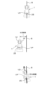
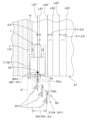
- the working device may be a reversible plow having a first frame connected to the lifting device, a second frame supported so as to be freely rotatable relative to the first frame, and a plurality of bottoms that are the working tools that are supported symmetrically above and below on the second frame and perform tilling work.
- the working machine is equipped with a travel device including a plurality of wheels
- the first control device defines the first travel route along which the working machine performs furrow digging using the reversible plow
- the previous work is opening plowing in which the reversible plow forms a furrow in the field extending in the working direction
- the reference position may be a position where the wheels of the working machine are aligned over a range extending in the working direction of the furrow, which is evidence of the opening plowing.
- the working machine is equipped with a traveling device including a plurality of wheels
- the first control device defines the first traveling route along which the working machine performs furrow digging using the reversible plow
- the previous work is the plowing work in which the reversible plow travels in the field in the working direction
- the reference position may be a position where the wheels of the working machine are aligned within a range extending in the working direction of a furrow portion, which is a trace of the plowing work.
- the first control device defines the first travel route along which the implement performs hill towing using the reversible plow, and the previous work is opening plowing in which the reversible plow forms a furrow in the field extending in the working direction
- the reference position may be a position where the extension of the furrow, which is evidence of the opening plowing, in the working direction is adjacent to the working range of the reversible plow.
- the first control device defines the first travel route along which the work machine performs hill towing using the reversible plow, the previous work is the plowing work in which the reversible plow travels in the field in the working direction, and the reference position may be a position where the extension of a furrow portion, which is evidence of the plowing work, in the working direction is adjacent to the working range of the reversible plow.
- the work support device may include an input device that receives setting input of information, the input device receives setting input of work information related to a work device possessed by the work machine, the previous work is work performed by a work device other than the work device possessed by the work machine, and the first control device may define the separation width based on the work information, and define the first travel route based on the separation width and the vehicle body position at the reference position.
- the previous work may be a ridge forming work in which a ridge forming device forms a ridge in the field, and the reference position may be a position where the running gear of the working machine is aligned with the ridge, which is a trace of the previous work.
- the input device may receive setting input of the working width of the working device and the ridge width of the ridges as the work information, and the first control device may define the first travel route including a plurality of the paths spaced apart by the separation width based on the working width and the ridge width.
- a working machine includes the above-mentioned work support device, the working machine, and a second control device that controls automatic traveling based on the first traveling route output from the output device.
- the work assistance method is a work assistance method for a work machine that includes a work machine, a detection device that detects a vehicle body position, a first control device that defines a first driving route for automatic driving in a field based on the vehicle body position, and a second control device that controls automatic driving based on the first driving route defined by the first control device, and includes a step of moving the work machine to a reference position based on evidence of a previous work performed in the field, and a step of the first control device defining the first driving route that passes through the vehicle body position based on the vehicle body position of the work machine at the reference position detected by the detection device.
- the above-mentioned work assistance device, work machine, and work assistance method allow for appropriate coordination between the previous work and the current work when performing work using automatic driving after the previous work.
- FIG. 11 is a diagram illustrating plowing work (ditching) in the first embodiment.
- FIG. 2 is a diagram illustrating plowing work (hill pulling) in the first embodiment.
- FIG. 4 is a diagram showing an example of a second travel route for plowing work in the first embodiment.
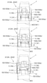
- 10A and 10B are diagrams illustrating fluctuations in the actual working width of the working implement during plowing work (ditch drawing) in the first embodiment.
- 11A and 11B are diagrams illustrating fluctuations in the actual working width of the working implement during plowing work (hill pulling) in the first embodiment.
- 5 is a flowchart showing an example of a process for defining a first travel route in the first embodiment.
- FIG. 4 is a diagram illustrating a reference position in plowing work (ditch drawing) in the first embodiment.
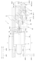
- the work machine 1 comprises a vehicle body 3 (machine body), a prime mover 4, a transmission 5, and a traveling device 7.
- vehicle body 3 supports various devices (on-board devices) provided on the work machine 1.
- the vehicle body 3 is provided with a driver's seat 10 and a protection mechanism for protecting the driver's seat 10 (e.g., a cabin, canopy, LOPs, etc.).
- a work device 2 that performs work in a field H is connected to the vehicle body 3.
- a lifting device 3a that connects the work device 2 so that it can be raised and lowered is provided to the front and/or rear of the vehicle body 3.
- the lifting device 3a is provided at the rear of the vehicle body 3, and connects the work device 2 to the rear of the vehicle body 3.
- the lifting device 3a is composed of, for example, a three-point link mechanism, and is capable of raising and lowering the connected work device 2.
- the lifting device 3a is operated by a hydraulic cylinder, which is a hydraulic actuator, and raises and lowers the connected work device 2. Therefore, by connecting the work device 2 to the lifting device 3a, the work device 2 is equipped to the work machine 1.
- the working equipment 2 includes a tilling equipment for tilling, a tilling equipment for tilling, a ridge forming equipment for making ridges, a fertilizer spreading equipment for spreading fertilizer, a pesticide spreading equipment 2B for spreading pesticides to control pests, a seed spreading equipment for sowing, a transplanter for planting crops (seedlings), a harvesting equipment for harvesting crops, a harvesting equipment for harvesting grass, etc., a spreading equipment for spreading grass, etc., a grass collecting equipment for collecting grass, etc., a shaping equipment for shaping grass, etc.
- the operator can select from various types of working equipment 2 as described above and connect the selected working equipment 2 to the lifting equipment 3a.
- a tractor equipped with a tilling equipment (reversible plow 2A) is shown as an example of the working equipment 2.
- the working device 2 may be operated by power transmitted from the PTO shaft 5a described below, or may have a hydraulic device driven by hydraulic oil discharged from a hydraulic pump and be operated by the hydraulic device.
- the working device 2 may also have an electric actuator driven by supplied electricity and be operated by the electric actuator.
- the prime mover 4 is a power source that outputs power.
- the prime mover 4 is an engine (e.g., a diesel engine) or an electric actuator, etc.
- the transmission 5 can change the propulsive force of the traveling device 7 by changing gears, and can also switch the traveling device 7 between forward and reverse.
- the transmission 5 has multiple gears that transmit power, a shifter that changes the connection of the gears, and a clutch that switches between transmitting and disconnecting power, and the gears, shifters, clutches, etc. are used to switch the propulsive force of the traveling device 7, and switch between forward and reverse.
- the power generated by the prime mover 4 is transmitted to the traveling device 7 by the transmission 5, and the traveling device 7 is driven, causing the vehicle body 3 to travel forward and backward (forward AR1, backward AR2).
- the transmission 5 is provided with a PTO shaft 5a for transmitting (outputting) the power output by the prime mover 4 to the outside.
- the transmission 5 can switch between driving and stopping the PTO shaft 5a, for example, by a clutch, and the working device 2 connected to the PTO shaft 5a is driven by the power transmitted from the PTO shaft 5a.
- the traveling devices 7 are provided in pairs in the width direction and support the vehicle body 3 so that it can travel.
- the traveling devices 7 are provided with tire-type wheels (front wheels 7F and rear wheels 7R).
- the front wheels 7F and rear wheels 7R are tire-type, but they may also be crawler-type.
- the work machine 1 also includes a braking device 8 that applies the brakes to the traveling devices 7.
- the braking device 8 is a disc-type brake mechanism that can be switched between a braking state in which braking is applied and a release state in which braking is released.
- the work machine 1 includes a second control device 20, a second storage device 21, an operation device 22, a steering device 23, a second communication device 24, a detection device 25, and a sensing device 26.
- the second control device 20 is a processing circuit including one or more processors.
- the second control device 20 is a controller for the work machine 1 and performs various controls related to the work machine 1.
- the second control device 20 is communicably connected to various devices mounted on the work machine 1 via an in-vehicle network N such as CAN, ISOBUS, LIN, or FlexRay.
- the second control device 20 performs control processing (operation) of the prime mover 4 and the transmission 5, etc. based on a signal (operation signal) input from the operation device 22.
- the second control device 20 controls the drive, stop, and rotation speed of the prime mover 4.
- the second control device 20 controls the transmission 5 to switch the operating speed and operating direction of the travel device 7, change the vehicle speed of the work machine 1 (body 3), and switch between forward and reverse movement of the work machine 1.
- the steering device 23 includes a steering shaft and a power steering mechanism, and the steering shaft and power steering mechanism are used to change the direction of the front wheels 7F of the traveling device 7 to steer the vehicle body 3.
- the work machine 1 is capable of manual steering, in which the steering device 23 steers the vehicle body 3 in response to the operation of the steering wheel 23a, and automatic steering, in which the second control device 20 controls the steering device 23 to steer the vehicle body 3.
- the detection device 25 may also have an inertial measurement unit (IMU) including an acceleration sensor and a gyro sensor, etc.
- IMU inertial measurement unit
- the detection device 25 detects the roll angle, pitch angle, yaw angle, etc. of the vehicle body 3 using the inertial measurement unit. If the detection device 25 has an inertial measurement unit, it may correct the deviation of the vehicle body position VP relative to the work device 2 caused by the tilt of the vehicle body 3 based on the tilt information (roll angle, pitch angle, and yaw angle) of the vehicle body 3 detected by the inertial measurement unit (tilt correction function).
- tilt correction function tilt correction function
- FIG. 4 is a diagram illustrating the automatic travel of the work machine 1 in the first embodiment.
- the second control device 20 maintains the steering angle of the steering device 23, and when the vehicle body position VP deviates from the travel route R (when the position deviation between the travel route R and the vehicle body position VP is a predetermined value or more) as shown in the middle diagram of FIG. 4, the second control device 20 changes the steering angle of the steering device 23 so that the vehicle body position VP approaches the travel route R (so that the position deviation approaches zero).
- the second control device 20 controls automatic driving based on the driving route R, but the second control device 20 only needs to automatically perform at least steering based on the driving route R.
- the second control device 20 may automatically perform steering in the automatic mode, and leave driving to the operator (the driving is operated by the operator's manual driving), and perform automatic steering based on the driving route R.
- the sensing devices 26 include devices such as laser sensors like LiDAR, ultrasonic sensors, and cameras. Each sensing device 26 is installed at the front, rear, left and right sides of the vehicle body 3. Each sensing device 26 detects the presence or absence of an object around the work machine 1 and the distance to the object.
- the second control device 20 controls the transmission 5, braking device 8, steering device 23, etc. based on the output signal from each sensing device 26. For example, when an object is present in the traveling direction of the work machine 1 and the distance from the work machine 1 to the object is less than a predetermined value, the second control device 20 controls the transmission 5 and braking device 8 to slow down or stop the traveling device 7.
- the work support device 30 is a portable information processing device (computer), such as a tablet-type terminal device.
- the work support device 30 is mounted, for example, around the driver's seat 10 of the work machine 1, and is detachable from the work machine 1.
- the work machine 1 is equipped with a detachable work support device 30.
- the operator boards the work machine 1 in manual mode and operates the work machine 1 manually, the operator attaches the work support device 30 to the work machine 1.
- the work machine 1 in automatic mode is performing automatic travel and the operator is not boarding the work machine 1, it is preferable that the operator removes the work support device 30 from the work machine 1 and carries it with him.
- the work support device 30 includes a first control device 31, an input device 32, a first storage device (storage device) 33, and a first communication device 34.
- the first control device 31 is a processing circuit including one or more processors.
- the first control device 31 is a controller for the work support device 30 and performs various controls related to the work support device 30.
- the first control device 31 includes one or more memories, various analog circuits, various digital circuits, etc.
- the one or more memories store (store) software programs and various data to be executed by the one or more processors.
- the first control device 31 can read software programs from the one or more memories using the one or more processors and execute various processes based on the software programs.
- the first control device 31 may be capable of executing various processes based on a predetermined logic circuit using one or more processors, as described for the second control device 20. Also, the first control device 31 may be capable of executing various processes using multiple physically separated processors working together, as described for the second control device 20, and the configuration is not limited to the configuration described above.
- the input device 32 is an input interface that accepts information input operations (input of information settings).
- the input device 32 is, for example, a display operation device that displays various types of information on a screen and accepts operations on the information displayed on the screen.
- the input device 32 is a touch panel display, and accepts input of various information settings or instructions when the operator performs a predetermined operation on the input device 32.
- the input device 32 is a user interface and also serves as the display device of the work support device 30.
- the information input by the input device 32 is acquired by the first control device 31, which uses the information for various processes or stores it in the first storage device 33.
- the screen of the input device 32 is controlled by the first control device 31.
- the input device 32 has been described as an example of a display operation device that is a touch panel display, the input device 32 is not limited to a display operation device as long as it can at least accept input of information settings, and may be configured independently of the display device that displays various types of information.
- the first storage device 33 stores various information and data in a readable and writable manner.
- the first storage device 33 includes a non-volatile memory and the like.
- the first storage device 33 is communicatively connected to the first control device 31, and the first control device 31 can obtain the various information and data stored in the first storage device 33.
- the first communication device 34 is a communication interface of the work support device 30 and includes a communication circuit.
- the first communication device 34 can communicate wirelessly or wired with the second communication device 24 of the work machine 1.
- the first communication device 34 is, for example, a communication device that can communicate wirelessly with the second communication device 24 and performs wireless communication using Bluetooth (registered trademark) Low Energy in the specifications of Bluetooth (registered trademark) of the communication standard IEEE802.15.1 series, WiFi (registered trademark) of the communication standard IEEE802.11.n series, etc.
- the first control device 31 communicates with the second control device 20 of the work machine 1 via the first communication device 34 and the second communication device 24.
- the first communication device 34 may also be able to communicate wirelessly with the server device 100 via a public communication network such as the Internet. As a result, the first communication device 34 can input/output (transmit/receive) information, data, signals, etc. to/from the work machine 1 and the server device 100. In other words, the first communication device 34 also serves as an output device for the work support device 30. The first communication device 34 may be able to communicate with the work machine 1 via the server device 100.
- the first control device 31 acquires information that the input device 32 has accepted as an input operation. Specifically, for example, an operator operates the input device 32, which causes the input device 32 to accept input operations of various information, and the first control device 31 acquires the information. In addition, if various information input as settings by another information processing device is stored in the server device 100, the first control device 31 may acquire this information from the server device 100 via the first communication device 34. The first control device 31 stores this various information in the first storage device 33 or the memory of the first control device 31. For example, the first control device 31 acquires information (field information) of the field H in which the work implement 1 performs work, work information related to the agricultural work in the field H, machine information related to the work implement 1, and device information related to the work implement 2.
- information field information
- the field information includes information indicating the identification information, position, area, and field map M of the field H.
- the field information is information defined in association with each field H.
- the field map M indicates the contour OL of the field H and position information such as various areas set in the field H.
- the position, area, and field map M of the field H are defined by the first control device 31 or an information processing device other than the first control device 31 based on map information acquired from an external device such as the server device 100, or based on multiple vehicle positions VP periodically detected by the detection device 25 while the work machine 1 is traveling along the edge of the field H.
- the work information includes information about agricultural work to be performed in the field H.
- the work information is information that is defined in association with each field H.
- the work information includes, for example, work conditions, planned use of the work machine 1 and the work device 2, and a work plan.
- the headland is, for example, an area in which the working machine 1 turns, and is defined as the outer edge of the field H (such as around the ridges). It is up to the farmer to decide whether or not to cultivate crops in the headland.
- the working direction may also be specified by the farmer in a specific direction, may be defined based on the contour OL of the field H, or may be specified by the farmer at his/her discretion.
- the machine information includes information indicating the identification information, type, dimensional information, specifications, etc. of the work machine 1.
- the machine information includes information related to the work machine 1, excluding information related to the work device 2.
- the machine information may also be stored in the memory of the second control device 20 of the work machine 1.
- the device information includes information indicating the identification information, type, dimensional information, specifications, and first working width W1 (width of working range 2a, see FIG. 3) of the working device 2.
- the device information may also include a first offset amount WO1 (see FIG. 3) of the center of the width of the working device 2 relative to the center of the width of the vehicle body 3.
- the working device 2 may be provided with a memory, and the device information may also be stored in the memory.
- the information acquired by the first control device 31 is not limited to the above-mentioned information, and other information may be acquired.
- the first control device 31 can acquire the vehicle body position VP detected by the detection device 25 via the first communication device 34 and the second communication device 24.
- the first control device 31 stores the acquired vehicle body position VP as an actual result in the first storage device 33.
- the first control device 31 acquires the vehicle body position VP during automatic driving, and stores the vehicle body position VP in the first storage device 33 in association with the driving route R.
- the first control device 31 executes support processing to support the driving and work of the work machine 1 based on the acquired information. Specifically, the first control device 31 defines a driving route R. As shown in FIG. 1, the first control device 31 has a route definition unit 31a, which is, for example, a software program implemented in the first control device 31. As another example, the route definition unit 31a may be configured with hardware such as semiconductor elements and electric circuits, and provided in the work support device 30.
- the route definition unit 31a defines the path that the work machine 1 travels inside the field H as the travel route R.
- the route definition unit 31a defines the travel route R while simulating the work by the work machine 2 and the automatic travel by the work machine 1.
- the travel route R defined by the route definition unit 31a is output to the work machine 1 (second communication device 24) by the first communication device 34 (output device). This allows the second control device 20 of the work machine 1 to control the automatic travel based on the travel route R output from the output device 34.
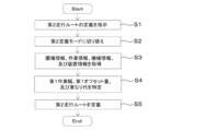
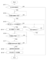
- FIG. 5 is a flowchart showing an example of a process for defining a travel route R executed by the work support device 30 in the first embodiment. Each step in FIG. 5 is executed by the first control device 31 in accordance with a software program stored in the memory or the first storage device 33.
- the route definition unit 31a performs the process shown in FIG. 5 to switch to the second definition mode, and defines the travel route R in the second definition mode.
- the travel route R defined by the route definition unit 31a in the second definition mode will be referred to as the second travel route R2.
- the operator operates the input device 32, causing the input device 32 to display a predetermined first setting screen, and the operator specifies (inputs) the field H, the agricultural work, the working machine 1 to be used, and the working device 2 on the first setting screen to instruct the definition of the travel route R (second travel route R2) (S1).
- the route definition unit 31a switches to a second definition mode that defines the second travel route R2 (S2), and acquires the field information, work information, machine information of the working machine 1, and device information of the working device 2 corresponding to the specified field H from at least one of the memory and the storage device 33, or from the server device 100 via the first communication device 34 (S3). That is, the first control device 31 acquires the field information, work information, machine information, and device information from at least one of the memory of the work support device 30 and the memory of the server device 100.
- the route definition unit 31a identifies the first working width W1, the first offset amount WO1, and the overlapping amount WR1 of the work device 2 from the device information of the work device 2 (S4).
- the route definition unit 31a defines the second travel route R2 based on the acquired information (S5).
- the route definition unit 31a defines the second travel route R2 with the following goals: (P1) the work machine 1 does not travel through worked areas as much as possible, (P2) avoid setting turning sections where the work machine 1 needs to turn around as much as possible, and (P3) shorten as much as possible the non-working distance, which is the distance the work machine 1 travels without performing work with the work device 2.
- the route definition unit 31a defines the second travel route R2, it associates the defined second travel route R2 with the identification information of the field H and stores it in the first storage device 33. At this time, the route definition unit 31a may also associate work information, machine information, and device information with the second travel route R2 in the first storage device 33, in addition to the identification information of the field H.
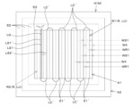
- the second travel route R2 includes a number of paths LS that each extend in the working direction of the field H and are spaced apart by a predetermined second separation width WS2.
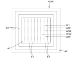
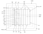
- Figure 6 is a diagram showing an example of the second travel route R2 defined in the field map M in the first embodiment.
- the route definition unit 31a defines, for example, as the second travel route R2, a headland route LO for working in the second area A2 and an inner route LU for working in the first area A1.
- the second area A2 is defined so as to extend from the contour OL of the field H to the inside of the field H, and the headland route LO includes one or more travel lines LOn (circumnavigation lines) along which the work implement 1 travels in the second area A2.
- the number of circumnavigation lines LOn of the headland route LO corresponds to the number of headlands n.
- the route definition unit 31a defines the headland route LO on the field map M included in the field information based on the number of headlands n included in the acquired work information, the first working width W1 included in the device information, and the like.
- the route definition unit 31a shifts the contour OL (outer periphery) of the field H inward to define one or more circuit lines LOn within the second area A2. Furthermore, when the number of headlands n is multiple and multiple circuit lines LOn are defined, the route definition unit 31a defines the multiple circuit lines LOn so that the multiple circuit lines LOn are spaced apart by the second separation width WS2.
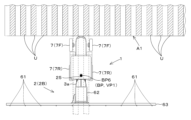
- FIG. 7A is a diagram for explaining the definition of the headland route LO in the first embodiment.
- the route definition unit 31a divides the second area A2 based on the first working width W1 to define an outer working section E2 (an area worked by the working device 2 when the working machine 1 travels along one circuit line LOn) in the second area A2, and defines a plurality of outer working sections E2 in the second area A2.
- the route definition unit 31a overlaps the first working width W1 with the outer working section E2 created one step earlier by an overlapping amount WR1 in the outer working section E2.
- the route definition unit 31a defines a circuit line LOn for each outer working section E2.
- the route definition unit 31a defines a circuit line LOn that passes on a line offset by a first offset amount WO1 from the center line in the width direction of the outer working section E2.
- the route definition unit 31a defines the first area A1 and the second area A2 based on the innermost circular line LOn and the first work width W1.
- the route definition unit 31a defines the inner route LU.
- the route definition unit 31a defines, as the inner route LU, multiple routes LS that extend in the work direction of the field H and are spaced apart by the second separation width WS2.
- the multiple routes are multiple work lines LS that connect both ends of the field H in the work direction and are each spaced apart by the second separation width WS2.
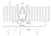
- FIG. 7B is a diagram for explaining the definition of the inner route LU in the first embodiment.
- the route definition unit 31a divides the first area A1 based on the first working width W1 to create an inner work section E1 (the range where the work device 2 works when the work machine 1 travels along one work line LS) in the first area A1, and defines multiple inner work sections E1 extending in the work direction in the first area A1.
- the route definition unit 31a overlaps the first working width W1 with the second area A2 by an overlapping amount WR1 in the first inner work section E1 defined by the route definition unit 31a.
- the first working width W1 overlaps the previously defined inner work section E1 by an overlapping amount WR1.
- the route definition unit 31a defines a work line LS for each inner work section E1.
- the work line LS is a substantially straight path.
- the route definition unit 31a defines a work line LS that passes along a line offset by a first offset amount WO1 from the center line in the width direction of the inner work section E1, for example.
- the route definition unit 31a also defines a connection line LC that connects adjacent work lines LS in the second area A2.
- the connection line LC is a route that is approximately curved. That is, in the example shown in FIG. 6, the headland route LO is the route that the work machine 1 travels around the second area A2 of the field H, and the inner route LU is the route that the work machine 1 travels back and forth to the first area A1.
- the first control device 31 (route definition unit 31a) defines a travel route R (first travel route R1) that passes through the reference vehicle body position VP1 based on the vehicle body position VP (hereinafter referred to as the reference vehicle body position VP1) when the work machine 1 moves to the reference position BP.
- the reference position BP is a position based on the traces of the previous work performed by the same work device 2 as the work device 2 used in the current work during automatic driving.
- the reference position BP is the position where the wheels 7F, 7R of the working machine 1 that have turned after opening plowing, and where the furrow G formed by opening plowing is located, are aligned on the range G'.
- the reference position BP is the position where the wheels 7F, 7R of the working machine 1 have turned after opening plowing and dropped into the furrow G.
- the work machine 1 is located in the first area A1 of the field H, and the wheels 7F, 7R of the work machine 1 are dropped into the groove G, but the reference position BP is not limited to the position where the wheels 7F, 7R of the work machine 1 are dropped into the groove G, and may be a position where at least the wheels 7F, 7R on the side where the groove G is located are aligned on the range G'.
- the wheels 7F, 7R may not be dropped into the groove G, but may be aligned just before the end of the groove G.
- the reference position BP is the position where the wheels 7F, 7R of the working machine 1 are aligned on the range G' obtained by extending the trace (furrow portion G) of the tilling work (the previous furrow drawing) in the working direction.
- the reference position BP is the position where the wheels 7F, 7R of the working machine 1 that have turned after the previous furrow drawing are aligned on the range G' on the side where the furrow portion G formed in the previous furrow drawing is located.
- the reference position BP is the position where the wheels 7F, 7R of the working machine 1 have turned after the previous furrow drawing and dropped into the furrow portion G, or the position where the wheels 7F, 7R have not dropped into the furrow portion G and are aligned just before the end of the furrow portion G.
- the reference position BP is the position where the range G' extending in the working direction of the furrow G, which is a trace of opening tillage, is adjacent to the working range 2a of the reversible plow 2A.
- the frontmost bottom 53 is located behind the wheels 7F, 7R on the furrow G side, by aligning the outer widthwise ends of the wheels 7F, 7R on the furrow G side with the end of the range G', the end of the frontmost bottom 53 on the furrow G side can be aligned with the end of the furrow G on the implement 1 side.
- the reference position BP is the position where the range G' obtained by extending the trace of open-mouth plowing (furrow G) of the front-most bottom 53 of the reversible plow 2A of the work machine 1 that has rotated after open-mouth plowing in the working direction is adjacent to the working range 2a.
- the reference position BP is the position of the work machine 1 when the end of the front-most bottom 53 on the furrow G side is aligned with the end of the furrow G on the work machine 1 side of the furrow G formed by open-mouth plowing.
- the reference position BP is the position of the work implement 1 when the end of the frontmost bottom 53 on the furrow G side and the end of the furrow G of the field H on the work implement 1 side are aligned.
- the work machine 1 can align the end of the working range 2a of the reversible plow 2A on the groove G side with the groove G formed in the previous operation.
- the route definition unit 31a acquires the vehicle body position VP (reference vehicle body position VP1) detected by the detection device 25 at the reference position BP via the first communication device 34 and the second communication device 24 (S18).
- the route definition unit 31a acquires the reference vehicle body position VP1 (S18)
- it defines a first driving route R1 based on the reference vehicle body position VP1 (S19).
- the route definition unit 31a corrects the second travel route R2 based on the deviation ⁇ D (position deviation) of the reference vehicle body position VP1 relative to the second travel route R2 to define the first travel route R1.
- the route definition unit 31a calculates the shortest distance between the extracted current work line LS1 (hereinafter referred to as the first work line) and the reference vehicle body position VP1, and calculates the deviation ⁇ D of the reference vehicle body position VP1 relative to the first work line LS1.
- the deviation ⁇ D is the distance between the first work line LS1 and a virtual straight line that passes through the reference vehicle body position VP1 and extends in the work direction, and is the length in the direction perpendicular to the work direction.
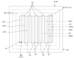
- FIG. 19 is a diagram for explaining the definition of the first travel route R1 in the first embodiment.
- the route definition unit 31a corrects the work line LSm from the current time onwards extracted from the second travel route R2 to define the first travel route R1 including multiple paths LSm' (work lines after correction) spaced apart by a first separation width WS1 obtained by subtracting the overlapping width WR1 from the first work width W1.
- the first separation width WS1 is a width calculated as the difference between the working width W4 (estimated actual working width, fourth working width) estimated from the third working width W3 and the overlapping width WR1.
- the fourth working width W4 can be calculated based on the above-mentioned deviation ⁇ D and the first working width W1 using the following formula (1).
- 4th working width W4 1st working width W1-2 ⁇ D...Formula (1)
- ⁇ D is the deviation of the reference vehicle body position VP1 from the first work line LS1.
- the first separation width WS1 is calculated as the difference between the fourth work width W4 and the overlapping amount WR1
- the second separation width WS2 is calculated as the difference between the first work width W1 and the overlapping amount WR1, so the difference between the first separation width WS1 and the second separation width WS2 is twice the deviation ⁇ D.
- the route definition unit 31a defines the first separation width WS1 and performs a correction to shift each work line LS in a direction closer to the reference vehicle body position VP1 so that the work lines LS from this time onwards are separated by the first separation width WS1 (the value obtained by subtracting twice the deviation ⁇ D from the second separation width WS2).
- the route definition unit 31a performs a correction to shift the first work line LS1 by the deviation ⁇ D in a direction toward the reference vehicle body position VP1.
- the route definition unit 31a corrects the extracted work lines LS by shifting the work line LS2 (second work line) next to the first work line LS1 by three times ⁇ D in a direction closer to the reference vehicle body position VP1. Also, the route definition unit 31a corrects the extracted work lines LS by shifting the work line LS3 (third work line) next to the second work line LS2 by five times ⁇ D in a direction closer to the reference vehicle body position VP1.
- the route definition unit 31a When the route definition unit 31a makes a correction to shift the extracted work line LS, it redefines a connecting line LC' that connects adjacent corrected work lines LSm', and defines a first driving route R1.
- the route definition unit 31a defines the first driving route R1
- it stores the first driving route R1 in the first storage device 33
- the first communication device 34 outputs the first driving route R1 to the second control device 20 via the second communication device 24. This allows the second control device 20 to control automatic driving based on the first driving route R1 defined by the route definition unit 31a based on the reference vehicle body position VP1.
- the process for defining the first travel route R1 described using FIG. 13 is merely an example, and is not limited to the above-mentioned definition process.
- the process of S11 may be omitted, and the route definition unit 31a may define the first travel route R1 even when the work device 2 is a work device 2 other than the first type work device (e.g., a pesticide spraying device 2B).
- the mode change switch is operated to switch the work machine 1 to manual mode, but the work machine 1 may be configured to automatically switch to manual mode when the vehicle body position VP travels along the connection line LC and arrives at the first work line LS1 (for example, when the vehicle body position VP reaches the middle of the connection line LC or the start point of the first work line LS1 or its vicinity).
- the route definition unit 31a may display the setting operation key in an active state if it determines that the work machine 1 is in manual mode and that the vehicle body orientation VD matches the work direction, and may display the setting operation key in a deactive state if it determines that the work machine 1 is in automatic mode or that the vehicle body orientation VD does not match the work direction.
- the first separation width WS1 can be calculated by subtracting twice the deviation ⁇ D from the second separation width WS2. Therefore, when the route definition unit 31a defines the first traveling route R1 by correcting the second traveling route R2 using the procedure described above, if an unworked area may occur within the first area A1, the route definition unit 31a can define a new work line LS based on the first separation width WS1 (fourth working width W4 and overlap WR1).
- the first travel route R1 only needs to include multiple routes LSm' that pass through the reference vehicle body position VP1 and are spaced apart by the first separation width WS1, and the method of defining the first travel route R1 by the route definition unit 31a is not limited to the method described above.
- the route definition unit 31a may define a subsequent work line LSm' based on the fourth work width W4 derived by the above-mentioned formula (1).
- the route definition unit 31a may define the first work line LS1 of the first traveling route R1 by correcting the first work line LS1 of the second traveling route R2 by shifting the first work line LS1 by an offset ⁇ D in a direction toward the reference vehicle body position VP1, or may define a new work line LS that passes through the reference vehicle body position VP1 and extends in the work direction.
- the route definition unit 31a divides the first area A1 based on the fourth working width W4 to create an inner work section E1' in the first area A1, and defines a plurality of inner work sections E1' extending in the work direction in the first area A1.
- the route definition unit 31a defines the first inner work section E1' as a work line LS' that passes through the reference vehicle body position VP1 and extends in the work direction, and defines the first inner work section E1'.
- the route definition unit 31a calculates an unworked area of the field H based on the reference position BP and the fourth working width W4, and defines the second and subsequent inner work sections E1' in the unworked area. At this time, the route definition unit 31a overlaps the fourth working width W4 with the inner work section E1' defined one step earlier by an overlapping allowance WR1.
- the route definition unit 31a defines a work line LS' for each inner work section E1', in the same way as when defining the second travel route R2, and defines a connection line LC' that connects adjacent work lines LS'.
- the route definition unit 31a divided the first area A1 into inner work sections E1 and defined a driving route R that travels through the entire inner work section E1.
- the route definition unit 31a defines the first travel route R1 based on the second travel route R2.
- the operator may operate the work machine 1 in manual mode to perform the previous work, and the route definition unit 31a may newly define the first travel route R1 that passes through the reference vehicle position VP1 and includes multiple routes LSm' spaced apart by the first separation width WS1.
- the route definition unit 31a may first define the second driving route R2 in the second definition mode and then correct the second driving route R2, or may define a new first driving route R1 separately from the second driving route R2. First, a case will be described in which the route definition unit 31a corrects the second driving route R2 to define the first driving route R1.
- the reference position BP is sufficient as long as it is a position where the traveling device 7 is aligned with at least the ridges U that are the evidence of the ridge-making work, and the working machine 1 may be located within the first area A1, as at point BP6 in FIG. 24, or may be located outside the first area A1, as at point BP7 in FIG. 25.
- the work support device 30 when the work machine 1 automatically travels along the first travel route R1, the work can be performed appropriately along the traces of the previous work. Furthermore, even if the work machine 1 has a work device 2 whose first work width W1 varies due to factors such as the state of the field H, the separation width WS1 can be appropriately defined.
- a work machine 1 comprising: the work support device 30 described in item 4; the work device 2; and a second control device 20 that controls automatic traveling based on the first traveling route R1 output from the output device 34.
- the swing angle of the work machine 2 may change in response to the condition of the field H, causing the actual working width W3 to vary.
- the first control device 31 can appropriately define the separation width WS1 in response to changes in the actual working width W3, and therefore can define the first traveling route R1 that prevents the occurrence of unworked areas where the work machine 1 performing automatic traveling does not perform any work, and prevents unnecessary overlapping work.
- the implement 1 according to item 8 can appropriately perform tilling work using the reversible plow 2A while preventing the occurrence of unworked areas and unnecessary overlapping work.
- the work machine 1 described in item 8 is equipped with a traveling device 7 including a plurality of wheels 7F, 7R, the first control device 31 defines the first traveling route R1 along which the work machine 1 performs furrow digging using the reversible plow 2A, the preliminary work is opening plowing in which the reversible plow 2A forms a furrow portion G extending in the working direction in the field H, and the reference position BP is a position where the wheels 7F, 7R of the work machine 1 are aligned over a range G' extending in the working direction of the furrow portion G, which is a trace of the opening plowing.
- the working machine 1 described in item 8 is equipped with a traveling device 7 including a plurality of wheels 7F, 7R, the first control device 31 defines the first traveling route R1 along which the working machine 1 performs furrow digging using the reversible plow 2A, the previous work is the plowing work in which the reversible plow 2A travels in the working direction in the field H, and the reference position BP is a position where the wheels 7F, 7R of the working machine 1 are aligned over a range G' obtained by extending a furrow portion G, which is a trace of the plowing work, in the working direction.
- the work machine 1 according to item 10 can define a first travel route R1 for trenching that prevents the occurrence of unworked areas and unnecessary overlapping work.
- the first control device 31 defines the first travel route R1 along which the work machine 1 performs hill pulling using the reversible plow 2A, the previous work is opening plowing in which the reversible plow 2A forms a furrow G extending in the working direction in the field H, and the reference position BP is a position where the range G' of the furrow G, which is evidence of the opening plowing, extended in the working direction is adjacent to the working range 2a of the reversible plow 2A.
- the first control device 31 defines the first travel route R1 along which the work machine 1 performs hill pulling using the reversible plow 2A, the previous work is the plowing work in which the reversible plow 2A travels in the work direction in the field H, and the reference position BP is a position where the range G' obtained by extending in the work direction the furrow portion G, which is a trace of the plowing work, is adjacent to the work range 2a of the reversible plow 2A.
- the work machine 1 according to item 11 can define a first travel route R1 for hill towing that prevents the occurrence of unworked areas and unnecessary overlapping work.
- the work support device 30 described in item 3 is equipped with an input device 32 that accepts setting input of information, the input device 32 accepts setting input of work information related to a work device 2 possessed by the work machine 1, the previous work is work performed by a work device 2 other than the work device 2 possessed by the work machine 1, and the first control device 31 defines the separation width WS1 based on the work information, and defines the first driving route R1 based on the separation width WS1 and the vehicle body position VP at the reference position BP.
- the work support device 30 when the work machine 1 automatically travels along the first travel route R1, it can perform work appropriately according to the location of traces of the previous work.
- the first travel route R1 is defined according to the actual positional relationship between the travel device 7 and the ridge U, so that when the work machine 1 automatically travels along the first travel route R1, the positional relationship between the travel device 7 and the ridge U can be appropriately maintained.
- the input device 32 accepts setting input of the first working width W1 of the work device 2 and the ridge width WU of the ridge U as the work information, and the first control device 31 defines the first travel route R1 including multiple paths LSm' separated by the separation width WS1 based on the first working width W1 and the ridge width WU.
- the work route is defined based on the separation width WS1 taking into account the first working width W1 and the ridge width WU in addition to the actual positional relationship between the traveling device 7 and the ridge U, so the work machine 1 can travel while properly maintaining the positional relationship between the traveling device 7 and the ridge U while suppressing the occurrence of unworked areas and unnecessary overlapping work.
- a work machine 1 including: a work support device 30 according to any one of items 13 to 15; the work device 2; and a second control device 20 that controls automatic traveling based on the first traveling route R1 output from the output device 34.
- the work machine 1 according to item 16 can achieve the unique effects described above, and the work machine 1 can appropriately perform the work after the previous work.
- a work assistance method for a work machine 1 comprising a work machine 2, a detection device 25 that detects a vehicle body position VP, a first control device 31 that defines a first driving route R1 for automatic driving in a field H based on the vehicle body position VP, and a second control device 20 that controls automatic driving based on the first driving route R1 defined by the first control device 31,
- the work assistance method comprising the steps of: moving the work machine 1 to a reference position BP based on evidence of previous work performed in the field H; and defining the first driving route R1 that passes through the vehicle body position VP based on the vehicle body position VP of the work machine 1 at the reference position BP detected by the detection device 25.
- the work machine 1 can appropriately link the previous work and the current work by performing the work by automatic travel based on the first travel route R1 after the previous work.
Landscapes
- Engineering & Computer Science (AREA)
- Life Sciences & Earth Sciences (AREA)
- Mechanical Engineering (AREA)
- Soil Sciences (AREA)
- Environmental Sciences (AREA)
- Aviation & Aerospace Engineering (AREA)
- Radar, Positioning & Navigation (AREA)
- Remote Sensing (AREA)
- Physics & Mathematics (AREA)
- General Physics & Mathematics (AREA)
- Automation & Control Theory (AREA)
- Guiding Agricultural Machines (AREA)
Abstract
Lorsqu'un travail doit être effectué par déplacement automatique après un travail antérieur, la présente invention relie de manière appropriée le travail antérieur et le présent travail. Ce dispositif de support de travail (30) comprend : un premier dispositif de commande (31) qui, sur la base d'une position de véhicule de machine de travail (VP) détectée par un dispositif de détection (25) disposé sur la machine de travail (1) comprenant un dispositif de travail (2), définit un premier itinéraire de déplacement (R1) pour que l'engin de chantier se déplace automatiquement dans un champ (H) ; et un dispositif de sortie (34) qui délivre le premier itinéraire de déplacement défini par le premier dispositif de commande à l'engin de chantier. Le premier dispositif de commande définit le premier itinéraire de déplacement qui passe à travers la position du véhicule sur la base de la position du véhicule lorsque l'engin de chantier s'est déplacé vers une position de référence (BP) pour laquelle des traces de travail antérieur effectuées dans le champ servent de référence.
Applications Claiming Priority (2)
| Application Number | Priority Date | Filing Date | Title |
|---|---|---|---|
| JP2023-221433 | 2023-12-27 | ||
| JP2023221433 | 2023-12-27 |
Publications (1)
| Publication Number | Publication Date |
|---|---|
| WO2025142702A1 true WO2025142702A1 (fr) | 2025-07-03 |
Family
ID=96218959
Family Applications (1)
| Application Number | Title | Priority Date | Filing Date |
|---|---|---|---|
| PCT/JP2024/044897 Pending WO2025142702A1 (fr) | 2023-12-27 | 2024-12-19 | Dispositif de support de travail, machine de travail et procédé de support de travail |
Country Status (1)
| Country | Link |
|---|---|
| WO (1) | WO2025142702A1 (fr) |
Citations (3)
| Publication number | Priority date | Publication date | Assignee | Title |
|---|---|---|---|---|
| JP2002181566A (ja) * | 2000-12-19 | 2002-06-26 | Yanmar Agricult Equip Co Ltd | 農業用作業車 |
| JP2020101964A (ja) * | 2018-12-21 | 2020-07-02 | ヤンマーパワーテクノロジー株式会社 | 走行状態表示装置、及び、自動走行システム |
| JP2020160531A (ja) * | 2019-03-25 | 2020-10-01 | ヤンマーパワーテクノロジー株式会社 | 作業車両用の目標経路生成システム |
-
2024
- 2024-12-19 WO PCT/JP2024/044897 patent/WO2025142702A1/fr active Pending
Patent Citations (3)
| Publication number | Priority date | Publication date | Assignee | Title |
|---|---|---|---|---|
| JP2002181566A (ja) * | 2000-12-19 | 2002-06-26 | Yanmar Agricult Equip Co Ltd | 農業用作業車 |
| JP2020101964A (ja) * | 2018-12-21 | 2020-07-02 | ヤンマーパワーテクノロジー株式会社 | 走行状態表示装置、及び、自動走行システム |
| JP2020160531A (ja) * | 2019-03-25 | 2020-10-01 | ヤンマーパワーテクノロジー株式会社 | 作業車両用の目標経路生成システム |
Similar Documents
| Publication | Publication Date | Title |
|---|---|---|
| JP7355902B2 (ja) | 作業車両用の自動走行システム及び作業車両の制御方法 | |
| JP7353877B2 (ja) | 作業車両及び作業車両の作業支援装置 | |
| JP7657950B2 (ja) | 農業機械の走行支援システム | |
| WO2017026080A1 (fr) | Procédé de conception d'itinéraire pour véhicule autonome | |
| WO2021125124A1 (fr) | Machine de travail | |
| US12369508B2 (en) | Travel line creation system for agricultural machine | |
| JP2023001289A (ja) | 作業機、及び、作業機の自動走行制御システム | |
| JP2024105317A (ja) | 領域調整システム | |
| JP7669394B2 (ja) | 農業機械の走行支援システム | |
| JP7106419B2 (ja) | 作業車両 | |
| JP7330878B2 (ja) | 作業機 | |
| JP7793759B2 (ja) | 農作業支援システム、農業機械、農作業支援装置、農業機械の走行ルート作成方法 | |
| WO2025142702A1 (fr) | Dispositif de support de travail, machine de travail et procédé de support de travail | |
| JP7600095B2 (ja) | 農業機械、農作業支援システム | |
| AU2022333603B2 (en) | Work machine | |
| JP7746252B2 (ja) | 農作業支援装置、農作業支援システム、農業機械、走行ライン作成方法 | |
| JP6788229B2 (ja) | 圃場作業車の自動操舵装置 | |
| JP7822924B2 (ja) | 農作業支援装置、農業機械 | |
| JP7805915B2 (ja) | 農作業支援装置、農作業支援システム、農業機械、走行ライン作成方法 | |
| WO2025142701A1 (fr) | Dispositif d'aide au travail, engin de chantier et procédé d'aide au travail | |
| JP2025099863A (ja) | 走行支援システム | |
| JP2026035000A (ja) | 作業車両 | |
| WO2024135025A1 (fr) | Système d'aide au travail agricole et machine agricole | |
| JP2025099481A (ja) | 作業支援装置、作業機、及び作業支援方法 | |
| JP2025173255A (ja) | 作業車両、作業支援システム |
Legal Events
| Date | Code | Title | Description |
|---|---|---|---|
| 121 | Ep: the epo has been informed by wipo that ep was designated in this application |
Ref document number: 24912591 Country of ref document: EP Kind code of ref document: A1 |
|
| ENP | Entry into the national phase |
Ref document number: 2025566636 Country of ref document: JP Kind code of ref document: A |
|
| WWE | Wipo information: entry into national phase |
Ref document number: 2025566636 Country of ref document: JP |