BRPI0919660B1 - METHOD FOR TIN SHELL FORMATION - Google Patents
METHOD FOR TIN SHELL FORMATION Download PDFInfo
- Publication number
- BRPI0919660B1 BRPI0919660B1 BRPI0919660-9A BRPI0919660A BRPI0919660B1 BR PI0919660 B1 BRPI0919660 B1 BR PI0919660B1 BR PI0919660 A BRPI0919660 A BR PI0919660A BR PI0919660 B1 BRPI0919660 B1 BR PI0919660B1
- Authority
- BR
- Brazil
- Prior art keywords
- mold
- center
- annular
- air
- extension
- Prior art date
Links
- 238000000034 method Methods 0.000 title claims abstract description 15
- 230000015572 biosynthetic process Effects 0.000 title claims description 8
- 229910052751 metal Inorganic materials 0.000 claims description 8
- 239000002184 metal Substances 0.000 claims description 8
- 230000002093 peripheral effect Effects 0.000 claims description 4
- 230000002459 sustained effect Effects 0.000 claims 1
- ATJFFYVFTNAWJD-UHFFFAOYSA-N Tin Chemical compound [Sn] ATJFFYVFTNAWJD-UHFFFAOYSA-N 0.000 abstract description 8
- 239000011521 glass Substances 0.000 abstract description 2
- 238000004519 manufacturing process Methods 0.000 description 4
- 125000006850 spacer group Chemical group 0.000 description 4
- 229910052782 aluminium Inorganic materials 0.000 description 3
- XAGFODPZIPBFFR-UHFFFAOYSA-N aluminium Chemical compound [Al] XAGFODPZIPBFFR-UHFFFAOYSA-N 0.000 description 3
- 230000020169 heat generation Effects 0.000 description 2
- 238000010438 heat treatment Methods 0.000 description 2
- 239000000463 material Substances 0.000 description 2
- 230000004048 modification Effects 0.000 description 2
- 238000012986 modification Methods 0.000 description 2
- 238000007789 sealing Methods 0.000 description 2
- 238000005452 bending Methods 0.000 description 1
- 230000000295 complement effect Effects 0.000 description 1
- 230000006835 compression Effects 0.000 description 1
- 238000007906 compression Methods 0.000 description 1
- 238000010276 construction Methods 0.000 description 1
- 239000011888 foil Substances 0.000 description 1
- 238000013467 fragmentation Methods 0.000 description 1
- 238000006062 fragmentation reaction Methods 0.000 description 1
- 238000010348 incorporation Methods 0.000 description 1
- 230000000977 initiatory effect Effects 0.000 description 1
- 238000012423 maintenance Methods 0.000 description 1
- 230000013011 mating Effects 0.000 description 1
Images


Classifications
-
- B—PERFORMING OPERATIONS; TRANSPORTING
- B21—MECHANICAL METAL-WORKING WITHOUT ESSENTIALLY REMOVING MATERIAL; PUNCHING METAL
- B21D—WORKING OR PROCESSING OF SHEET METAL OR METAL TUBES, RODS OR PROFILES WITHOUT ESSENTIALLY REMOVING MATERIAL; PUNCHING METAL
- B21D22/00—Shaping without cutting, by stamping, spinning, or deep-drawing
- B21D22/20—Deep-drawing
- B21D22/24—Deep-drawing involving two drawing operations having effects in opposite directions with respect to the blank
Landscapes
- Engineering & Computer Science (AREA)
- Mechanical Engineering (AREA)
- Shaping Metal By Deep-Drawing, Or The Like (AREA)
- Braking Arrangements (AREA)
- Fluid-Damping Devices (AREA)
Abstract
método para formação de concha de lata conchas de lata são produzidas com ferramenta! instalado numa prensa mecânica de movimento único, sendo que o ferramental inclui um retentor superior que acomoda um molde de corte e repuxo, este acomodando uma extensão de pressão externa e uma extensão de pressão interna circunvizinhando uma vareta de corte do centro do molde, todos dotados de pistões operados por ar. o pistão central do molde é dotado de reservatório de ar conectado por passagens de ar que formam espirais de ar destinadas à extensão de pressão interna, e a extensão de pressão externa recebe o mesmo ar controlável recebido pelo reservatório ou baixa pressão de fonte de suprimento de ar. a extensão de pressão interna é dotada de porção em formato de nariz que dá início ao repuxo de um copo, tendo superfícies contornadas que se encaixam com superfícies correspondentes num anel do centro do molde com propósito de formação e fixação da parede anular de fixação da concha durante o movimento descendente da prensa. uma vareta inferior de corte do painel forma o painel central, a parede do painel e o alargamento anular em formato de funil da concha durante o movimento ascendente da prensa.method for forming tin shells tin shells are produced with tools! installed in a single-motion mechanical press, and the tooling includes an upper retainer that accommodates a cutting and drawing mold, which accommodates an external pressure extension and an internal pressure extension surrounding a cutting rod in the center of the mold, all equipped of air operated pistons. the central piston of the mold is provided with an air reservoir connected by air passages that form air spirals for the internal pressure extension, and the external pressure extension receives the same controllable air received by the reservoir or low pressure from the air supply source. air. the internal pressure extension is equipped with a nose-shaped portion that initiates the drawing of a glass, having contoured surfaces that fit with corresponding surfaces in a ring in the center of the mold for the purpose of forming and fixing the annular shell fixation wall during the downward movement of the press. a lower panel cutting rod forms the central panel, the panel wall and the funnel-shaped annular widening of the shell during the upward movement of the press.
Description
[001] Esta invenção se refere a método para formação de concha de lata a partir de uma folha de metal ou de alumínio, por exemplo, tal como os métodos e aparelho ou ferramental divulgados nas patentes americanas de números 4.713.958, 4.716.755, 4.808.052, 4.955.223, 6.658.911 e 7.302.822. A divulgação destas patentes fica a esta incorporada como referência para complementação da descrição detalhada da presente invenção.[001] This invention relates to a method for forming a tin shell from a metal or aluminum foil, for example, such as the methods and apparatus or tooling disclosed in US patents numbers 4,713,958, 4,716,755 , 4,808,052, 4,955,223, 6,658,911 and 7,302,822. The disclosure of these patents is hereby incorporated as a reference to complement the detailed description of the present invention.
[002] No referido conjunto de ferramental ou aparelho, concluiu-se ser desejável que o aparelho fosse construído para uso numa prensa mecânica de movimento único tal como foi divulgado nas patentes acima mencionadas, de número 4.955.223 e 7.302.822, e para evitar o uso de prensa mecânica de movimento duplo, por exemplo, tal como descrito nas patentes acima mencionadas de números 4.716.755 e 6.658.911. Uma prensa de movimento único e alta velocidade é mais simples e econômica em sua construção, sendo ainda mais econômica quanto a operação e manutenção e pode ser operada de forma efetiva e eficiente, por exemplo, com um golpe de 1,75 polegada e numa velocidade de 650 golpes por minuto. Também existem muito mais prensas de movimento único e alta velocidade sendo utilizadas no ramo do que prensas de movimento duplo.[002] In the said tooling or apparatus set, it was concluded that it was desirable that the apparatus be built for use in a single motion mechanical press as disclosed in the above mentioned patents, numbering 4,955,223 and 7,302,822, and for avoid the use of a double-motion mechanical press, for example, as described in the aforementioned patents Nos. 4,716,755 and 6,658,911. A single-speed, high-speed press is simpler and more economical to build, being even more economical in terms of operation and maintenance and can be operated effectively and efficiently, for example, with a 1.75 inch stroke and at a speed of 650 strokes per minute. There are also many more single-motion and high-speed presses being used in the industry than double-motion presses.
[003] Concluiu-se ser desejável quanto ao aparelho ou ao conjunto de ferramental a incorporação de uma extensão (manga) de pressão interna e uma extensão (manga) de pressão externa e a operação de ambas as extensões com pressão de ar, porém evitando-se atuação da extensão de pressão interna através de molas que se estendem de forma axial, espaçadas em forma de circunferências como, por exemplo, divulgadas na patente de número 7.302.822 ou o uso de pinos que se estendem de forma axial e espaçados em forma de circunferências como, por exemplo, divulgado na patente de número 4.716.755. O movimento axial e de vai-e-vem em alta velocidade dos pinos e o pistão único que ativa os pinos dão origem a aquecimento adicional indesejável, sendo difícil produzir força axial, ajustável e de controle preciso, na extensão de pressão interna com a utilização de molas de compressão.[003] It was concluded that the incorporation of an internal pressure extension (sleeve) and an external pressure extension (sleeve) and the operation of both extensions with air pressure, while avoiding air pressure, - action of the internal pressure extension through springs that extend axially, spaced in the form of circumferences, as, for example, disclosed in patent number 7.302.822 or the use of pins that extend axially and spaced in form of circumferences, as, for example, disclosed in patent number 4,716,755. The axial and back-and-forth movement at high speed of the pins and the single piston that activates the pins give rise to undesirable additional heating, making it difficult to produce axial force, adjustable and precisely controlled, to the extent of internal pressure with use compression springs.
[004] É ainda desejável que se disponha de força constante, e controlada de forma precisa, exercida pela extensão de pressão externa sobre o material da folha para evitar o afinamento do material entre a extensão de pressão externa e o anel do centro do molde durante operação sob alta pressão da prensa. A pressão de ar, controlada de forma precisa, na extensão de pressão interna também é desejável para manutenção da parede anular de fixação da concha de lata enquanto se forma o alargamento anular em formato de funil, a parede do painel e o painel central da concha de lata sem que se afine a folha de metal. Adicionalmente, é desejável que se minimize a altura do conjunto de ferramental para a produção de conchas de lata a fim de se acomodar mais prensas de movimento único e alta velocidade, existentes no local, e para operá-las sob alta velocidade sem que se possa gerar mais aquecimento, com o propósito de evitar o uso de componentes esfriados por água no ferramental. Após revisão das patentes aqui mencionadas anteriormente, fica evidente que nenhuma delas proporciona as características acima desejáveis.[004] It is still desirable to have constant and precisely controlled force exerted by the extension of external pressure on the sheet material to prevent thinning of the material between the external pressure extension and the center ring of the mold during operation under high pressure of the press. Air pressure, precisely controlled, in the internal pressure extension is also desirable for maintaining the annular wall fixing the can ladle while forming the funnel-shaped annular widening, the panel wall and the central panel of the ladle of tin without the metal sheet being sharpened. Additionally, it is desirable to minimize the height of the tooling set for the production of tin shells in order to accommodate more single-motion and high-speed presses, existing on site, and to operate them at high speed without being able to generate more heating, in order to avoid the use of water-cooled components in the tooling. After reviewing the patents mentioned above, it is evident that none of them provides the above desirable characteristics.
[005] A presente invenção é direcionada ao método aperfeiçoado para produção em alta velocidade de conchas de lata, e que proporcionam todas as características desejáveis anteriormente mencionadas. O conjunto de ferramental da presente invenção também é idealmente adequado para produção de concha de lata tal como divulgado na patente do depositante sob n°. 7.341.163 e no pedido de patente do depositante depositado sob n°. US-2005-0029269, cujas divulgações ficam aqui também incorporadas como referência. O método da invenção é adequado especialmente para uso numa prensa de movimento único e para a produção de conchas de lata uniformes e precisas, sob alta velocidade, e com geração mínima de aquecimento com o propósito de evitar mudança térmica do conjunto de ferramental durante a operação.[005] The present invention is directed to the improved method for high-speed production of tin shells, which provide all the desirable characteristics mentioned above. The tooling set of the present invention is also ideally suited for the production of tin ladle as disclosed in the applicant's patent under no. 7,341,163 and in the depositor's patent application filed under no. US-2005-0029269, the disclosures of which are also incorporated herein by reference. The method of the invention is particularly suitable for use in a single-motion press and for the production of uniform and precise tin shells, under high speed, and with minimal heat generation in order to avoid thermal change of the tooling set during operation .
[006] De acordo com uma versão da invenção, uma concha de lata é formada pelo conjunto de ferramental, incluindo uma extensão anular de pressão interna que está localizada dentro de uma extensão anular de pressão externa, e as duas extensões têm pistões incorporados dentro das câmaras anulares de pistão de ar correspondentes.[006] According to one version of the invention, a can ladle is formed by the tooling set, including an annular extension of internal pressure that is located within an annular extension of external pressure, and the two extensions have pistons incorporated inside the corresponding annular piston air chambers.
[007] A extensão de pressão externa é apoiada dentro de um molde anular de corte e repuxo fixado a um retentor superior, montado numa sapata do molde superior de uma prensa de movimento único. O retentor também acomoda um pistão do centro do molde, que pode ser acomodado para movimentação axial relativa, e o pistão do centro do molde acomoda uma vareta de corte, do centro do molde, dentro da extensão de pressão interna. O pistão do centro do molde possui uma parte central que define uma câmara de reservatório de ar, abastecida de ar através de um orifício sob pressão controlada. A câmara de reservatório de ar é conectada à câmara de ar do pistão destinado à extensão de pressão interna por uma diversidade de passagens alongadas de ar, em forma de circunferências. A câmara de ar do pistão destinada à extensão de pressão externa é abastecida de ar sob pressão controlada, e substancialmente inferior, através de um orifício separado no retentor superior. A extensão de pressão interna é dotada de uma porção anular, com formato de nariz, que normalmente se projeta a partir do pistão do centro do molde, dando início ao repuxo de um copo dentro de um disco de folha de metal, cortado pelo molde, preso entre a extensão de pressão externa e um anel do centro do molde, fixo e oposto, que é apoiado por um retentor inferior montado numa sapata fixa e inferior da prensa. A parte em formato de nariz da extensão de pressão interna e o anel do centro do molde são dotados de superfícies contornadas de encaixe, que formam uma parede anular de fixação no disco, sendo que a vareta de corte do centro do molde auxilia a extensão de pressão interna no acabamento do repuxo do copo, que é agarrado por uma vareta de corte do painel, apoiada dentro do anel do centro do molde. A vareta de corte do painel é dotada de uma superfície periférica contornada, que forma o painel central da concha e também a parede anular do painel e o alargamento anular em formato de funil. Noutra versão da invenção, a câmara de ar do pistão destinada à extensão de pressão externa é conectada por uma passagem de ar, que se estende até a câmara de reservatório de ar, de forma que a câmara de ar do pistão, destinada à extensão de pressão interna, e a outra câmara de ar do pistão, destinada à extensão de pressão externa, recebam a mesmo suprimento de ar de pressão controlada, desta forma, evitando a necessidade de dois suprimentos diferentes de ar, sob pressões diferentes, para operação do conjunto de ferramental na sapata superior do molde.[007] The external pressure extension is supported inside an annular cutting and drawing mold fixed to an upper retainer, mounted on a shoe of the upper mold of a single movement press. The retainer also accommodates a piston from the center of the mold, which can be accommodated for relative axial movement, and the piston from the center of the mold accommodates a cutting rod, from the center of the mold, within the internal pressure extension. The piston in the center of the mold has a central part that defines an air reservoir chamber, supplied with air through an orifice under controlled pressure. The air reservoir chamber is connected to the piston air chamber for the extension of internal pressure through a variety of elongated air passages, in the form of circumferences. The piston air chamber for external pressure extension is supplied with air under controlled pressure, and substantially lower, through a separate orifice in the upper retainer. The internal pressure extension is provided with an annular, nose-shaped portion, which normally protrudes from the piston in the center of the mold, initiating the drawing of a glass into a metal sheet disc, cut by the mold, stuck between the external pressure extension and a ring in the center of the mold, fixed and opposite, which is supported by a lower retainer mounted on a fixed and lower shoe of the press. The nose-shaped part of the internal pressure extension and the center ring of the mold are provided with contoured fitting surfaces, which form an annular fixing wall on the disk, and the cutting rod in the center of the mold assists in the extension of internal pressure at the finish of the fountain, which is gripped by a panel cutting rod, supported inside the center ring of the mold. The panel's cutting rod is provided with a contoured peripheral surface, which forms the central panel of the shell and also the annular wall of the panel and the annular widening in the shape of a funnel. In another version of the invention, the piston air chamber for the external pressure extension is connected by an air passage, which extends to the air reservoir chamber, so that the piston air chamber, intended for the extension of air internal pressure, and the other piston air chamber, intended for the extension of external pressure, receive the same supply of controlled pressure air, thus avoiding the need for two different air supplies, under different pressures, for operation of the set tooling on the top shoe of the mold.
[008] Outras características e vantagens da invenção tornar-se-ão evidentes a partir da descrição que segue, dos desenhos que a acompanham e das reivindicações apresentadas.[008] Other features and advantages of the invention will become apparent from the description that follows, the accompanying drawings and the claims presented.
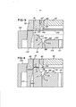
[009] A figura 1 é uma seção axial de um conjunto de ferramental construído e operado de acordo com a invenção.[009] Figure 1 is an axial section of a tooling set built and operated according to the invention.
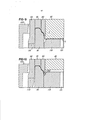
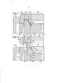
[010] A figura 2 é uma seção axial do conjunto de ferramental ilustrado na figura 1 e construído de acordo com uma modificação ou outra versão da invenção; e As figuras 3-12 são seções fragmentadas e ampliadas do conjunto de ferramental ilustrado nas figuras 1 e 2, ilustrando etapas de progressão para produção de uma concha de acordo com a invenção.[010] Figure 2 is an axial section of the tooling set illustrated in figure 1 and constructed according to a modification or other version of the invention; e Figures 3-12 are fragmented and enlarged sections of the tooling set illustrated in figures 1 and 2, illustrating progression steps for producing a shell according to the invention.
[011] Com referência à figura 12, uma concha (15) substancialmente ampliada é formada a partir de uma folha de metal ou alumínio, possuindo espessura de, aproximadamente, 0,0082 polegada. A concha (15) inclui um painel central, reto e circular, que é conectado por uma porção (17) de meio cone (cônica) ou anular afunilada, da parede do painel, e uma porção substancialmente cilíndrica (18), da parede do painel, a um alargamento anular em formato de funil (19), dotado de uma porção interna da parede (21) inclinada ou cônica (meio cone) e configuração geralmente em formato de "U" transversal. O alargamento anular em formato de funil (19) é dotado de parte externa da parede anular e levemente inclinada (22), conectada a uma porção inferior e anular da parede anular de fixação (23) e uma porção anular e superior da parede anular de fixação (24) dotada de configuração curvada e transversal. A porção superior e curvada da parede anular de fixação (24) se conecta a uma porção inclinada ou meio cone (cônica) anular interna da parede interna (26) de uma porção em formato de coroa (28), esta dotada de uma aba (29) externa, periférica e curvada.[011] With reference to figure 12, a substantially enlarged shell (15) is formed from a sheet of metal or aluminum, having a thickness of approximately 0.0082 inches. The shell (15) includes a central, straight and circular panel, which is connected by a tapered (conical) or tapered annular portion (17) of the panel wall, and a substantially cylindrical portion (18), of the wall. panel, to an annular widening in the shape of a funnel (19), provided with an internal portion of the wall (21) inclined or conical (half a cone) and configuration generally in the shape of a transversal "U". The funnel-shaped annular enlargement (19) is provided with an external part of the annular and slightly inclined wall (22), connected to a lower and annular portion of the annular fixation wall (23) and an annular and upper portion of the annular wall of fixation (24) with curved and transversal configuration. The upper and curved portion of the annular fixation wall (24) connects to a slanted portion or half cone (conical) of the inner annular wall (26) of a crown-shaped portion (28), this is provided with a flap ( 29) external, peripheral and curved.
[012] A configuração transversal ou perfil da concha (15) estão divulgados de forma mais específica no pedido americano de patente do presente depositante, já publicado e indicado anteriormente, sob n°. US-2005-0029269. Contudo, o método da invenção também podem ser adaptados para produção de conchas que tenham diferentes perfis.[012] The cross-sectional configuration or profile of the shell (15) are disclosed more specifically in the American patent application of the present depositor, already published and indicated previously, under no. US-2005-0029269. However, the method of the invention can also be adapted to produce shells having different profiles.
[013] Com relação à figura 1, um conjunto de ferramental (35) inclui um retentor anular superior (38), que é montado numa sapata do molde superior (40) de uma prensa mecânica de movimento único. O retentor (38) possui uma porção cilíndrica (41) que se projeta de forma ascendente numa cavidade de encaixe (42) da sapata do molde superior (40) e, assim, define uma câmara de ar pressurizado (44). Um molde anular de corte e repuxo (48) possui uma porção superior em forma de flange (49), que se projeta para fora, que é fixada ao retentor (38) por um conjunto de parafusos (51) espaçados em forma de circunferências. Um espaçador anular, reto e terra (52) é fixado à parte superior em formato de flange do molde de corte e repuxo (48), fazendo que o molde (48) seja espaçado de forma precisa e axial em relação ao retentor superior (38).[013] With reference to figure 1, a tooling set (35) includes an upper annular retainer (38), which is mounted on an upper mold shoe (40) of a single-motion mechanical press. The retainer (38) has a cylindrical portion (41) that projects upwardly into a socket (42) of the upper mold shoe (40) and thus defines a pressurized air chamber (44). An annular cutting and drawing mold (48) has an outwardly flanged upper portion (49), which is fixed to the retainer (38) by a set of screws (51) spaced in the shape of circumferences. An annular, straight and ground spacer (52) is attached to the upper flange-shaped part of the cutting and drawing mold (48), causing the mold (48) to be spaced precisely and axially in relation to the upper retainer (38) ).
[014] Uma extensão anular de pressão exterior (55) é acomodada para movimentação axial dentro do molde de corte e repuxo (48) e inclui um pistão formado em conjunto (56), dotado de pinos plásticos radiais de desgaste (57). Um pistão central (60) do molde pode ser acomodado para fins de movimentação axial dentro do retentor superior (38) e inclui uma porção inferior (62) que acomoda uma vareta de corte central do molde (65) fixada de forma removível ao pistão do centro do molde (60) por um parafuso da tampa central (66). Um espaçador anular (68), reto e terra, fica posicionado entre a vareta de corte do centro do molde (65) e uma parte em formato de ombro na parte inferior (62) do pistão do centro do molde (60) para fazer que a posição axial da vareta de corte, no pistão do centro do molde (60), seja selecionada de forma precisa. Uma câmara cilíndrica e pressurizada (70), de reservatório de ar, é formada na parte central do pistão do centro do molde (60), sendo fechada em cima por um pino dotado de rosca (71). A câmara reservatório (70) recebe ar pressurizado através de um orifício (74) formado dentro do retentor (38) e uma passagem radial alinhada (76) formada dentro do pistão do centro do molde (60).[014] An annular extension of external pressure (55) is accommodated for axial movement within the cutting and drawing mold (48) and includes a piston formed together (56), provided with radial plastic wear pins (57). A central piston (60) of the mold can be accommodated for axial movement purposes inside the upper retainer (38) and includes a lower portion (62) that accommodates a central cutting rod of the mold (65) removably fixed to the piston of the mold center (60) by a central cover screw (66). An annular spacer (68), straight and ground, is positioned between the cutting rod in the center of the mold (65) and a shoulder-shaped part at the bottom (62) of the piston in the center of the mold (60) to make the axial position of the cutting rod on the piston in the center of the mold (60) is precisely selected. A cylindrical and pressurized chamber (70), of air reservoir, is formed in the central part of the piston in the center of the mold (60), being closed at the top by a threaded pin (71). The reservoir chamber (70) receives pressurized air through an orifice (74) formed inside the retainer (38) and an aligned radial passage (76) formed inside the piston in the center of the mold (60).
[015] Uma extensão anular de pressão interna (80) é acomodada para fins de movimentação axial dentro da extensão de pressão externa (55), incluindo um pistão em conjunto (82) confinado dentro de uma câmara anular (84) de ar do pistão, definida de forma axial, entre o pistão (82) e uma porção axial em formato de ombro (86) na parte inferior (62) do pistão do centro do molde (60). A câmara de ar do pistão (84) recebe ar pressurizado através de uma diversidade de três passagens de ar (88), espaçadas em forma de circunferências, que se estendem de forma axial a partir da porção em formato de ombro (86) até a câmara de reservatório de ar (70 dentro do pistão do centro do molde (60). Anéis de vedação do ar, adequados e formados por duas peças, são transportados pelo pistão (82) da extensão de pressão interna (80) e também o pistão (56) da extensão de pressão externa (55), assim como também pela parte superior do pistão do centro do molde (60). O pistão (56) da extensão de pressão externa (55) fica confinado dentro de uma câmara anular de pressão do ar (89) que se estende até uma porção em formato de ombro de interrupção (90) e se conecta a uma câmara anular de ar (91). As câmaras (89 e 91) recebem ar pressurizado através de um orifício (92) do retentor (38).[015] An annular internal pressure extension (80) is accommodated for axial movement purposes within the external pressure extension (55), including a joint piston (82) confined within an annular chamber (84) of piston air , axially defined, between the piston (82) and an axial shoulder-shaped portion (86) at the bottom (62) of the piston in the center of the mold (60). The piston air chamber (84) receives pressurized air through a variety of three air passages (88), spaced in the form of circumferences, which extend axially from the shoulder-shaped portion (86) to the air reservoir chamber (70 inside the piston in the center of the mold (60). Air sealing rings, suitable and formed by two parts, are transported by the piston (82) of the internal pressure extension (80) and also the piston (56) of the external pressure extension (55), as well as the upper part of the piston in the center of the mold (60) .The piston (56) of the external pressure extension (55) is confined within an annular pressure chamber of the air (89) which extends to an interrupted shoulder-shaped portion (90) and connects to an annular air chamber (91) .The chambers (89 and 91) receive pressurized air through an orifice (92) of the retainer (38).
[016] O conjunto de ferramental (35) também inclui um retentor anular (94), inferior e fixo, que é montado numa sapata estacionária inferior do molde (95) da prensa de movimento único. O retentor inferior (94) acomoda um anel fixo do centro do molde (98) dotado de uma parte superior anular (99), e também acomoda um retentor anular fixo (102) que confina um molde anular de corte (105). Um espaçador reto (107), anular e terra, é fixado ao retentor (102) para fins de confinar o molde anular de corte (105) e faz que se posicione de forma precisa e axial o molde de corte com relação à parte superior anular (99) do anel do centro do molde (98). Uma extensão anular inferior de pressão (110) fica posicionada entre o molde de corte (105) e a parte superior (99) do anel do centro do molde (98) e possui um pistão em conjunto (112) acomodado para fins de movimentação axial dentro de uma câmara pressurizada e anular de pressão de ar (114) definida entre o retentor inferior (94) e o anel do centro do molde (98). A câmara (114) recebe ar pressurizado através de um orifício (não ilustrado) com o retentor inferior (94). Uma vareta de corte circular do painel (118) fica confinada dentro da parte superior (99) do anel do centro do molde (98) e é fixada para fins de movimentação axial com um pistão do painel da vareta (122), acomodado dentro de um orifício cilíndrico e graduado (123), formado dentro do anel do centro do molde (98). Um espaçador reto (126), anular e terra, fica posicionado entre a vareta de corte do painel (118) e o pistão da vareta de corte do painel (122) para fins de posicionamento, de forma precisa e axial, da vareta de corte (122) do painel (118) no pistão.[016] The tooling set (35) also includes an annular retainer (94), bottom and fixed, which is mounted on a bottom stationary shoe of the mold (95) of the single motion press. The lower retainer (94) accommodates a fixed ring in the center of the mold (98) provided with an annular upper part (99), and also accommodates a fixed annular retainer (102) that abuts an annular cutting mold (105). A straight spacer (107), annular and ground, is attached to the retainer (102) for the purpose of confining the annular cutting mold (105) and causes the cutting mold to be positioned precisely and axially with respect to the annular upper part (99) from the center ring of the mold (98). A lower annular pressure extension (110) is positioned between the cutting mold (105) and the upper part (99) of the center ring of the mold (98) and has a joint piston (112) accommodated for axial movement purposes inside a pressurized and annular air pressure chamber (114) defined between the lower retainer (94) and the center ring of the mold (98). The chamber (114) receives pressurized air through an orifice (not shown) with the lower retainer (94). A circular cutting rod of the panel (118) is confined within the upper part (99) of the center ring of the mold (98) and is fixed for axial movement purposes with a piston of the rod panel (122), accommodated within a cylindrical and graduated orifice (123), formed inside the center ring of the mold (98). A straight spacer (126), annular and ground, is positioned between the panel cutting rod (118) and the panel cutting rod piston (122) for the purpose of precisely and axially positioning the cutting rod (122) of the panel (118) on the piston.
[017] Anéis adequados de vedação de ar, de duas peças, são transportados pelo pistão inferior da extensão de pressão (112) e pelo pistão do painel da vareta (122) para formação de lacres deslizantes à prova de ar. Uma passagem de pressão de ar (127), que se estende de forma axial, é formada dentro do centro do pistão do painel da vareta (122), recebendo ar pressurizado através de uma passagem transversal (128) e de uma câmara anular (129). A passagem (127) proporciona um jato de ar pressurizado em sentido ascendente através de uma abertura central (131) dentro da vareta de corte do painel (118) para manter a concha (15) contra a extensão de pressão externa (55) à medida que a extensão se movimenta em sentido ascendente próximo à extremidade do golpe da prensa, da forma ilustrada na figura 12, para proporcionar remoção lateral rápida da concha que foi concluída em uma maneira convencional.[017] Suitable two-piece air sealing rings are transported by the lower piston of the pressure extension (112) and by the piston of the rod panel (122) to form air-tight sliding seals. An air pressure passage (127), which extends axially, is formed inside the center of the rod panel piston (122), receiving pressurized air through a transverse passage (128) and an annular chamber (129 ). The passage (127) provides an upward pressurized jet of air through a central opening (131) inside the panel cutting rod (118) to hold the shell (15) against the external pressure extension (55) as that the extension moves upwards close to the end of the press stroke, as shown in figure 12, to provide rapid lateral removal of the shell that has been completed in a conventional manner.
[018] Com relação à figura 2, um conjunto modificado de ferramental (35') é construído da mesma maneira como o conjunto de ferramental anterior (35), exceto pelo fato de a câmara de reservatório de ar (70), dentro do retentor superior (38'), receber ar pressurizado através de uma passagem (135) conectada à câmara anular (91) que recebe ar pressurizado através do orifício (92). Este ar pressurizado pode ser da ordem de 125 a 170 psi, de forma que o mesmo ar pressurizado seja aplicado contra o pistão (56) da extensão de pressão externa (55) e o pistão (82) da extensão de pressão interna (80). Em comparação ao conjunto de ferramental (35) da figura 1, a câmara de reservatório de ar (70) recebe ar pressurizado através do orifício (74) e da passagem (76) na ordem de 160 a 170 psi, uma vez que o pistão (56) da extensão de pressão externa (55) recebe ar pressurizado através do orifício (92) na ordem de 80 a 90 psi.[018] With respect to figure 2, a modified tooling set (35 ') is constructed in the same way as the previous tooling set (35), except that the air reservoir chamber (70), inside the retainer upper (38 '), receiving pressurized air through a passage (135) connected to the annular chamber (91) which receives pressurized air through the orifice (92). This pressurized air can be in the range of 125 to 170 psi, so that the same pressurized air is applied against the piston (56) of the external pressure extension (55) and the piston (82) of the internal pressure extension (80) . In comparison to the tooling set (35) of figure 1, the air reservoir chamber (70) receives pressurized air through the orifice (74) and the passage (76) in the order of 160 to 170 psi, since the piston (56) of the external pressure extension (55) receives pressurized air through the orifice (92) in the order of 80 to 90 psi.
[019] Com relação a ilustrações de fragmentação ampliada das figuras 3-12 que detalham a operação do conjunto de ferramental (35) ou (35') em cada golpe da prensa de movimento único, a extensão de pressão interna (80) é dotada de uma porção em formato de nariz (140), que normalmente se projeta, de forma descendente, a partir da superfície traseira reta da vareta de corte do centro do molde (65) durante o golpe inicial descendente e o golpe final ascendente da sapata do molde superior (40). A parte em formato de nariz (140) é dotada de superfície anular curvada (143) que se estende a partir de uma superfície traseira, extrema e curvada (144), até uma superfície inclinada meio cone (cônica) (147). Esta extremidade inferior da extensão de pressão externa (55) é dotada de superfície ligeiramente curvada ou arqueada (151) que está oposta e se encaixa em uma superfície arqueada em formato de coroa (153) formada na parte superior extrema (99) do anel do centro do molde (98). A parte extrema superior (99) do anel do centro do molde (98) também é dotada de uma superfície inclinada ou meio cone (cônica) (156), de uma superfície anular curvada (158) e de uma superfície curvada (161) que está oposta e se encaixa a superfícies correspondentes (147, 143 e 144) na parte inferior da extensão de pressão interna (80).[019] With respect to enlarged fragmentation illustrations of figures 3-12 which detail the operation of the tooling set (35) or (35 ') in each stroke of the single motion press, the internal pressure extension (80) is provided of a nose-shaped portion (140), which normally protrudes, descendingly, from the straight rear surface of the cutting rod in the center of the mold (65) during the initial downward stroke and the final upward stroke of the shoe upper mold (40). The nose-shaped part (140) is provided with a curved annular surface (143) that extends from a rear, extreme and curved surface (144), to an inclined, cone-shaped (conical) surface (147). This lower end of the external pressure extension (55) is provided with a slightly curved or arched surface (151) which is opposite and fits on a crown-shaped arched surface (153) formed at the upper end (99) of the O-ring. mold center (98). The uppermost part (99) of the mold center ring (98) is also provided with an inclined surface or half cone (conical) (156), a curved annular surface (158) and a curved surface (161) that it is opposite and fits corresponding surfaces (147, 143 and 144) at the bottom of the internal pressure extension (80).
[020] A vareta de corte do painel (118) é dotada de superfície superior reta e circular (163), rodeada por uma superfície afunilada ou meio cone (cônica) (164), por uma superfície substancialmente cilíndrica (166) e uma superfície externa afunilada ou meio cone (cônica) (168) que está oposta à superfície da extremidade (144) na parte em formato de nariz (140) da extensão de pressão interna (80). Tal como ilustrado nas figuras 3 e 4, à medida que a sapata do molde superior dá inicio ao seu golpe descendente, o molde de recorte e repuxo (48) trabalha em conjunto com o molde de corte (105) para cortar um disco substancialmente circular (170) a partir de uma folha fina de metal ou alumínio. O golpe descendente continuado do molde superior faz que uma parte anular do disco (170) fique presa entre a extensão de pressão externa (55) e o anel do centro do molde (98) com pressão controlada conforme determinado pela pressão de ar selecionada contra o pistão (56) da extensão de pressão externa (55). A parte periférica, externa e de borda do disco (170) é puxada de forma ascendente próximo à parte superior e extrema do anel do centro do molde (98) pelo movimento ascendente do molde de corte e repuxo (48) e da extensão oposta e inferior de pressão (110) com a pressão de fixação controlada pela pressão selecionada do ar dentro da câmara (114) contra o pistão (112) da extensão inferior de pressão (115).[020] The panel cutting rod (118) has a straight, circular top surface (163), surrounded by a tapered or conical (conical) surface (164), a substantially cylindrical surface (166) and a surface outer tapered or half cone (conical) (168) that is opposite the surface of the end (144) in the nose-shaped part (140) of the internal pressure extension (80). As illustrated in figures 3 and 4, as the upper mold shoe starts its downward stroke, the cut-out mold (48) works in conjunction with the cut mold (105) to cut a substantially circular disc (170) from a thin sheet of metal or aluminum. The continued downward stroke of the upper mold causes an annular part of the disc (170) to be trapped between the external pressure extension (55) and the center ring of the mold (98) with controlled pressure as determined by the air pressure selected against the piston (56) of the external pressure extension (55). The peripheral, external and edge part of the disc (170) is pulled upwardly close to the upper and extreme part of the center ring of the mold (98) by the upward movement of the cutting and drawing mold (48) and the opposite extension and lower pressure (110) with the clamping pressure controlled by the selected air pressure inside the chamber (114) against the piston (112) of the lower pressure extension (115).
[021] Tal como ilustrado nas figuras 4 e 5, a porção projetada em formato de nariz (140) da extensão de pressão interna (80) dá início ao repuxo de uma porção em forma de copo (C) a partir de uma parte do disco (150) dentro da extensão de pressão externa (55) e do anel do centro do molde (98). A continuação do golpe descendente da sapata do molde superior (40) faz que a vareta de corte do centro do molde (65) trabalhe em conjunto com a extensão de pressão interna (80), continuando a repuxar a porção de copo (C), enquanto a porção externa do disco (170) se desliza entre a extensão de pressão externa (55), o anel do centro do molde (95) e o molde de corte e repuxo (48). Tal como ilustrado nas figuras 7 e 8, o golpe ascendente continuado da sapata do molde superior (40) faz que a vareta de corte do centro do molde (65) se estenda a partir da extensão de pressão interna (80) até que a porção em formato de copo (C) entre em contato com a superfície superior (163) do painel da vareta (118). De forma simultânea, as superfícies inferiores contornadas 143, 144 e 147 da extensão de pressão interna (80) prendem uma porção anular intermediária do disco (170) contra as superfícies contornadas de encaixe 158, 161 e 156 do anel do centro do molde (98) para formação das porções anulares 22, 23, 24 e 26 (figura 12) da concha (15). A porção em formato de coroa (28) e a porção externa de aba enrolada (29) da concha (15) são formadas simultaneamente no anel do centro do molde (98) através de força controlada no pistão (56) da extensão de pressão externa (55).[021] As shown in figures 4 and 5, the projected nose-shaped portion (140) of the internal pressure extension (80) initiates the drawing of a cup-shaped portion (C) from a part of the disc (150) within the external pressure extension (55) and the center ring of the mold (98). The continuation of the downward stroke of the upper mold shoe (40) causes the cutting rod in the center of the mold (65) to work together with the internal pressure extension (80), continuing to pull the cup portion (C), while the outer portion of the disc (170) slides between the external pressure extension (55), the ring in the center of the mold (95) and the cutting and drawing mold (48). As shown in figures 7 and 8, the continued upward stroke of the upper mold shoe (40) causes the cutting rod in the center of the mold (65) to extend from the internal pressure extension (80) until the portion cup-shaped (C) contact the upper surface (163) of the dipstick panel (118). Simultaneously, the contoured bottom surfaces 143, 144 and 147 of the internal pressure extension (80) hold an intermediate annular portion of the disc (170) against the contoured contour surfaces 158, 161 and 156 of the center ring of the mold (98 ) to form the
[022] Quando a sapata do molde superior (40) da prensa de movimento único chega à posição inferior de seu movimento de golpe (figura 8) e o pistão (56) para na parte em formato de ombro (90), a pressão controlada de ar dentro da câmara (44), acima do pistão do centro do molde (60) permite que o pistão do centro do molde (60) e a vareta de corte do centro do molde (65) se movimentem ligeiramente para cima numa extensão de aproximadamente .010 (ponto, zero, um, zero) polegada. Em algumas prensas, isto assegura que a altura geral de todas as conchas finais (15) seja sempre constante e uniforme. Em outras prensas, de controle mais preciso, o pistão do centro do molde (60) pode ser fixado ao retentor (38) ou (38').[022] When the upper mold shoe (40) of the single-motion press reaches the lower position of its striking movement (figure 8) and the piston (56) stops at the shoulder-shaped part (90), the pressure controlled air in the chamber (44), above the mold center piston (60) allows the mold center piston (60) and the mold center cutting rod (65) to move slightly upward over an extension of approximately .010 (point, zero, one, zero) inch. In some presses, this ensures that the overall height of all final shells (15) is always constant and uniform. In other, more precisely controlled presses, the piston in the center of the mold (60) can be attached to the retainer (38) or (38 ').
[023] À medida que a sapata do molde (40) dá início ao movimento ascendente (figura 9), a vareta de corte do centro do molde (65) se movimenta em sentido ascendente, assim como o painel da vareta (118), enquanto a extensão de pressão interna (80) mantém pressão controlada e constante para segurar as porções das conchas 22, 24 e 26 entre as superfícies de encaixe na extensão de pressão interna (80) e o anel do centro do molde (98). Esta pressão controlada da extensão de pressão interna (80) é mantida enquanto o painel da vareta (118) se movimenta para cima por força exercida pelo pistão do painel da vareta (122) de forma que as superfícies 164, 166 e 168 formem as porções anulares 17. 18, 19 e 21 na concha (15), tal como ilustrado na figura 11. À medida que a sapata do molde superior (40) continua seu movimento ascendente, a concha completada (15) se movimenta para cima a partir do anel do centro do molde (98) e do painel da vareta (118) com a movimentação ascendente da extensão de pressão externa (55) como resultado do fluxo de jato de ar direcionado para cima contra a parede do painel (16) através do orifício (131) no painel da vareta (118).[023] As the mold shoe (40) starts to move upwards (figure 9), the cutting rod in the center of the mold (65) moves upwards, as well as the rod panel (118), while the internal pressure extension (80) maintains controlled and constant pressure to hold the portions of the
[024] Descobriu-se que a construção e operação do conjunto de ferramental (35) ou 35' proporcionam as características importantes e desejáveis e as vantagens descritas anteriormente na página 1. Por exemplo: o conjunto compacto de ferramental é adaptado para ser operado numa prensa mecânica de movimento único, e a altura geral reduzida do conjunto de ferramental permite que o referido conjunto seja utilizado na maioria das prensas de alta velocidade e movimento único existentes no ramo. Como outra importante vantagem, a câmara de reservatório de ar (70) e o conjunto de passagens de ar (88), espaçadas em forma de circunferências dentro do pistão do centro do molde (60), permitem que se utilize pressão mais baixa do ar dentro da câmara do pistão (84) e a pressão mais baixa do ar no pistão (82) da extensão de pressão interna (80) reduz a geração de aquecimento na parte superior do conjunto de ferramental durante as operações sob alta velocidade, de tal forma que o conjunto de ferramental produza conchas mais uniformes e precisas.[024] The construction and operation of the tooling set (35) or 35 'has been found to provide the important and desirable characteristics and advantages described previously on page 1. For example: the compact tooling set is adapted to be operated in a single-motion mechanical press, and the reduced overall height of the tooling set allows that set to be used in most high-speed, single-motion presses in the industry. As another important advantage, the air reservoir chamber (70) and the set of air passages (88), spaced in the form of circumferences within the piston of the center of the mold (60), allow lower air pressure to be used inside the piston chamber (84) and the lower air pressure in the piston (82) of the internal pressure extension (80) reduces the heat generation in the upper part of the tooling set during high speed operations, in such a way that the tooling set produces more uniform and accurate shells.
[025] O ar pressurizado dentro do reservatório (70) e dentro das passagens (88) também exerce papel de espirais de ar. Estas espirais de ar não só reduzem a geração de aquecimento como também disponibilizam, de forma precisa, a seleção de força elástica exercida no pistão (82) da extensão de pressão interna (80) para assegurar força desejada de precisão de fixação no disco (170) pela extensão de pressão interna (80) contra o anel do centro do molde (98). O conjunto de ferramental (35) também permite o uso de fonte de suprimento de ar de pressão inferior como 80 a 90 psi no pistão (56) da extensão de pressão externa (55) e a pressão de ar inferior controlada de forma precisa na extensão de pressão externa evitam o estiramento da folha de metal à medida que a folha de metal se desliza entre a extensão de pressão externa (55), o anel do centro do molde (98) e o molde de corte e repuxo durante a formação da porção (C) em forma de copo.[025] The pressurized air inside the reservoir (70) and inside the passages (88) also acts as air spirals. These air spirals not only reduce the generation of heat, but also provide, precisely, the selection of elastic force exerted on the piston (82) of the internal pressure extension (80) to ensure the desired force of precision of fixation on the disk (170 ) by the internal pressure extension (80) against the center ring of the mold (98). The tooling set (35) also allows the use of a lower pressure air supply source such as 80 to 90 psi in the piston (56) of the external pressure extension (55) and the precisely controlled lower air pressure in the extension of external pressure prevents the stretching of the metal sheet as the metal sheet slides between the external pressure extension (55), the center ring of the mold (98) and the cutting and drawing mold during the forming of the portion (C) cup-shaped.
[026] Ainda outra vantagem é proporcionada pela projeção normal da porção em formato de nariz (140) da extensão de pressão interna (80), abaixo do pistão do centro do molde (65), de forma que a porção em formato de nariz dê início à formação da porção (C) em formato de copo, tal como ilustrado na figura 5. A porção em formato de nariz (140) também garante formação precisa das porções anulares 22-24 e 26 da concha (15) sem que se dobre e estas porções da concha são presas firmemente entre as superfícies de encaixe da extensão de pressão interna (80) e do anel do centro do molde (98) durante a formação precisa das porções de parede do painel 17 e 18 e a formação do alargamento anular em formato de funil (19), inclusive a parte inclinada de parede (21) durante o movimento ascendente da vareta do painel (118), tal como ilustrado na figura 10. As vantagens acima são especialmente desejáveis quando se executa a operação do conjunto de ferramenta da invenção numa prensa de movimento único sob alta velocidade, como 650 golpes por minuto, com o movimento da prensa de cerca de 1,75 polegada.[026] Yet another advantage is provided by the normal projection of the nose-shaped portion (140) of the internal pressure extension (80), below the mold center piston (65), so that the nose-shaped portion gives the formation of the cup-shaped portion (C), as shown in figure 5, begins. The nose-shaped portion (140) also ensures precise formation of the annular portions 22-24 and 26 of the shell (15) without bending and these portions of the shell are firmly attached between the interlocking surfaces of the internal pressure extension (80) and the center ring of the mold (98) during the precise formation of the
[027] Enquanto o aparelho e conjuntos de ferramentais aqui descritos e seus métodos de operação se constituem em versões preferenciais da invenção, fica entendido que a invenção não está limitada aos conjuntos exatos de ferramentais e às etapas descritas do método, sendo que modificações poderão ser introduzidas na invenção sem que se abandone a abrangência e o espírito da invenção tal como definidos nas reivindicações que a acompanham.[027] While the apparatus and tooling sets described herein and their methods of operation are preferred versions of the invention, it is understood that the invention is not limited to the exact tooling sets and the described steps of the method, with modifications being possible. introduced into the invention without abandoning the scope and spirit of the invention as defined in the accompanying claims.
Claims (5)
Applications Claiming Priority (3)
| Application Number | Priority Date | Filing Date | Title |
|---|---|---|---|
| US12287479 | 2008-10-09 | ||
| US12/287,479 US8141406B2 (en) | 2008-10-09 | 2008-10-09 | Method and apparatus for forming a can shell |
| PCT/US2009/005411 WO2010042150A1 (en) | 2008-10-09 | 2009-10-01 | Method and apparatus for forming a can shell |
Publications (2)
| Publication Number | Publication Date |
|---|---|
| BRPI0919660A2 BRPI0919660A2 (en) | 2015-12-01 |
| BRPI0919660B1 true BRPI0919660B1 (en) | 2020-08-04 |
Family
ID=42097660
Family Applications (1)
| Application Number | Title | Priority Date | Filing Date |
|---|---|---|---|
| BRPI0919660-9A BRPI0919660B1 (en) | 2008-10-09 | 2009-10-01 | METHOD FOR TIN SHELL FORMATION |
Country Status (15)
| Country | Link |
|---|---|
| US (2) | US8141406B2 (en) |
| EP (1) | EP2349601B1 (en) |
| JP (1) | JP5649189B2 (en) |
| KR (1) | KR101654953B1 (en) |
| CN (1) | CN102176989B (en) |
| AU (1) | AU2009302851B2 (en) |
| BR (1) | BRPI0919660B1 (en) |
| CA (1) | CA2739984C (en) |
| ES (1) | ES2424666T3 (en) |
| IL (1) | IL212157A (en) |
| MX (1) | MX2011003787A (en) |
| PL (1) | PL2349601T3 (en) |
| RU (1) | RU2506137C2 (en) |
| WO (1) | WO2010042150A1 (en) |
| ZA (1) | ZA201102621B (en) |
Families Citing this family (25)
| Publication number | Priority date | Publication date | Assignee | Title |
|---|---|---|---|---|
| US8573020B2 (en) * | 2010-09-20 | 2013-11-05 | Container Development, Ltd. | Method and apparatus for forming a can shell |
| WO2012116999A1 (en) * | 2011-02-28 | 2012-09-07 | Globally Local Solutions Limited | A lip skin and a method and apparatus for forming a lip skin |
| WO2012174058A1 (en) * | 2011-06-14 | 2012-12-20 | Crown Packaging Technology, Inc. | Methos and system for forming high - strength beverage can ends of aluminum magnesium alloy and such can ends |
| JP5421978B2 (en) * | 2011-11-15 | 2014-02-19 | 株式会社放電精密加工研究所 | Operating method of electric press machine |
| US9975164B2 (en) | 2012-05-18 | 2018-05-22 | Stolle Machinery Company, Llc | Container, and selectively formed shell, and tooling and associated method for providing same |
| CN102764820B (en) * | 2012-07-13 | 2014-05-07 | 安徽动力源科技有限公司 | Tool for forming triodes and radiating fin |
| EP2969285B1 (en) | 2013-03-12 | 2017-11-15 | Stolle Machinery Company, LLC | Toolpack for vertical bodymaker |
| US9527127B2 (en) * | 2014-05-05 | 2016-12-27 | Alfons Haar, Inc. | Method and apparatus for forming a can end with controlled thinning of formed portions of the can end |
| JP2016084144A (en) * | 2014-10-24 | 2016-05-19 | 株式会社神戸製鋼所 | Can end and can using the same |
| CN104607540B (en) * | 2014-12-29 | 2017-04-19 | 义乌市易开盖实业公司 | Can cap multi-level composite air pressure reverse mold and forming method |
| WO2016190969A1 (en) * | 2015-05-27 | 2016-12-01 | Stolle Machinery Company, Llc | Container, and selectively formed shell, and tooling and associated method for providing same |
| CN104889364B (en) * | 2015-06-03 | 2018-01-05 | 天津市航宇嘉瑞科技股份有限公司 | A kind of High-Voltage Electrical Appliances accessory atmospheric air chamber product mold |
| CN105081056B (en) * | 2015-09-24 | 2017-05-31 | 福建标新易开盖集团有限公司 | A kind of metal tin cover punching and shearing die and its application method |
| JP2017080778A (en) * | 2015-10-28 | 2017-05-18 | ユニバーサル製缶株式会社 | Shell forming equipment for can lids |
| CN105499386B (en) * | 2015-12-15 | 2017-07-21 | 义乌市易开盖实业公司 | Basic lid shaping and the two-in-one mould of crimping and forming method |
| JP6922584B2 (en) * | 2017-09-19 | 2021-08-18 | トヨタ自動車株式会社 | Press molding method and press molding equipment |
| US10946432B2 (en) * | 2017-11-29 | 2021-03-16 | Alfons Haar, Inc. | Method and apparatus for forming a beaded can end |
| CN108480466A (en) * | 2018-04-09 | 2018-09-04 | 安徽江淮汽车集团股份有限公司 | A kind of novel machine for rolling parts stripping mouth mold tool |
| US20190351473A1 (en) * | 2018-05-15 | 2019-11-21 | Stolle Machinery Company, Llc | Method and apparatus for forming a can shell using a draw-stretch process |
| ES2903202T3 (en) * | 2019-06-14 | 2022-03-31 | Saeta Gmbh & Co Kg | A method of forming a deep drawn closure cap |
| CN111974896B (en) * | 2020-09-07 | 2024-11-15 | 苏州斯莱克精密设备股份有限公司 | Basic cover stamping die and basic cover |
| JP2022046225A (en) * | 2020-09-10 | 2022-03-23 | 東洋製罐株式会社 | Preform can, and manufacturing method thereof |
| CN112275941B (en) * | 2020-10-21 | 2025-08-26 | 苏州斯莱克精密设备股份有限公司 | A pressure-resistant easy-open lid basic cover stamping die |
| JP2025039188A (en) * | 2023-09-08 | 2025-03-21 | アイダエンジニアリング株式会社 | Assisted drawing device |
| CN117583436B (en) * | 2024-01-19 | 2024-04-19 | 中城投集团新能源有限责任公司 | Bending processing device and method for photovoltaic building integrated medium-wave crest roof board |
Family Cites Families (24)
| Publication number | Priority date | Publication date | Assignee | Title |
|---|---|---|---|---|
| SU579072A1 (en) * | 1976-01-29 | 1977-11-05 | Belykh Mikhail S | Combination die set for pressing can lids |
| US5590558A (en) * | 1985-03-15 | 1997-01-07 | Weirton Steel Corporation | Draw-processing of can bodies for sanitary can packs |
| US4716755A (en) * | 1986-07-28 | 1988-01-05 | Redicon Corporation | Method and apparatus for forming container end panels |
| US4808052A (en) * | 1986-07-28 | 1989-02-28 | Redicon Corporation | Method and apparatus for forming container end panels |
| US4713958A (en) * | 1986-10-30 | 1987-12-22 | Redicon Corporation | Method and apparatus for forming container end panels |
| SU1540903A1 (en) * | 1988-05-03 | 1990-02-07 | Донецкий Филиал Научно-Производственного Объединения "Промтехкомплекс" | Die for making parts of cover type |
| US4955223A (en) * | 1989-01-17 | 1990-09-11 | Formatec Tooling Systems, Inc. | Method and apparatus for forming a can shell |
| US5042284A (en) * | 1989-01-17 | 1991-08-27 | Formatex Tooling Systems, Inc. | Method and apparatus for forming a can shell |
| US5356256A (en) * | 1992-10-02 | 1994-10-18 | Turner Timothy L | Reformed container end |
| US5857374A (en) * | 1993-03-12 | 1999-01-12 | Stodd; Ralph P. | Method and apparatus for forming a can shell |
| US5309749A (en) * | 1993-05-03 | 1994-05-10 | Stodd Ralph P | Method and apparatus for forming a can shell |
| US5394727A (en) * | 1993-08-18 | 1995-03-07 | Aluminum Company Of America | Method of forming a metal container body |
| JPH09503443A (en) * | 1993-10-08 | 1997-04-08 | シュマールバッハ−ルベカ、アクチェンゲゼルシャフト | Processing method of tin closed lid |
| JP3398922B2 (en) * | 1995-05-16 | 2003-04-21 | ユニプレス株式会社 | Part molding method |
| US5823040A (en) * | 1997-05-02 | 1998-10-20 | Stodd; Ralph P. | Method and apparatus for forming a can shell |
| US6830419B1 (en) * | 2000-11-20 | 2004-12-14 | Alfons Haar Inc. | Aerosol can ends |
| US7341163B2 (en) * | 2001-07-03 | 2008-03-11 | Container Development, Ltd. | Can shell and double-seamed can end |
| US7819275B2 (en) * | 2001-07-03 | 2010-10-26 | Container Development, Ltd. | Can shell and double-seamed can end |
| US6658911B2 (en) * | 2001-09-25 | 2003-12-09 | Sequa Can Machinery, Inc. | Method and apparatus for forming container end shells |
| US6968724B2 (en) * | 2002-03-27 | 2005-11-29 | Metal Container Corporation | Method and apparatus for making a can lid shell |
| BRPI0513611B1 (en) * | 2004-07-29 | 2019-07-16 | Ball Corporation | METHOD AND APPARATUS FOR SHAPING THE END OF A METAL CONTAINER |
| US7143623B1 (en) * | 2005-07-12 | 2006-12-05 | Stolle Machinery Company, Llc | Shell press and method of manufacturing a shell |
| US7302822B1 (en) * | 2006-06-07 | 2007-12-04 | Stolle Machinery Company, Llc | Shell press and method for forming a shell |
| US7478550B2 (en) * | 2007-01-19 | 2009-01-20 | Stolle Machinery Company, Llc | Shell press and method for forming a shell |
-
2008
- 2008-10-09 US US12/287,479 patent/US8141406B2/en active Active
-
2009
- 2009-10-01 RU RU2011112965/02A patent/RU2506137C2/en active
- 2009-10-01 JP JP2011531015A patent/JP5649189B2/en active Active
- 2009-10-01 ES ES09819538T patent/ES2424666T3/en active Active
- 2009-10-01 AU AU2009302851A patent/AU2009302851B2/en active Active
- 2009-10-01 CN CN200980140308.3A patent/CN102176989B/en active Active
- 2009-10-01 BR BRPI0919660-9A patent/BRPI0919660B1/en active IP Right Grant
- 2009-10-01 EP EP09819538.1A patent/EP2349601B1/en active Active
- 2009-10-01 WO PCT/US2009/005411 patent/WO2010042150A1/en not_active Ceased
- 2009-10-01 PL PL09819538T patent/PL2349601T3/en unknown
- 2009-10-01 KR KR1020117010151A patent/KR101654953B1/en active Active
- 2009-10-01 MX MX2011003787A patent/MX2011003787A/en active IP Right Grant
- 2009-10-01 CA CA2739984A patent/CA2739984C/en active Active
-
2011
- 2011-04-05 IL IL212157A patent/IL212157A/en active IP Right Grant
- 2011-04-08 ZA ZA2011/02621A patent/ZA201102621B/en unknown
-
2012
- 2012-03-26 US US13/506,092 patent/US8434342B2/en active Active
Also Published As
| Publication number | Publication date |
|---|---|
| EP2349601B1 (en) | 2013-05-08 |
| CA2739984C (en) | 2016-12-06 |
| JP2012505082A (en) | 2012-03-01 |
| ZA201102621B (en) | 2011-12-28 |
| EP2349601A1 (en) | 2011-08-03 |
| US20100089116A1 (en) | 2010-04-15 |
| IL212157A (en) | 2016-02-29 |
| RU2506137C2 (en) | 2014-02-10 |
| WO2010042150A1 (en) | 2010-04-15 |
| US8141406B2 (en) | 2012-03-27 |
| US20120186321A1 (en) | 2012-07-26 |
| EP2349601A4 (en) | 2012-04-25 |
| PL2349601T3 (en) | 2013-12-31 |
| CA2739984A1 (en) | 2010-04-15 |
| JP5649189B2 (en) | 2015-01-07 |
| AU2009302851A1 (en) | 2010-04-15 |
| CN102176989A (en) | 2011-09-07 |
| BRPI0919660A2 (en) | 2015-12-01 |
| US8434342B2 (en) | 2013-05-07 |
| ES2424666T3 (en) | 2013-10-07 |
| IL212157A0 (en) | 2011-06-30 |
| AU2009302851B2 (en) | 2015-05-21 |
| KR20110067147A (en) | 2011-06-21 |
| KR101654953B1 (en) | 2016-09-06 |
| CN102176989B (en) | 2015-04-29 |
| RU2011112965A (en) | 2012-11-20 |
| MX2011003787A (en) | 2011-08-03 |
Similar Documents
| Publication | Publication Date | Title |
|---|---|---|
| BRPI0919660B1 (en) | METHOD FOR TIN SHELL FORMATION | |
| KR100982152B1 (en) | Bottle Can Maker | |
| BR112013007066B1 (en) | Method and apparatus for forming a tin shell | |
| BR112015006930B1 (en) | method of making a cartridge case, tool set, metal rimless cartridge case and roughing device | |
| JP2007021582A (en) | Shell press and method of manufacturing shell | |
| US1640964A (en) | Roll-making machine | |
| CN106975684A (en) | A kind of adjustable flanger of die depth | |
| CN105478605A (en) | Guide pipe flaring tool | |
| CN107262844B (en) | A kind of truning fixture of elongated thread axis | |
| US2147763A (en) | Flush or countersunk riveting | |
| CN108213200A (en) | For the drawing die of the funnel part of aircraft engine | |
| CN220093046U (en) | Hard alloy top hammer die capable of reducing leakage | |
| CN216001401U (en) | Bottle height adjustable mold | |
| RU2575889C2 (en) | Method and device for can body forming | |
| CN119457720A (en) | A method for forming a cylinder with a boss | |
| GB567665A (en) | Improvements in or relating to method of and apparatus for making rivets | |
| TWM502521U (en) | Cutting device capable of fine tuning notch blade |
Legal Events
| Date | Code | Title | Description |
|---|---|---|---|
| B06F | Objections, documents and/or translations needed after an examination request according [chapter 6.6 patent gazette] | ||
| B06T | Formal requirements before examination [chapter 6.20 patent gazette] | ||
| B06A | Patent application procedure suspended [chapter 6.1 patent gazette] | ||
| B09A | Decision: intention to grant [chapter 9.1 patent gazette] | ||
| B16A | Patent or certificate of addition of invention granted [chapter 16.1 patent gazette] |
Free format text: PRAZO DE VALIDADE: 10 (DEZ) ANOS CONTADOS A PARTIR DE 04/08/2020, OBSERVADAS AS CONDICOES LEGAIS. |