CN100360373C - Motorcycle linkage brake device - Google Patents
Motorcycle linkage brake device Download PDFInfo
- Publication number
- CN100360373C CN100360373C CNB2005100236689A CN200510023668A CN100360373C CN 100360373 C CN100360373 C CN 100360373C CN B2005100236689 A CNB2005100236689 A CN B2005100236689A CN 200510023668 A CN200510023668 A CN 200510023668A CN 100360373 C CN100360373 C CN 100360373C
- Authority
- CN
- China
- Prior art keywords
- wheel brake
- fork
- manual
- rod
- pedal
- Prior art date
- Legal status (The legal status is an assumption and is not a legal conclusion. Google has not performed a legal analysis and makes no representation as to the accuracy of the status listed.)
- Expired - Fee Related
Links
- 230000006835 compression Effects 0.000 claims description 12
- 238000007906 compression Methods 0.000 claims description 12
- 229910000831 Steel Inorganic materials 0.000 claims 8
- 239000010959 steel Substances 0.000 claims 8
- 230000008878 coupling Effects 0.000 claims 2
- 238000010168 coupling process Methods 0.000 claims 2
- 238000005859 coupling reaction Methods 0.000 claims 2
- 230000000694 effects Effects 0.000 abstract description 6
- 238000010586 diagram Methods 0.000 description 3
- 238000000034 method Methods 0.000 description 2
- 230000035479 physiological effects, processes and functions Effects 0.000 description 2
- 206010029216 Nervousness Diseases 0.000 description 1
- 230000007257 malfunction Effects 0.000 description 1
Images


Landscapes
- Transmission Of Braking Force In Braking Systems (AREA)
- Braking Elements And Transmission Devices (AREA)
Abstract
本发明公开了一种联动刹车效果好、保证先刹后轮再刹前轮、安全性能佳的摩托车联动刹车装置,它包括前轮车闸、前轮车闸钢丝索、脚踏摆杆、拉杆、脚踏板、后轮车闸、连接杆、手动摆杆、后轮车闸钢丝索、手把,所述脚踏摆杆设有转动支点,前轮车闸通过前轮车闸钢丝索与脚踏摆杆的一端相连,脚踏摆杆的另一端通过拉杆与脚踏板相连,所述手动摆杆的一端设有转动支点,手动摆杆的另一端通过后轮车闸钢丝索与手把相连,后轮车闸通过连接杆与手动摆杆的摆动端相连,脚踏摆杆与手动摆杆之间设有联动弹性连接件,前轮车闸预留一定的前后轮差动刹车空行程。
The invention discloses a motorcycle linkage braking device which has good linkage braking effect, guarantees that the rear wheels are braked first and then the front wheels, and has good safety performance. Pull rods, pedals, rear wheel brakes, connecting rods, manual swing rods, rear wheel brake wire ropes, handles, the pedal swing rods are provided with pivot points, and the front wheel brakes pass through the front wheel brake wire cables It is connected with one end of the pedal swing rod, and the other end of the pedal swing rod is connected with the pedal through a pull rod. One end of the manual swing rod is provided with a pivot point, and the other end of the manual swing rod is connected to The handle is connected, the rear wheel brake is connected with the swing end of the manual swing rod through the connecting rod, there is a linkage elastic connecting piece between the pedal swing rod and the manual swing rod, and a certain amount of front and rear wheel differential braking is reserved for the front wheel brake. Empty trip.
Description
技术领域technical field
本发明涉及一种摩托车刹车装置,特别涉及一种摩托车联动刹车装置。The invention relates to a motorcycle brake device, in particular to a motorcycle linkage brake device.
背景技术Background technique
现有摩托车通常采用手控制前轮刹车、脚控制后轮刹车结构,但人的心理与生理学研究表明:在紧急状况下,人们往往会下意识地“手脚并用”,而人体运动生理学及人因工程学研究表明:手的动作速度是脚的1.5倍至3倍,所以“手脚并用”对摩托车刹车动作的实际结果是前轮刹车早于后轮刹车,从而导致摩托车倾翻,至于人们在紧急情况下,因紧张失措而先刹前轮再刹后轮或仅刹前轮(未用脚踩后轮刹车)等误动作导致翻车更是屡见不鲜。Existing motorcycles usually use hand-controlled front wheel brakes and feet to control rear wheel brake structures, but research on human psychology and physiology has shown that in emergency situations, people tend to subconsciously "use both hands and feet", while human exercise physiology and human factors Engineering studies have shown that the movement speed of the hands is 1.5 to 3 times that of the feet, so the actual result of the "hands and feet" braking action on the motorcycle is that the front wheel brakes are earlier than the rear wheel brakes, which causes the motorcycle to overturn. As for people In an emergency situation, it is not uncommon to cause the car to roll over due to nervousness and misoperation such as braking the front wheel first and then braking the rear wheel or only braking the front wheel (not using the foot to step on the rear wheel brake).
也有人采用联动刹车装置,例如中国实用新型专利94245827.3,1996年4月10日公告授权,一种摩托车刹车结构,包括右手把、前轮刹车拉线、脚踏板、后轮刹车拉线,其前轮刹车拉线分割成上、下两段拉线,在上、下段拉线之设置一拉线连接板,在该拉线连接板和脚踏板之间连接一中间刹车拉线。又如中国实用新型专利99217787.1,2000年10月11日公告授权,一种双动式摩托车刹车装置,于该摩托车刹车装置上仅设置一拉杆,且于拉杆上固设有一连动件,而该连动件与控制前轮刹车的前止动器间固结有前引动索,而该连动件与控制后轮刹车之后止动器间则固结有后引动索,使该拉杆受拉动并带动连动件移动时,可分别牵引前止动器与后止动器同时对前、后轮产生刹车动作。上述两项专利本质上都是采用硬连接组件来实现联动,如果前后轮刹车自由行程不一致(事实上也难以做到完全一致),当有一只轮被刹死时,另一只轮还未刹车,刹车拉线就被拉紧卡死,联动刹车也就失去意义;另外上述两项专利也未考虑前轮刹车和后轮刹车的次序问题,不能有效解决先刹前轮再刹后轮而导致翻车的安全性能问题。There are also people who use linkage brakes, such as Chinese utility model patent 94245827.3, which was authorized by announcement on April 10, 1996. A motorcycle brake structure includes a right hand handle, a front wheel brake cable, a pedal, a rear wheel brake cable, and its front The wheel brake backguy is divided into upper and lower sections of backguy, a backguy connecting plate is set between the upper and lower section of the backguy, and an intermediate brake backguy is connected between the backguy connecting plate and the pedal. Another example is Chinese utility model patent 99217787.1, which was authorized by announcement on October 11, 2000. It is a double-action motorcycle brake device. Only one pull rod is set on the motorcycle brake device, and a linkage is fixed on the pull rod. And between this linkage piece and the front stopper that controls the front wheel brake, a front guide cable is consolidated, and between the linkage piece and the rear stopper that controls the rear wheel brake, a rear guide cable is consolidated, so that the pull rod is controlled. When the linkage is pulled and driven to move, the front stopper and the rear stopper can be respectively pulled to produce braking actions on the front and rear wheels at the same time. The above two patents essentially use hard-connected components to achieve linkage. If the free strokes of the front and rear wheel brakes are inconsistent (in fact, it is difficult to achieve complete consistency), when one wheel is braked, the other wheel has not been braked. , the brake cable will be tightened and stuck, and the linkage brake will lose its meaning; in addition, the above two patents do not consider the order of the front wheel brake and the rear wheel brake, and cannot effectively solve the problem of braking the front wheel first and then the rear wheel. safety performance issues.
发明内容Contents of the invention
本发明所要解决的技术问题是提供一种联动刹车效果好、安全性能佳的摩托车联动刹车装置,不论是手先动作还是脚先动作,首先刹车的总是后轮,从而完全避免刹车误动作的发生,消除了因误动作而引起倾翻的隐患。The technical problem to be solved by the present invention is to provide a motorcycle linkage braking device with good linkage braking effect and good safety performance. No matter whether it is the hand-first action or the foot-first action, the first brake is always the rear wheel, thereby completely avoiding the brake malfunction. Occurs, eliminating the hidden danger of tipping due to misoperation.
为解决上述技术问题,本发明采用以下技术方案:一种摩托车联动刹车装置,包括前轮车闸、前轮车闸钢丝索、脚踏摆杆、拉杆、脚踏板、后轮车闸、连接杆、手动摆杆、后轮车闸钢丝索、手把,所述脚踏摆杆设有转动支点,前轮车闸钢丝索的一端与前轮车闸相连,前轮车闸钢丝索的另一端与脚踏摆杆的一端相连,脚踏摆杆的另一端与拉杆的一端相连,拉杆的另一端与脚踏板相连,所述手动摆杆的一端设有转动支点,手动摆杆的另一端与后轮车闸钢丝索的一端相连,后轮车闸钢丝索的另一端与手把相连,连接杆的一端与后轮车闸相连,连接杆的另一端与手动摆杆的摆动端相连,脚踏摆杆与手动摆杆之间设有联动弹性连接件,前轮车闸预留一定的前后轮差动刹车空行程。In order to solve the above-mentioned technical problems, the present invention adopts the following technical solutions: a motorcycle linkage braking device, comprising front wheel brakes, front wheel brake wire ropes, pedal swing bars, pull rods, pedals, rear wheel brakes, Connecting rod, manual swing rod, rear wheel brake wire rope, handle, the pedal swing rod is provided with a pivot point, one end of the front wheel brake wire rope is connected with the front wheel brake, and the front wheel brake wire rope The other end is connected with one end of the pedal swing rod, the other end of the pedal swing rod is connected with one end of the pull rod, the other end of the pull rod is connected with the pedal, one end of the manual swing rod is provided with a pivot point, and the manual swing rod The other end is connected with one end of the rear wheel brake wire rope, the other end of the rear wheel brake wire rope is connected with the handle, one end of the connecting rod is connected with the rear wheel brake, and the other end of the connecting rod is connected with the swing end of the manual swing lever. Connected, a linkage elastic connector is provided between the pedal swing lever and the manual swing lever, and the front wheel brake reserves a certain amount of air travel for the front and rear wheel differential brakes.
所述联动弹性连接件可以设置成:包括调距拉杆、压缩弹簧,调距拉杆的上端与脚踏摆杆的拉杆连接端相连,所述手动摆杆的摆动端设有通孔,调距拉杆的下端穿过手动摆杆的通孔并伸出手动摆杆的下方,调距拉杆的下端与手动摆杆之间设有压缩弹簧。The linked elastic connector can be set to: include a distance-adjusting pull rod and a compression spring, the upper end of the distance-adjusting pull rod is connected with the pull-rod connection end of the pedal swing rod, the swing end of the manual swing rod is provided with a through hole, and the distance-adjusting pull rod The lower end passes through the through hole of the manual fork and stretches out the below of the manual fork, and a compression spring is provided between the lower end of the distance adjustment pull bar and the manual fork.
所述联动弹性连接件也可以设置成:包括调距杆、拉伸弹簧,调距杆的上端与脚踏摆杆的拉杆连接端连接,拉伸弹簧的一端与调距杆的下端相连接,拉伸弹簧的另一端与手动摆杆的摆动端相连接。The linkage elastic connector can also be set to: include a distance adjustment rod and a tension spring, the upper end of the distance adjustment rod is connected with the pull rod connection end of the pedal swing rod, one end of the tension spring is connected with the lower end of the distance adjustment rod, The other end of extension spring is connected with the swing end of manual swing lever.
所述联动弹性连接件还可以为片弹簧或扭簧,片弹簧或扭簧的一端与脚踏摆杆的拉杆连接端连接,片弹簧或扭簧的另一端位于手动摆杆的下方。The linkage elastic connector can also be a leaf spring or a torsion spring, one end of the leaf spring or torsion spring is connected to the tie rod connecting end of the pedal swing bar, and the other end of the leaf spring or torsion spring is located below the manual swing bar.
上述技术方案中,手动控制后轮刹车,由于手的动作比较快,用手控制后轮车闸明显比用脚控制后轮车闸的刹车动作快,因此可提高紧急刹车的安全性;由于脚踏摆杆与手动摆杆之间设有联动弹性连接件,脚踏摆杆转动时通过联动弹性连接件中的弹簧带动手动摆杆转动,从而联动控制后轮车闸动作,由于弹簧具有弹性,即便后轮刹死后,脚踏摆杆仍可继续摆动直至彻底刹住前轮,因此可以避免现有技术中因刹车拉线就被拉紧卡死而联动刹车也就失去作用的问题,提高了联动刹车效果;而且由于前轮车闸预留一定的前后轮差动刹车空行程,不论是手先动作还是脚先动作,首先刹车的总是后轮,因此可以完全避免刹车误动作的发生,消除了因误动作而引起倾翻的隐患。In the above-mentioned technical scheme, the manual control of the rear wheel brakes, because the movement of the hands is relatively fast, the braking action of controlling the rear wheel brakes with hands is obviously faster than that of controlling the rear wheel brakes with feet, so the safety of emergency braking can be improved; There is a linkage elastic connecting piece between the pedal swing lever and the manual swing lever. When the pedal swing lever rotates, the spring in the linkage elastic connection piece drives the manual swing lever to rotate, so as to control the action of the rear wheel brake in linkage. Because the spring is elastic, Even after the rear wheel is braked, the pedal swing lever can still continue to swing until the front wheel is completely braked. Therefore, it can avoid the problem in the prior art that the linkage brake will lose its effect because the brake cable is tightened and stuck. Linkage braking effect; and because the front wheel brakes reserve a certain space for front and rear wheel differential braking, no matter whether it is hand-first action or foot-first action, the first brake is always the rear wheel, so it can completely avoid the occurrence of brake misoperation and eliminate The hidden danger of tipping due to misoperation is eliminated.
附图说明Description of drawings
下面结合附图和具体实施方式对本发明作进一步的描述。The present invention will be further described below in conjunction with the accompanying drawings and specific embodiments.
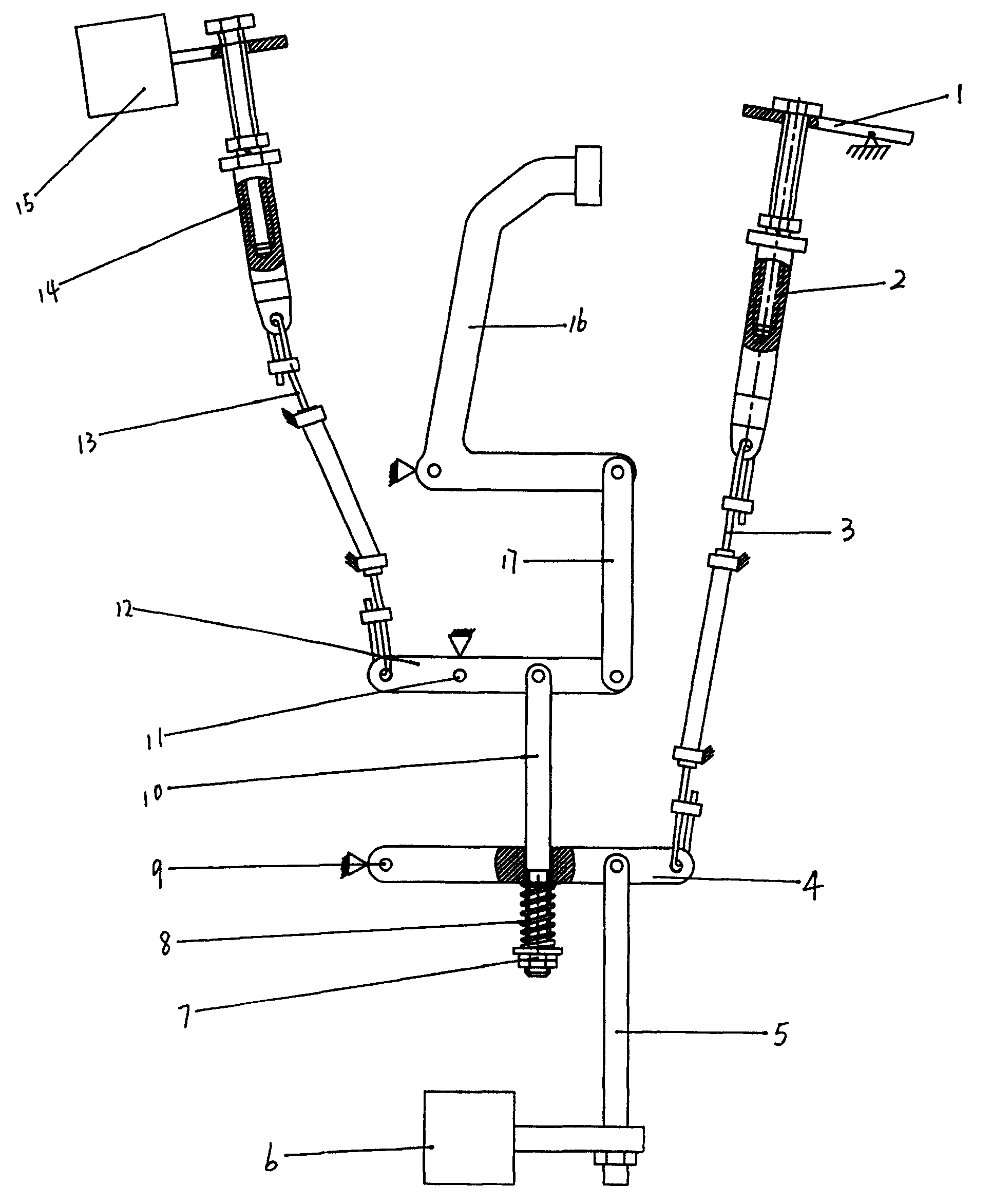
图1是本发明摩托车联动刹车装置第一种实施例的总体结构示意图。Fig. 1 is a schematic diagram of the overall structure of the first embodiment of the motorcycle linkage braking device of the present invention.
图2是本发明摩托车联动刹车装置第二种实施例的总体结构示意图。Fig. 2 is a schematic diagram of the overall structure of the second embodiment of the motorcycle linkage braking device of the present invention.
图3是本发明摩托车联动刹车装置第三种实施例的总体结构示意图。Fig. 3 is a schematic diagram of the general structure of the third embodiment of the motorcycle linkage braking device of the present invention.
附图中:1、手把;2、调距组件;3、后轮车闸钢丝索;4、手动摆杆;5、连接杆;6、后轮车闸;7、调节螺母;8、压缩弹簧;9、转动支点;10、调距拉杆;11、转动支点;12、脚踏摆杆;13、前轮车闸钢丝索;14、调距组件;15、前轮车闸;16、脚踏板;17、拉杆;18、调距杆;19、拉伸弹簧;20、片弹簧或扭簧。In the attached drawings: 1. Handle; 2. Distance adjustment assembly; 3. Rear wheel brake wire rope; 4. Manual swing lever; 5. Connecting rod; 6. Rear wheel brake; 7. Adjusting nut; 8. Compression Spring; 9. Rotation fulcrum; 10. Distance adjustment pull rod; 11. Rotation fulcrum; 12. Pedal swing rod; 13. Front wheel brake wire rope; 14. Distance adjustment component; 15. Front wheel brake; 16. Foot Pedal; 17, pull rod; 18, distance adjustment rod; 19, tension spring; 20, sheet spring or torsion spring.
具体实施方式Detailed ways
如图1所示,本发明摩托车联动刹车装置第一种实施例,包括前轮车闸15、前轮车闸钢丝索13、脚踏摆杆12、拉杆17、脚踏板16、后轮车闸6、连接杆5、手动摆杆4、后轮车闸钢丝索3、手把1,所述脚踏摆杆12设有转动支点11,前轮车闸钢丝索13的一端与前轮车闸15相连,前轮车闸钢丝索13的另一端与脚踏摆杆12的一端相连,脚踏摆杆12的另一端与拉杆17的一端相连,拉杆17的另一端与脚踏板16相连,所述手动摆杆4的一端设有转动支点9,手动摆杆4的另一端与后轮车闸钢丝索3的一端相连,后轮车闸钢丝索3的另一端与手把1相连,连接杆5的一端与后轮车闸6相连,连接杆5的另一端与手动摆杆4的摆动端相连,脚踏摆杆12与手动摆杆4之间设有联动弹性连接件,所述联动弹性连接件包括调距拉杆10、压缩弹簧8(除图1中的压簧外还可以为橡胶弹簧、蝶形弹簧等),调距拉杆10的上端与脚踏摆杆12的拉杆连接端相连,所述手动摆杆4的摆动端设有通孔,调距拉杆10的下端穿过手动摆杆4的通孔并伸出手动摆杆4的下方,调距拉杆10的下端设有外螺纹,压缩弹簧8套在调距拉杆10的下端,由调节螺母7将压缩弹簧8固定在调距拉杆10的下端与手动摆杆4之间,既可实现压缩弹簧8的一端与调距拉杆10下端的连接,又可以方便地调节脚踏联动控制后轮刹车的自由行程,前轮车闸15预留一定的前后轮差动刹车空行程,即脚踏控制前轮刹车的自由行程大于脚踏联动控制后轮刹车的自由行程。为了方便调节刹车自由行程,前轮车闸15与前轮车闸钢丝索13之间可以设有调距组件14,手把1与后轮车闸钢丝索3之间可以设有调距组件2。本发明摩托车联动刹车装置的工作原理是:a、单用手刹:转动手把1使后轮车闸钢丝索3带动手动摆杆4转动,继而带动后轮车闸6刹车;b、单踩脚刹:踩下脚踏板16使拉杆17带动脚踏摆杆12转动,从而拉动调距拉杆10,通过压缩弹簧8迫使手动摆杆4转动,继而带动后轮车闸6先行刹车,而脚踏摆杆12转动的同时拉紧前轮车闸钢丝索13并消除前轮车闸15预留的前后轮差动刹车空行程(此空行程是为保证先刹后轮再刹前轮而预留的),随着脚踏板16继续下行,拉杆17带着脚踏摆杆12继续转动(此时后轮车闸6的刹车效果也随之越来越大)直至拉动前轮车闸15刹车;c、手、脚共同刹车:此过程和作用与单踩脚刹的过程和作用相似,但刹车时间更短。As shown in Figure 1, the first embodiment of the motorcycle linkage braking device of the present invention includes a
如图2所示,本发明摩托车联动刹车装置第二种实施例,所述联动弹性连接件包括调距杆18、拉伸弹簧19,调距杆18的上端设有外螺纹,调距杆18的上端穿过脚踏摆杆12设有的通孔由调节螺母固定,既可实现调距杆18与脚踏摆杆12的连接,又可以方便地调节脚踏联动控制后轮刹车的自由行程,拉伸弹簧19的一端与调距杆18的下端相连接,拉伸弹簧19的另一端与手动摆杆4的摆动端相连接,其余结构同第一种实施例。As shown in Figure 2, the second embodiment of the motorcycle linkage braking device of the present invention, the linkage elastic connector includes a distance adjustment rod 18, a tension spring 19, the upper end of the distance adjustment rod 18 is provided with an external thread, and the distance adjustment rod The upper end of 18 passes through the through hole that the
如图3所示,本发明摩托车联动刹车装置第三种实施例,所述联动弹性连接件为片弹簧20,片弹簧20的一端与脚踏摆杆12的拉杆连接端连接,片弹簧20的另一端位于手动摆杆4的下方并抵住手动摆杆4的摆动端或与手动摆杆4的摆动端稍有空隙,其余结构同第一种实施例。As shown in Figure 3, the third embodiment of the motorcycle linkage braking device of the present invention, the linkage elastic connector is a
本发明摩托车联动刹车装置第四种实施例,所述联动弹性连接件为扭簧20,扭簧20的一端与脚踏摆杆12的拉杆连接端连接,扭簧20的另一端位于手动摆杆4的下方并抵住手动摆杆4的摆动端或与手动摆杆4的摆动端稍有空隙,其余结构同第一种实施例。In the fourth embodiment of the motorcycle interlocking brake device of the present invention, the interlocking elastic connector is a
当然本发明摩托车联动刹车装置还远不止以上几种实施方式,比如在第一种实施例的基础上,调距拉杆10的下端与手动摆杆4的摆动端相连,所述脚踏摆杆12的拉杆连接端设有通孔,调距拉杆10的上端穿过脚踏摆杆12的通孔并伸出脚踏摆杆12的上方,调距拉杆10的上端设有外螺纹,压缩弹簧8套在调距拉杆10的上端,由调节螺母7将压缩弹簧8固定在调距拉杆10的上端与脚踏摆杆12之间,同样能达到目的,因此只要在脚踏摆杆12与手动摆杆4之间设有联动弹性连接件,都应该在本发明的保护范围内。Of course, the motorcycle linkage braking device of the present invention is far more than the above several embodiments. For example, on the basis of the first embodiment, the lower end of the
Claims (4)
Priority Applications (1)
| Application Number | Priority Date | Filing Date | Title |
|---|---|---|---|
| CNB2005100236689A CN100360373C (en) | 2005-01-25 | 2005-01-25 | Motorcycle linkage brake device |
Applications Claiming Priority (1)
| Application Number | Priority Date | Filing Date | Title |
|---|---|---|---|
| CNB2005100236689A CN100360373C (en) | 2005-01-25 | 2005-01-25 | Motorcycle linkage brake device |
Publications (2)
| Publication Number | Publication Date |
|---|---|
| CN1673023A CN1673023A (en) | 2005-09-28 |
| CN100360373C true CN100360373C (en) | 2008-01-09 |
Family
ID=35045858
Family Applications (1)
| Application Number | Title | Priority Date | Filing Date |
|---|---|---|---|
| CNB2005100236689A Expired - Fee Related CN100360373C (en) | 2005-01-25 | 2005-01-25 | Motorcycle linkage brake device |
Country Status (1)
| Country | Link |
|---|---|
| CN (1) | CN100360373C (en) |
Families Citing this family (3)
| Publication number | Priority date | Publication date | Assignee | Title |
|---|---|---|---|---|
| CN102530167B (en) * | 2012-02-22 | 2015-06-24 | 隆鑫通用动力股份有限公司 | Combined brake system for motorcycle and motorcycle thereof |
| CN106585838B (en) * | 2016-11-28 | 2022-10-18 | 重庆宗申机车工业制造有限公司 | Linkage brake device of motorcycle |
| CN109649354A (en) * | 2017-10-11 | 2019-04-19 | 李大明 | Application when braking or emergency braking of " gold partly the claps braking " method in the quick of vehicle, galloping |
Citations (6)
| Publication number | Priority date | Publication date | Assignee | Title |
|---|---|---|---|---|
| CN1243795A (en) * | 1998-07-21 | 2000-02-09 | 本田技研工业株式会社 | Front and rear link braking device for two wheel vehicle |
| JP2001278168A (en) * | 2000-03-31 | 2001-10-10 | Honda Motor Co Ltd | Front and rear wheel brake linkage for vehicles |
| JP2001278169A (en) * | 2000-03-31 | 2001-10-10 | Honda Motor Co Ltd | Front and rear wheel brake linkage for vehicles |
| CN2492457Y (en) * | 2000-10-09 | 2002-05-22 | 刘敬 | Brake mechanism for motor-cycle |
| CN2542548Y (en) * | 2002-04-03 | 2003-04-02 | 夏伟 | Double-coupled brake device of motorcycle |
| CN2778664Y (en) * | 2005-02-02 | 2006-05-10 | 叶忻泉 | Motorcycle braking device |
-
2005
- 2005-01-25 CN CNB2005100236689A patent/CN100360373C/en not_active Expired - Fee Related
Patent Citations (6)
| Publication number | Priority date | Publication date | Assignee | Title |
|---|---|---|---|---|
| CN1243795A (en) * | 1998-07-21 | 2000-02-09 | 本田技研工业株式会社 | Front and rear link braking device for two wheel vehicle |
| JP2001278168A (en) * | 2000-03-31 | 2001-10-10 | Honda Motor Co Ltd | Front and rear wheel brake linkage for vehicles |
| JP2001278169A (en) * | 2000-03-31 | 2001-10-10 | Honda Motor Co Ltd | Front and rear wheel brake linkage for vehicles |
| CN2492457Y (en) * | 2000-10-09 | 2002-05-22 | 刘敬 | Brake mechanism for motor-cycle |
| CN2542548Y (en) * | 2002-04-03 | 2003-04-02 | 夏伟 | Double-coupled brake device of motorcycle |
| CN2778664Y (en) * | 2005-02-02 | 2006-05-10 | 叶忻泉 | Motorcycle braking device |
Also Published As
| Publication number | Publication date |
|---|---|
| CN1673023A (en) | 2005-09-28 |
Similar Documents
| Publication | Publication Date | Title |
|---|---|---|
| CN100360373C (en) | Motorcycle linkage brake device | |
| CN206107474U (en) | Footboard sitting posture tricycle rear wheel braking system | |
| CN207169029U (en) | Swing bassinet structure | |
| CN2105433U (en) | Medium automobile brake controlling mechanism | |
| CN201276107Y (en) | Hand braking maneuver mechanism of tractor | |
| CN201211900Y (en) | Wheeled support of automatic lifting pedal type motorcycle and electric motor vehicle | |
| CN205059915U (en) | Electric vehicle braking device | |
| CN201012159Y (en) | Brake mechanism of walking aid vehicle for old people | |
| CN204056159U (en) | A kind of Kickboard Scooter that simultaneously can carry out service brake and parking brake | |
| CN101214815B (en) | A brake for an industrial vehicle | |
| CN2778664Y (en) | Motorcycle braking device | |
| CN202029834U (en) | Automobile parking brake controlling device | |
| CN214565967U (en) | A tricycle brake mechanism | |
| CN205294538U (en) | Safety tongs aggregate unit | |
| CN209776713U (en) | Foot brake combined brake device for motorcycle | |
| CN2785489Y (en) | Full-mechanical pedal linkage shoes sheath machine | |
| CN115782572A (en) | Brake throttle control device suitable for narrow operation space of automobile for disabled people | |
| CN205931141U (en) | Tricycle brake structure | |
| CN219127124U (en) | Cross type braking device of hand-push wheelchair | |
| CN205930857U (en) | Endless track vehicle turns to and braking operation mechanism | |
| CN209921533U (en) | Novel large-stroke brake handle | |
| CN223059178U (en) | A brake handle | |
| CN2823011Y (en) | Braking device with self-unlocking function | |
| CN201553136U (en) | Wheeled tractor secondary brake control device | |
| CN101032438A (en) | Wheelchair device |
Legal Events
| Date | Code | Title | Description |
|---|---|---|---|
| C06 | Publication | ||
| PB01 | Publication | ||
| C10 | Entry into substantive examination | ||
| SE01 | Entry into force of request for substantive examination | ||
| C14 | Grant of patent or utility model | ||
| GR01 | Patent grant | ||
| ASS | Succession or assignment of patent right |
Owner name: WENZHOU UNIVERSITY Free format text: FORMER OWNER: YE XINQUAN; QIU YIFU Effective date: 20080425 |
|
| C41 | Transfer of patent application or patent right or utility model | ||
| TR01 | Transfer of patent right |
Effective date of registration: 20080425 Address after: Zhejiang province Wenzhou City Chashan Higher Education Park of Wenzhou University 6C503 zip code: 325035 Patentee after: Wenzhou University Address before: Room 104, 14 head of Shuangjing head village, West Road, Wenzhou, Zhejiang, zip code: 325000 Co-patentee before: Qiu Yifu Patentee before: Ye Xin spring |
|
| C17 | Cessation of patent right | ||
| CF01 | Termination of patent right due to non-payment of annual fee |
Granted publication date: 20080109 Termination date: 20110125 |