CN100434331C - Driving device for small four-track mobile robot - Google Patents
Driving device for small four-track mobile robot Download PDFInfo
- Publication number
- CN100434331C CN100434331C CNB2007100631352A CN200710063135A CN100434331C CN 100434331 C CN100434331 C CN 100434331C CN B2007100631352 A CNB2007100631352 A CN B2007100631352A CN 200710063135 A CN200710063135 A CN 200710063135A CN 100434331 C CN100434331 C CN 100434331C
- Authority
- CN
- China
- Prior art keywords
- swing arm
- wheel
- driving
- seat
- driving device
- Prior art date
- Legal status (The legal status is an assumption and is not a legal conclusion. Google has not performed a legal analysis and makes no representation as to the accuracy of the status listed.)
- Expired - Fee Related
Links
Images


Landscapes
- Toys (AREA)
- Manipulator (AREA)
- Motorcycle And Bicycle Frame (AREA)
Abstract
本发明涉及一种能够在崎岖路面或复杂地形条件下机动行驶,具有较高机动性和较强越障力的小型四履带移动机器人驱动装置。该装置由箱体、左右对称布置的行走履带驱动装置、摆臂驱动装置和摆臂履带组件构成。机器人的履带和摆臂均由直流伺服电机直接驱动,省去了复杂的传动机构,摆臂驱动直流伺服电机则安装在从动轮和摆臂轮内部,在保证机器人具有高机动性和强越障力的同时,克服了传统驱动、传动系统零件众多、结构复杂、效率低下的缺点,降低了系统能耗,节省了内部空间,减轻了整体重量,提高了机器人的工作可靠性和行驶稳定性,为小型履带式地面移动机器人驱动装置提供了新的设计方案和新的技术途径。
The invention relates to a driving device of a small four-track mobile robot capable of maneuvering on rough roads or complex terrain conditions, and having relatively high maneuverability and strong obstacle-surmounting force. The device is composed of a box body, a walking track driving device symmetrically arranged left and right, a swing arm driving device and a swing arm track assembly. The track and swing arm of the robot are directly driven by a DC servo motor, which saves the complicated transmission mechanism, and the DC servo motor driven by the swing arm is installed inside the driven wheel and the swing arm wheel, ensuring that the robot has high maneuverability and strong obstacle surmounting At the same time, it overcomes the shortcomings of traditional drive and transmission system with many parts, complex structure and low efficiency, reduces system energy consumption, saves internal space, reduces overall weight, and improves the working reliability and driving stability of the robot. It provides a new design scheme and a new technical approach for the driving device of a small crawler-type ground mobile robot.
Description
技术领域 technical field
本发明属于地面移动机器人技术领域,具体涉及一种能够在崎岖路面或复杂地形条件下机动行驶,具有较高机动性和较强越障力的小型四履带移动机器人驱动装置。The invention belongs to the technical field of ground mobile robots, and in particular relates to a driving device for a small four-track mobile robot capable of maneuvering on rough roads or complex terrain conditions and having high maneuverability and strong obstacle-surpassing force.
背景技术 Background technique
近年来,地面移动机器人已经广泛应用于社会生活的各个领域,具有轻、小、快等优点的小型移动机器人尤其受到人们的青睐。现有小型地面移动机器人通常应用于军事侦察、安全排爆、特殊地域检测等领域,在功能上对机动性和灵活性有较高的要求,而在驱动结构上又追求小型化、简单化、轻量化,如何从设计上协调好功能与结构两者之间的关系,是小型地面移动机器人设计领域的难题。纵观国内外现有小型地面移动机器人驱动装置,广泛采用的是电机加传动系的驱动方式,存在结构复杂、体积庞大、效率低下等缺点,尤其对于四履带移动机器人而言,行走、摆臂两套驱动传动装置会占用机器人宝贵的空间资源,并徒增机器人系统的重量、体积和能耗,限制了其小型化发展。In recent years, ground mobile robots have been widely used in various fields of social life, and small mobile robots with the advantages of lightness, smallness, and speed are especially favored by people. Existing small ground mobile robots are usually used in fields such as military reconnaissance, safe detonation, and special area detection. They have high requirements for mobility and flexibility in terms of functions, and they pursue miniaturization, simplification, and Lightweight, how to coordinate the relationship between function and structure in design is a difficult problem in the field of small ground mobile robot design. Looking at the existing small ground mobile robot drive devices at home and abroad, the drive mode of motor plus drive train is widely used, which has the disadvantages of complex structure, bulky size, and low efficiency. Especially for four-track mobile robots, walking, swinging arms, etc. Two sets of drive transmissions will occupy valuable space resources of the robot, and will only increase the weight, volume and energy consumption of the robot system, limiting its miniaturization development.
发明内容 Contents of the invention
本发明提供一种能够在崎岖路面或复杂地形条件下机动行驶,具有较高机动性和较强越障力的小型四履带移动机器人驱动装置,目的是在保证机器人具有高机动性和强越障力的同时,克服传统驱动、传动系统零件众多、结构复杂、效率低下的缺点,降低系统能耗,节省内部空间,减轻整体重量,提高机器人的工作可靠性和行驶稳定性,为小型履带式地面移动机器人驱动装置提供新的设计方案和新的技术途径。The invention provides a driving device for a small four-track mobile robot that can maneuver on rough roads or complex terrain conditions, and has high maneuverability and strong obstacle-surmounting force. At the same time, it overcomes the shortcomings of traditional drive and transmission system with many parts, complex structure and low efficiency, reduces system energy consumption, saves internal space, reduces overall weight, improves the working reliability and driving stability of the robot, and is a small tracked ground robot. Mobile robot drives offer new design solutions and new technological approaches.
为解决上述技术问题本发明采用的技术方案是:一种小型四履带移动机器人驱动装置,包括箱体,左右对称布置的行走驱动装置、摆臂驱动装置和摆臂组件。其中行走驱动装置位于箱体后部,包括左右对称布置在箱体两侧的主动轮、从动轮、行走履带,主动轮内部套有行走驱动电机,行走驱动电机在驱动主动轮转动的同时起到主动轮轴的作用;行走驱动电机输出端插入主动轮连轴器中,并通过紧定螺钉和键带动连轴器转动,主动轮连轴器通过键连接带动主动轮,主动轮外侧设有弹性挡圈;行走驱动电机通过紧定螺钉固定在移动座中,移动座可以在箱体后部的主动轮轴固定座中前后移动,从而调节主动轮的前后位置,起到张紧调节的作用。摆臂驱动装置包括布置在从动轮外侧同轴的摆臂轮,从动轮通过绕轮轴周向对称布置的四根摆臂轮同步销带动摆臂轮,保证摆臂轮与从动轮转速相同;摆臂轴座贯穿从动轮和摆臂轮中心,并且通过螺钉固定在箱体侧壁上;摆臂轴座中套有摆臂驱动电机,电机输出轴通过摆臂连轴器带动摆臂组件转动。摆臂履带组件包括内臂,外臂,摆臂张紧组件,前段支板,摆臂小轮和摆臂履带,其中内臂套接在从动轮和摆臂轮之间;外臂转动中心与摆臂轮同轴,且与摆臂连轴器固连;摆臂张紧组件连接了内、外臂以及前段支板,对摆臂履带起张紧作用。In order to solve the above technical problems, the technical solution adopted by the present invention is: a small four-crawler mobile robot driving device, including a box body, a walking driving device arranged symmetrically from left to right, a swing arm driving device and a swing arm assembly. The driving device is located at the rear of the box body, including driving wheels, driven wheels, and walking tracks symmetrically arranged on both sides of the box body. The driving wheel is covered with a walking driving motor, which plays a role in driving the driving wheel to rotate. The function of the driving wheel shaft; the output end of the walking drive motor is inserted into the driving wheel coupling, and the coupling is driven to rotate through the set screw and the key. circle; the walking drive motor is fixed in the moving seat through set screws, and the moving seat can move back and forth in the driving wheel shaft fixing seat at the rear of the box, thereby adjusting the front and rear positions of the driving wheel and playing the role of tension adjustment. The swing arm driving device includes a swing arm wheel arranged coaxially outside the driven wheel, and the driven wheel drives the swing arm wheel through four swing arm wheel synchronous pins arranged symmetrically around the wheel axis to ensure that the swing arm wheel and the driven wheel rotate at the same speed; The arm shaft seat runs through the center of the driven wheel and the swing arm wheel, and is fixed on the side wall of the box by screws; the swing arm drive motor is sleeved in the swing arm shaft seat, and the output shaft of the motor drives the swing arm assembly to rotate through the swing arm coupling. The swing arm crawler assembly includes an inner arm, an outer arm, a swing arm tensioning assembly, a front support plate, a swing arm small wheel and a swing arm track, wherein the inner arm is sleeved between the driven wheel and the swing arm wheel; the rotation center of the outer arm is connected to the The swing arm wheel is coaxial and fixedly connected with the swing arm coupling; the swing arm tensioning assembly connects the inner and outer arms and the front support plate, and plays a tensioning role on the swing arm track.
所述行走驱动电机输出轴的外端面与主动轮外侧平齐,最大限度的减少了行走驱动电机在箱体内所占的空间。The outer end surface of the output shaft of the walking driving motor is flush with the outer side of the driving wheel, which minimizes the space occupied by the walking driving motor in the box.
所述摆臂驱动电机完全包含在摆臂轴座中,节省了空间。The driving motor of the swing arm is completely included in the shaft seat of the swing arm, which saves space.
所述移动座通过与移动座盖板固接形成工字滑块,进而嵌入主动轮轴固定座和箱体侧壁形成的导轨中。The moving seat is fixedly connected with the cover plate of the moving seat to form an I-shaped slider, and then embedded in the guide rail formed by the fixed seat of the driving wheel shaft and the side wall of the box.
所述主动轮轴固定座的两端各有一根紧定螺栓,用于限定移动座的位置,进而限定主动轮的张紧位置,实现对行走履带的张紧。There is a set bolt at both ends of the fixed seat of the driving wheel shaft, which is used to limit the position of the moving seat, and then limit the tensioning position of the driving wheel, so as to realize the tensioning of the walking track.
所述从动轮和摆臂轮之间还装有两个隔圈,对装的隔圈固定了摆臂轴承的位置。Two spacer rings are also housed between the driven wheel and the swing arm wheel, and the spacer rings of the pair have fixed the position of the swing arm bearing.
所述摆臂轮同步销贯穿两个隔圈,且其两端分别插入从动轮和摆臂轮中。The synchronizing pin of the swing arm wheel runs through two spacers, and its two ends are respectively inserted into the driven wheel and the swing arm wheel.
所述摆臂张紧组件包括固定在内臂和外臂之间的顶紧座,两根导向轴插入顶紧座中,滑动座插入两根导向轴中,并可沿导向轴移动,滑动座通过紧定螺钉限定其与导向轴的相对位置,两个前段支板固定在滑动座的两端,摆臂小轮安装在前段支板的最前端。The swing arm tensioning assembly includes a tightening seat fixed between the inner arm and the outer arm. Two guide shafts are inserted into the tightening seat. The sliding seat is inserted into the two guiding shafts and can move along the guiding shaft. The sliding seat The relative position between it and the guide shaft is limited by the set screw, the two front section support plates are fixed on the two ends of the sliding seat, and the swing arm small wheel is installed on the front end of the front section support plate.
本发明的有益效果:电机作为主动轮轴,对主动轮起到支撑、定位和驱动的多重作用,简化了传动机构,省去了传统传动方式中的轴承件,减轻了驱动装置的重量;此外,主动轮与摆臂都是由驱动电机直接驱动,省去了烦琐的传动机构,最大限度的节省了空间,降低了系统故障率,为移动机器人进一步小型化、轻量化提供了解决方案。Beneficial effects of the present invention: the motor is used as the driving wheel shaft, which plays multiple functions of supporting, positioning and driving the driving wheel, simplifies the transmission mechanism, saves the bearing parts in the traditional transmission mode, and reduces the weight of the driving device; in addition, Both the drive wheel and the swing arm are directly driven by the drive motor, which saves the cumbersome transmission mechanism, saves space to the greatest extent, reduces the system failure rate, and provides a solution for the further miniaturization and weight reduction of mobile robots.
附图说明 Description of drawings
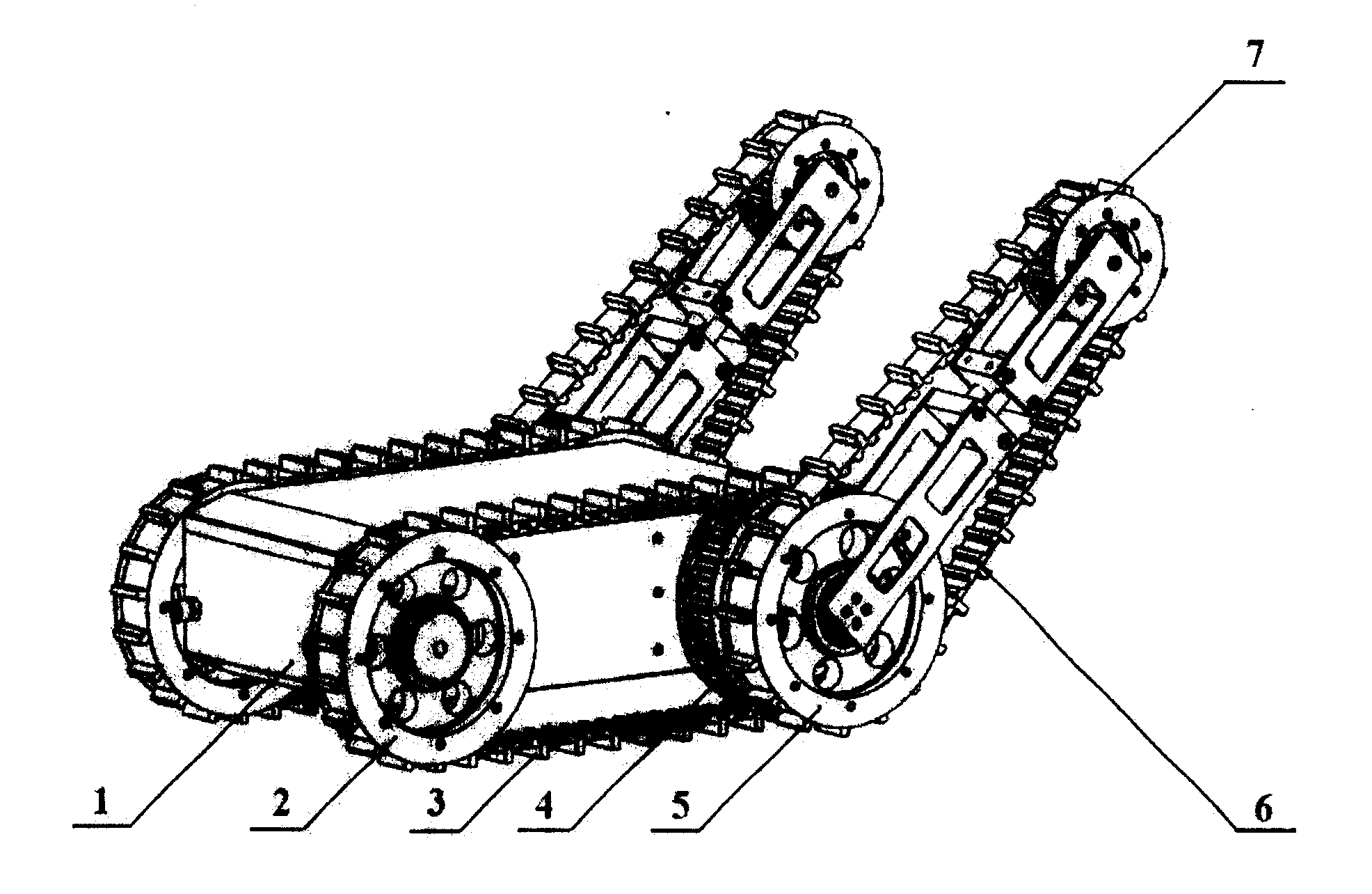
附图1是小型四履带机器人总体结构示意图;Accompanying
附图2(a)是小型四履带机器人行走驱动装置剖视图;附图2(b)是小型四履带机器人行走驱动装置分解示意图;Accompanying drawing 2 (a) is the sectional view of walking driving device of small-sized four-crawler robot; Accompanying drawing 2 (b) is the exploded schematic diagram of walking driving device of small-sized four-crawler robot;
附图3是小型四履带机器人摆臂驱动装置剖视图;Accompanying
附图4是小型四履带机器人摆臂组件结构示意图;Accompanying
附图5是小型四履带机器人俯视图。Accompanying
附图中,1-箱体,2-主动轮,3-行走履带,4-从动轮,5-摆臂轮,6-摆臂履带,7-摆臂小轮,8-弹性挡圈,9-主动轮连轴器,10-紧定螺栓,11-行走驱动电机,12-移动座盖板,13-主动轮轴固定座,14-移动座,15-隔圈,16-摆臂轮同步销,17-摆臂连轴器,18-外臂,19-内臂,20-摆臂轴承,21-摆臂驱动电机,22-摆臂轴座,23-前段支板,24-顶紧座,25-滑动座,26-导向轴。In the accompanying drawings, 1-box, 2-driving wheel, 3-traveling track, 4-driven wheel, 5-swing arm wheel, 6-swing arm track, 7-swing arm small wheel, 8-circlip, 9 -Drive wheel coupling, 10-set bolts, 11-travel drive motor, 12-movable seat cover, 13-drive wheel shaft fixing seat, 14-movable seat, 15-spacer, 16-swing arm wheel synchronous pin , 17-swing arm coupling, 18-outer arm, 19-inner arm, 20-swing arm bearing, 21-swing arm drive motor, 22-swing arm shaft seat, 23-front support plate, 24-top tight seat , 25-sliding seat, 26-guide shaft.
具体实施方式 Detailed ways
下面结合附图对本发明作进一步说明。The present invention will be further described below in conjunction with accompanying drawing.
本发明小型四履带移动机器人驱动装置,包括箱体1、左右对称布置的行走履带驱动装置、摆臂驱动装置和摆臂履带组件。其中行走履带驱动装置位于箱体1后部,包括对称布置在箱体1外部两侧的主动轮2、行走履带3、从动轮4、弹性挡圈8、主动轮连轴器9、调节螺栓10、行走履带驱动电机11、移动座盖板12、主动轮轴固定座13、移动座14和若干标准紧固件。行走履带驱动电机11的前端及输出轴插入主动轮连轴器9的中心通孔中,电机输出轴的外端面与主动轮连轴器9中心通孔的外端面平齐,再通过紧定螺钉和平键实现行走履带驱动电机11和主动轮连轴器9的相对周向和轴向固定;然后将连为一体的行走履带驱动电机11和主动轮连轴器9一同插入主动轮2的中心通孔中,主动轮连轴器9上开有弹性挡圈卡槽,通过弹性挡圈8使主动轮2实现在主动轮连轴器9上的轴向定位,主动轮连轴器9再通过平键连接带动主动轮2,这样当行走履带驱动电机11在通过主动轮连轴器9驱动主动轮2转动时,电机输出轴连同主动轮连轴器9一起就会起到主动轮2的轮轴作用。行走履带驱动电机11通过紧定螺钉固定在移动座14中,移动座14可以在箱体1后部的主动轮轴固定座13中前后移动,以调节主动轮2的前后位置,起到调节行走履带张紧程度的作用。The driving device of the small-sized four-crawler mobile robot of the present invention includes a
摆臂驱动装置包括摆臂轮5、隔圈15、摆臂轮同步销16、摆臂连轴器17、摆臂驱动电机21、摆臂轴座22和若干标准件。摆臂轮5位于从动轮4外侧,且与从动轮4同轴;从动轮4通过绕轮轴周向对称布置的四根摆臂轮同步销16带动摆臂轮5,保证摆臂轮5与从动轮4转速相同;摆臂轴座22通过螺钉固定在箱体1侧壁上,并且贯穿从动轮4和摆臂轮5中心,在从动轮4和摆臂轮5转动时起到轮轴的作用;摆臂驱动电机21的输出轴插入摆臂连轴器17的通孔中,再通过紧定螺钉和平键实现摆臂驱动电机21和摆臂连轴器17的相对周向和轴向固定;然后将连为一体的摆臂驱动电机21和摆臂连轴器17一同插入摆臂轴座22的通孔中,进而通过紧定螺钉固定摆臂驱动电机21在摆臂轴座22中的周向和轴向位置;外臂18通过螺钉固定在摆臂连轴器17外端,从而使摆臂驱动装置可以带动摆臂组件做360°转动。Swing arm driving device comprises
摆臂履带组件包括摆臂履带6、外臂18、内臂19、摆臂轴承20、摆臂张紧组件、前段支板23以及若干标准件。其中内臂19套接在从动轮4和摆臂轮5之间的摆臂轴承20上;外臂18的转动中心与摆臂轮5同轴,且与摆臂连轴器17固连;摆臂张紧组件连接了内臂19、外臂18以及前段支板23,对摆臂履带6起张紧作用。The swing arm track assembly includes the
所述摆臂驱动电机21完全包含在摆臂轴座22中。The swing
所述移动座14通过与移动座盖板12固接形成工字滑块,进而嵌入主动轮轴固定座13和箱体1侧壁形成的导轨中。The moving
所述主动轮轴固定座13的两端各有一根紧定螺栓10,用于限定移动座14的位置,进而限定主动轮2的张紧位置,实现对行走履带3的张紧。The two ends of the fixed
所述从动轮4和摆臂轮5之间还装有两个隔圈15,对装的隔圈15固定了摆臂轴承20的位置。Two
所述摆臂轮同步销16贯穿两个隔圈15,且其两端分别插入从动轮4和摆臂轮5中。The swing arm
所述摆臂张紧组件包括摆臂小轮7、前段支板23、顶紧座24、滑动座25和导向轴26。顶紧座24固定在内臂19和外臂18两者前端之间,两根导向轴26插入顶紧座24中,滑动座25插入两根导向轴26中,并可沿导向轴26移动,滑动座25通过紧定螺钉限定其与导向轴26的相对位置,两个前段支板23固定在滑动座25的两端,摆臂小轮7安装在前段支板23的最前端。The swing arm tensioning assembly includes a swing arm
下面结合附图对本发明工作原理做进一步说明。小型四履带移动机器人驱动装置,如图1所示,机器人整体为左右对称结构,行走驱动装置驱动主动轮2转动,主动轮2带动行走履带3,并将转动传递给箱体前部的从动轮4,实现机器人在地面的行走。同时,从动轮4将转动传递给摆臂轮5,从而带动摆臂履带6转动,实现机器人的攀爬功能。当左右两个驱动装置差动时,可以实现机器人转向。图2所示,行走驱动电机11直接通过主动轮连轴器9驱动主动轮2转动,同时,行走驱动电机11固定在移动座14中,又起到主动轮轴的作用。通过调节主动轮轴固定座13两端的紧定螺栓10可以限定移动座14的位置,从而实现对机器人行走履带3的张紧。图3所示,摆臂驱动电机21固定在摆臂轴座22中,并且通过摆臂连轴器17直接驱动外臂18转动,从而驱动整个摆臂组件转动。从动轮4与摆臂轮5都套在摆臂轴座22外部,其间隔有两个隔圈15,当从动轮转动时,四根摆臂轮同步销16带动摆臂轮5一起转动,保证了摆臂轮5与从动轮4同步转动。图4所示,顶紧座24固定在内臂19和外臂18之间,将二者固连,移动座25可以在固定在顶紧座24上的两根导向轴26上滑动,并通过螺钉锁定位置,从而实现对摆臂履带6的张紧。图5所示机器人驱动装置俯视图,可见本发明最大限度的节省了机器人箱体的内部空间。The working principle of the present invention will be further described below in conjunction with the accompanying drawings. The driving device of a small four-track mobile robot, as shown in Figure 1, has a left-right symmetrical structure as a whole. The driving device drives the
Claims (7)
Priority Applications (1)
| Application Number | Priority Date | Filing Date | Title |
|---|---|---|---|
| CNB2007100631352A CN100434331C (en) | 2007-01-29 | 2007-01-29 | Driving device for small four-track mobile robot |
Applications Claiming Priority (1)
| Application Number | Priority Date | Filing Date | Title |
|---|---|---|---|
| CNB2007100631352A CN100434331C (en) | 2007-01-29 | 2007-01-29 | Driving device for small four-track mobile robot |
Publications (2)
| Publication Number | Publication Date |
|---|---|
| CN101007548A CN101007548A (en) | 2007-08-01 |
| CN100434331C true CN100434331C (en) | 2008-11-19 |
Family
ID=38696276
Family Applications (1)
| Application Number | Title | Priority Date | Filing Date |
|---|---|---|---|
| CNB2007100631352A Expired - Fee Related CN100434331C (en) | 2007-01-29 | 2007-01-29 | Driving device for small four-track mobile robot |
Country Status (1)
| Country | Link |
|---|---|
| CN (1) | CN100434331C (en) |
Cited By (1)
| Publication number | Priority date | Publication date | Assignee | Title |
|---|---|---|---|---|
| CN101890986A (en) * | 2010-06-13 | 2010-11-24 | 上海中为智能机器人有限公司 | Deformable all-terrain adaptable robot walking mechanism |
Families Citing this family (29)
| Publication number | Priority date | Publication date | Assignee | Title |
|---|---|---|---|---|
| CN101363520B (en) * | 2007-08-15 | 2011-05-11 | 深圳市艾立克电子有限公司 | Auto-tensioning drive structure and support head assembly for monitoring equipment |
| CN101428652B (en) * | 2007-11-07 | 2010-06-02 | 中国科学院沈阳自动化研究所 | Movable robot for ice and snow surface |
| CN101446203B (en) * | 2007-11-28 | 2011-09-28 | 上海市电力公司电缆输配电公司 | Method for checking dangerous environment of urban electric network tunnel by robot |
| CN101417674B (en) * | 2008-11-20 | 2010-05-12 | 太原理工大学 | Coal mine underground search and rescue detection robot motion device |
| CN101659053B (en) * | 2009-06-29 | 2011-04-27 | 雷学军 | Robot suitable for cleaning and sterilizing under a plurality of environments |
| CN101723002B (en) * | 2009-11-06 | 2011-06-22 | 北京理工大学 | Elastic bow-shaped vehicle body ground robot |
| CN101734295B (en) * | 2010-02-03 | 2012-03-21 | 中国人民解放军国防科学技术大学 | Deformed caterpillar robot |
| US8157032B2 (en) * | 2010-04-06 | 2012-04-17 | Robotex Inc. | Robotic system and method of use |
| CN102180204B (en) * | 2011-04-27 | 2012-11-28 | 东南大学 | Guide-arm-type front-wheel joint mechanism of mobile robot |
| GB2494444B (en) * | 2011-09-09 | 2013-12-25 | Dyson Technology Ltd | Drive arrangement for a mobile robot |
| CN102358361A (en) * | 2011-09-26 | 2012-02-22 | 吉林大学 | Adaptive multi-road-condition caterpillar composite-driving biomimetic robot |
| CN102582706B (en) * | 2012-02-27 | 2013-05-08 | 太原理工大学 | Coal mine underground search-and-rescue detection robot moving device |
| CN102730093A (en) * | 2012-06-21 | 2012-10-17 | 西安交通大学 | Transmission mechanism of robot |
| CN103231748B (en) * | 2013-04-26 | 2015-05-27 | 哈尔滨工程大学 | Inside and outside reinforced structural type configuration-changeable obstacle crossing robot |
| CN104139810B (en) * | 2013-05-11 | 2017-09-29 | 焦浩 | A kind of robot running gear |
| CN103318288A (en) * | 2013-06-03 | 2013-09-25 | 上海大学 | Synchronous belt driving type full tracked robot |
| CN104875799A (en) * | 2015-05-31 | 2015-09-02 | 南京理工大学 | Small-sized fixed creeper truck with variable front guide wheel angle |
| CN105500364A (en) * | 2016-01-14 | 2016-04-20 | 任曲波 | Hygiene and epidemic prevention monitoring and rescue robot |
| CN107074307A (en) * | 2016-06-07 | 2017-08-18 | 罗春晖 | One kind balance means of transport |
| CN106393050A (en) * | 2016-09-29 | 2017-02-15 | 国网重庆市电力公司电力科学研究院 | Robot suitable for long and narrow tunnel autonomous obstacle avoidance |
| CN106627820A (en) * | 2016-12-19 | 2017-05-10 | 安徽天裕汽车零部件制造有限公司 | Crawler robot swing arm driving device |
| CN106667383A (en) * | 2016-12-30 | 2017-05-17 | 肇庆市小凡人科技有限公司 | Climbing driving device of glass curtain wall cleaning robot |
| CN108202775B (en) * | 2018-03-12 | 2024-02-13 | 湖南中矿金禾机器人研究院有限公司 | Double-drive double-arm concentric four-axis crawler-type mobile platform for small mining robot |
| CN108639169A (en) * | 2018-04-24 | 2018-10-12 | 上海钧工智能技术有限公司 | A kind of overturning arm mechanism of caterpillar robot |
| CN110271617A (en) * | 2019-06-24 | 2019-09-24 | 广西科技大学 | A kind of two-segment type crawler belt climbing robot |
| CN112677721B (en) * | 2020-12-28 | 2022-11-15 | 北京理工大学 | Multi-driving-mode vehicle for complex terrain and obstacle crossing method thereof |
| CN115805998B (en) * | 2021-09-15 | 2025-08-12 | 核动力运行研究所 | Transmission device of irradiation-resistant double-swing-arm crawler-type robot |
| CN114954712B (en) * | 2022-06-02 | 2023-04-11 | 江苏迈吉易威电动科技有限公司 | Wheel hub motor crawler wheel with gait control function |
| CN116159270A (en) * | 2023-02-27 | 2023-05-26 | 江汉大学 | Helium balloon fire-fighting auxiliary equipment |
Citations (4)
| Publication number | Priority date | Publication date | Assignee | Title |
|---|---|---|---|---|
| US4596298A (en) * | 1982-06-26 | 1986-06-24 | Tokyo Shibaura Denki Kabushiki Kaisha | Crawler vehicles |
| CN86106914A (en) * | 1985-10-28 | 1987-04-22 | 沃斯特-阿尔派因股份公司 | The creeper undercarriage that is used for heavy carrier vehicle |
| CN1076655C (en) * | 1999-10-08 | 2001-12-26 | 东华大学 | Autonomous modification four track-foot robot walking mechanism |
| CN1676397A (en) * | 2004-03-31 | 2005-10-05 | 中国科学院沈阳自动化研究所 | Deformable crawler-type traveling mechanism |
-
2007
- 2007-01-29 CN CNB2007100631352A patent/CN100434331C/en not_active Expired - Fee Related
Patent Citations (4)
| Publication number | Priority date | Publication date | Assignee | Title |
|---|---|---|---|---|
| US4596298A (en) * | 1982-06-26 | 1986-06-24 | Tokyo Shibaura Denki Kabushiki Kaisha | Crawler vehicles |
| CN86106914A (en) * | 1985-10-28 | 1987-04-22 | 沃斯特-阿尔派因股份公司 | The creeper undercarriage that is used for heavy carrier vehicle |
| CN1076655C (en) * | 1999-10-08 | 2001-12-26 | 东华大学 | Autonomous modification four track-foot robot walking mechanism |
| CN1676397A (en) * | 2004-03-31 | 2005-10-05 | 中国科学院沈阳自动化研究所 | Deformable crawler-type traveling mechanism |
Cited By (1)
| Publication number | Priority date | Publication date | Assignee | Title |
|---|---|---|---|---|
| CN101890986A (en) * | 2010-06-13 | 2010-11-24 | 上海中为智能机器人有限公司 | Deformable all-terrain adaptable robot walking mechanism |
Also Published As
| Publication number | Publication date |
|---|---|
| CN101007548A (en) | 2007-08-01 |
Similar Documents
| Publication | Publication Date | Title |
|---|---|---|
| CN101007548A (en) | Small-sized four-peddrail mobile robot driving device | |
| CN104443085B (en) | Crawler type six degree of freedom mobile robot | |
| CN103273979A (en) | Splittable snake-like robot with multiple motion modes | |
| CN108748124A (en) | Snake-shaped robot | |
| CN113650691B (en) | All-terrain obstacle-surmounting spherical robot | |
| CN100354171C (en) | Dangerous operation robot with wheel-leg-crawler combined moving mechanism | |
| CN104875798B (en) | Transformer station's wheel carries out compound switchable type mobile robot | |
| CN204488926U (en) | Diagonal angle differential steering four-wheeled | |
| CN104787133B (en) | A kind of upset arm mechanism suitable for wheel-track combined chassis | |
| CN102975782A (en) | Wheel foot amphibious robot mechanism based on differential wheel eccentric mechanism | |
| CN104691611B (en) | Diagonal differential steering four-wheel wagon and control method | |
| CN101797936A (en) | Wheel swinging-type compound drive device for miniature mobile robot | |
| CN102887181B (en) | Swinging arm drive device for tracked robot | |
| CN108791548B (en) | A kind of compound mobile mechanism of two-wheeled-leg-crawler | |
| CN101797888B (en) | Composite movable reconnaissance robot device | |
| CN100396451C (en) | Autonomous flipping crawler robot walking drive device | |
| CN102730093A (en) | Transmission mechanism of robot | |
| CN101758755A (en) | Split wheel for paddle wheel of robot suitable for amphibious ground | |
| CN104648504B (en) | A kind of bionical amphibious robot spring wheel foot crawling device | |
| CN108660871B (en) | Single track switch assembly and track assembly having the same | |
| CN101758741B (en) | All-in-one robot wheel suitable for amphibious ground | |
| CN104442191B (en) | Double; two off-centre operation Variable Eccentricity Stump-jump wheels | |
| CN204278929U (en) | Two eccentric Variable Eccentricity Stump-jump wheel | |
| CN201712688U (en) | Small-sized mobile robot wheel swinging type composite driving device | |
| CN110406604A (en) | Crawler type traveling platform and caterpillar robot |
Legal Events
| Date | Code | Title | Description |
|---|---|---|---|
| C06 | Publication | ||
| PB01 | Publication | ||
| C10 | Entry into substantive examination | ||
| SE01 | Entry into force of request for substantive examination | ||
| C14 | Grant of patent or utility model | ||
| GR01 | Patent grant | ||
| C17 | Cessation of patent right | ||
| CF01 | Termination of patent right due to non-payment of annual fee |
Granted publication date: 20081119 Termination date: 20100129 |