CN86106914A - The creeper undercarriage that is used for heavy carrier vehicle - Google Patents
The creeper undercarriage that is used for heavy carrier vehicle Download PDFInfo
- Publication number
- CN86106914A CN86106914A CN198686106914A CN86106914A CN86106914A CN 86106914 A CN86106914 A CN 86106914A CN 198686106914 A CN198686106914 A CN 198686106914A CN 86106914 A CN86106914 A CN 86106914A CN 86106914 A CN86106914 A CN 86106914A
- Authority
- CN
- China
- Prior art keywords
- supporting
- crawler belt
- triangle
- crawler
- creeper undercarriage
- Prior art date
- Legal status (The legal status is an assumption and is not a legal conclusion. Google has not performed a legal analysis and makes no representation as to the accuracy of the status listed.)
- Pending
Links
- 241000219098 Parthenocissus Species 0.000 title claims abstract description 19
- 230000007246 mechanism Effects 0.000 claims abstract description 10
- 238000006073 displacement reaction Methods 0.000 claims description 5
- 230000005484 gravity Effects 0.000 claims description 5
- 239000011295 pitch Substances 0.000 claims description 3
- 239000004744 fabric Substances 0.000 description 2
- 230000009471 action Effects 0.000 description 1
- 230000008901 benefit Effects 0.000 description 1
- 230000005540 biological transmission Effects 0.000 description 1
- 230000008859 change Effects 0.000 description 1
- 230000002650 habitual effect Effects 0.000 description 1
- 230000006872 improvement Effects 0.000 description 1
Images
Classifications
-
- E—FIXED CONSTRUCTIONS
- E02—HYDRAULIC ENGINEERING; FOUNDATIONS; SOIL SHIFTING
- E02F—DREDGING; SOIL-SHIFTING
- E02F9/00—Component parts of dredgers or soil-shifting machines, not restricted to one of the kinds covered by groups E02F3/00 - E02F7/00
- E02F9/02—Travelling-gear, e.g. associated with slewing gears
- E02F9/024—Travelling-gear, e.g. associated with slewing gears with laterally or vertically adjustable wheels or tracks
Landscapes
- Engineering & Computer Science (AREA)
- Mining & Mineral Resources (AREA)
- Civil Engineering (AREA)
- General Engineering & Computer Science (AREA)
- Structural Engineering (AREA)
- Jib Cranes (AREA)
- Non-Deflectable Wheels, Steering Of Trailers, Or Other Steering (AREA)
- Arrangement Or Mounting Of Propulsion Units For Vehicles (AREA)
- Body Structure For Vehicles (AREA)
- Handcart (AREA)
Abstract
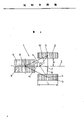
The creeper undercarriage 1 that is used for heavy carrier vehicle as wheeled scraper excavator or wheeled loading machine, has four crawler belts 2,9, Zhang Chengyi supporting triangle 4.Two crawler belts in front 9 are less with the spacing of the traveling gear longitudinal axis 3, are designed to steerable.Be supported on the axis of revolution 11 of the swing type mechanism of supporting on the triangle 4, the direction from the center-of-gravity position 10 of supporting triangle 4 towards supporting triangle forward terminal 8 moves along leg-of-mutton high 7, thereby makes the duty ratio of pressing to crawler belt 2 and 9 balanced.
Description
The present invention relates to a kind of creeper undercarriage that is used to have the heavy carrier vehicle of cantilever turning gear, as wheeled scraper excavator or wheeled loading machine, have four crawler belts at least, wherein the distance of at least two the parallel crawler belts and the vehicle longitudinal axis is greater than other two crawler belts of arranging along the longitudinal direction of car displacement that have at least.This creeper undercarriage that has turning gear carries huge cantilever usually, is that vertical axis of revolution is done rotatable binding with underframe basically around one.Each cantilever is used the weight arm balance mostly, makes need be parallel to the cantilever axis of revolution from the supporting power that traveling gear is obtained and roughly be on the cantilever axis of revolution.
Had the structure of a series of creeper undercarriages to know for people, wherein most crawler belts all are supporting powers on the ground, use this creeper undercarriage, and supporting power is distributed on the bigger area, thereby avoids sinking of traveling gear.The traveling gear of layout parallel to each other, the traveling gear behaviour that has many crawler belts is in addition known on two crawler belt bases.The vehicle that has only two crawler belts, turning to is by one in two crawler belts another to be braked or quicken to realize.The such crawler belt of each bar of multi-track traveling gear can be designed to steerable, and is linked to being can be rotating with respect to supporting structure, and this supporting structure then is connected with creeper undercarriage.When arranging three crawler belts, usually two rear portions that are arranged in traveling gear parallel to each other wherein, and be parallel to the vehicle longitudinal axis, it is steerable that the 3rd crawler belt then is designed to, and tool is arranged in the crawler belt front center position of not handling along longitudinal direction of car.In such structure, the base supports of swing type mechanism is on 3 o'clock, and opening is a supporting triangle.By such base support and axis of revolution that can rotating cantilever, by habitual structural arrangement, generally be to be placed on the leg-of-mutton center of gravity of supporting, from but on the intersection point of the Zhang San of institute dihedral mass axis.
The objective of the invention is, create a kind of the sort of creeper undercarriage of at a first brush just mentioning, it is compared with traditional creeper undercarriage, and the bearing load of allowing is identical, and the length of creeper undercarriage and width are all less.The present invention mainly is that the vertical axis of rotation of cantilever gyration mechanism moves on to the supporting triangle along on the summit of longitudinal direction of car from the supporting triangle core of being opened by each crawler belt for the content that solves this task and propose.Thus, the axis of revolution of swing type mechanism is moved to the supporting vertex of a triangle from the leg-of-mutton center of gravity of the supporting of being opened by each crawler belt, and power transmission just can change common mode of transfer force for each crawler belt, makes all bearing loads equably of each bar crawler belt.The manipulation of vehicle obtains important improvement simultaneously, and the mutual lateral distance of crawler belt can be selected forr a short time, and compares with conventional confguration, still can obtain same big supporting power.The design of preferential this kind of employing, the arrangement pitches that makes two crawler belts that can handle jointly on the longitudinal axis less than other two along the longitudinal direction of car displacement but be parallel to the arrangement pitches of the crawler belt of this longitudinal direction of car, at this moment, this design can help supporting the layout of the axis of revolution of swing type mechanism on the triangle, about 50% supporting power is distributed on the steerable crawler belt, and about 50% supporting power is distributed on two bigger crawler belts of mutual spacing.When in conventional confguration, having three crawler belts, and its every crawler belt all must bear 1/3rd supporting power, and for this purpose axis of revolution is placed on the leg-of-mutton center of gravity of supporting, just can be placed on two crawler belt cloth by additional the 4th crawler belt and to support vertex of a triangle and make it and to turn to, then the point of action of displacing force makes that passing to ground surface force from every crawler belt all equates basically.In all cases, designed according to this invention.Axis of revolution is moved on to the supporting vertex of a triangle, and all designs of the crawler belt number that equals not handle for steerable crawler belt number are all very suitable, and have much advantage.
Below will be by the embodiment that uses plan representation first, the content of creeper undercarriage of the present invention is described further.
On figure, crawler belt 2 after creeper undercarriage 1 significantly has two.Crawler belt 2 is a to the distance of the vehicle longitudinal axis 3 after these two.Active position 5 marks of supporting triangle 4 on the crawler belt 2 of back.On high 7 the connection straight lines 6 of supporting triangle 4 perpendicular to active position 5.By the steerable creeper undercarriage that two crawler belts 9 are formed, cloth is placed on the preceding supporting-point of supporting triangle 4, can turn to around axle 8.Article two, the mutual effective spacing of crawler belt 9 is less than the mutual effective spacing 2a of crawler belt 2, thereby very helps handling these crawler belts.
The center of gravity 10 of supporting triangle 4 is positioned on the intersection point of mass axis.In this case one of mass axis be exactly support leg-of-mutton high by 7.Leg-of-mutton high by 7 along this, the direction miles of relative movement b of the axle of swing type mechanism towards supporting triangular apex 8, and with the new adapter shaft of 11 marks.So, on the vehicle longitudinal axis, and, realized the displacement of swing type mechanism vertical shaft along high 7 the directions that support triangle 4 towards the front fulcrum 8 that can handle crawler belt 9, determine this moment the power that affacts on crawler belt 1 and 9 all to be equated for each bar crawler belt apart from apart from b.Different with the triangular arrangement of conventional confguration, the result who obtains in such a way is that the bearing load that about 50% bearing load is pressed to crawler belt 2,50% then affacts on the steerable crawler belt 9.By such load distribution, stability is improved, and the spacing 2a of the crawler belt 2 that the traveling gear rear portion do not handle can be reduced than traditional design, and is unlikely so causes the loss of bearing value.Simultaneously, the length C of each crawler belt also can shorten with respect to traditional creeper undercarriage, and can not cause the increase of the unit area load of each bar crawler belt 2 or 9 to reach the degree that can not allow.
Claims (4)
1, is used to have the creeper undercarriage 1 of the heavy carrier vehicle of cantilever gyration mechanism, as wheeled scraper excavator or wheeled loading machine, have four crawler belts at least, the crawler belt 9 arranged along the longitudinal direction of car displacement greater than two other at least of the spread length a of at least two parallel crawler belts 2 and the vehicle longitudinal axis 3 wherein, it is characterized in that the vertical axis of rotation 11 of cantilever gyration mechanism moves on to the supporting triangle on the summit 8 of longitudinal direction of car from the center of gravity 10 of the supporting triangle 4 opened by crawler belt 2,9.
2, according to the creeper undercarriage of claim 1, it is characterized in that, the arrangement of two crawler belts that can handle together 9 on the longitudinal axis 3, spacing less than two along longitudinal direction of car displacement but be parallel to the arrangement pitches of the crawler belt 2 of this longitudinal direction of car.
3, according to the creeper undercarriage of claim 1 or 2, it is characterized in that, the layout of the axis of revolution 11 of the swing type mechanism of supporting on the triangle 4 is assigned on the steerable crawler belt 9 about 50% supporting power, and about 50% supporting power then is assigned to each other on two bigger parallel crawler belts 2.
According to the creeper undercarriage of one of claim 1 to 3, it is characterized in that 4, steerable crawler belt 9 equates with the number of the crawler belt of not handling 2.
Applications Claiming Priority (2)
| Application Number | Priority Date | Filing Date | Title |
|---|---|---|---|
| AT3114.85 | 1985-10-28 | ||
| AT0311485A AT384258B (en) | 1985-10-28 | 1985-10-28 | TRACKED CHASSIS FOR HEAVY VEHICLES |
Publications (1)
| Publication Number | Publication Date |
|---|---|
| CN86106914A true CN86106914A (en) | 1987-04-22 |
Family
ID=3545517
Family Applications (1)
| Application Number | Title | Priority Date | Filing Date |
|---|---|---|---|
| CN198686106914A Pending CN86106914A (en) | 1985-10-28 | 1986-10-21 | The creeper undercarriage that is used for heavy carrier vehicle |
Country Status (10)
| Country | Link |
|---|---|
| US (1) | US4729445A (en) |
| CN (1) | CN86106914A (en) |
| AT (1) | AT384258B (en) |
| AU (1) | AU585074B2 (en) |
| CA (1) | CA1270286A (en) |
| DD (1) | DD252406A5 (en) |
| DE (1) | DE3632830A1 (en) |
| HU (1) | HU197860B (en) |
| PL (1) | PL151169B1 (en) |
| YU (1) | YU44595B (en) |
Cited By (1)
| Publication number | Priority date | Publication date | Assignee | Title |
|---|---|---|---|---|
| CN100434331C (en) * | 2007-01-29 | 2008-11-19 | 北京理工大学 | Driving device for small four-track mobile robot |
Families Citing this family (5)
| Publication number | Priority date | Publication date | Assignee | Title |
|---|---|---|---|---|
| DE4415247A1 (en) * | 1994-04-30 | 1995-11-02 | Claas Ohg | Self-propelled harvester, especially combine harvester |
| US6857706B2 (en) * | 2001-12-10 | 2005-02-22 | Placer Dome Technical Services Limited | Mining method for steeply dipping ore bodies |
| US7695071B2 (en) * | 2002-10-15 | 2010-04-13 | Minister Of Natural Resources | Automated excavation machine |
| US7192093B2 (en) * | 2004-04-23 | 2007-03-20 | Placer Dome Technical Services Limited | Excavation apparatus and method |
| CN103057613B (en) * | 2012-12-14 | 2016-03-16 | 大连华锐重工集团股份有限公司 | A kind of side three fulcrum multi-track guiding support device |
Family Cites Families (5)
| Publication number | Priority date | Publication date | Assignee | Title |
|---|---|---|---|---|
| US2375265A (en) * | 1941-02-08 | 1945-05-08 | Wagner Jacob | Airplane |
| US3451494A (en) * | 1967-10-06 | 1969-06-24 | Int Harvester Co | Close-coupled articulated crawler tractor |
| DD129463B1 (en) * | 1976-12-20 | 1980-11-26 | Schmidt Hans Joachim | SUPPORT OF FIRED GROOVE GROUPS OF A TRACKING MACHINE, ESPECIALLY FOR DAY MACHINERY |
| US4174757A (en) * | 1977-10-03 | 1979-11-20 | Caterpillar Tractor Co. | Material ripping vehicle |
| GB2090383B (en) * | 1980-12-26 | 1984-08-30 | Kubota Ltd | Hydrostatic transmission for a tracked vehicle |
-
1985
- 1985-10-28 AT AT0311485A patent/AT384258B/en not_active IP Right Cessation
-
1986
- 1986-09-26 DE DE19863632830 patent/DE3632830A1/en active Granted
- 1986-10-07 YU YU1724/86A patent/YU44595B/en unknown
- 1986-10-09 AU AU63639/86A patent/AU585074B2/en not_active Ceased
- 1986-10-20 HU HU864344A patent/HU197860B/en not_active IP Right Cessation
- 1986-10-21 CN CN198686106914A patent/CN86106914A/en active Pending
- 1986-10-21 CA CA000521037A patent/CA1270286A/en not_active Expired
- 1986-10-23 PL PL1986262004A patent/PL151169B1/en unknown
- 1986-10-27 DD DD86295630A patent/DD252406A5/en not_active IP Right Cessation
- 1986-10-27 US US06/923,644 patent/US4729445A/en not_active Expired - Fee Related
Cited By (1)
| Publication number | Priority date | Publication date | Assignee | Title |
|---|---|---|---|---|
| CN100434331C (en) * | 2007-01-29 | 2008-11-19 | 北京理工大学 | Driving device for small four-track mobile robot |
Also Published As
| Publication number | Publication date |
|---|---|
| DE3632830A1 (en) | 1987-05-07 |
| YU172486A (en) | 1989-04-30 |
| HUT45216A (en) | 1988-06-28 |
| DE3632830C2 (en) | 1991-01-17 |
| YU44595B (en) | 1990-10-31 |
| HU197860B (en) | 1989-06-28 |
| ATA311485A (en) | 1987-03-15 |
| US4729445A (en) | 1988-03-08 |
| PL151169B1 (en) | 1990-08-31 |
| PL262004A1 (en) | 1987-10-05 |
| AU6363986A (en) | 1987-04-30 |
| AU585074B2 (en) | 1989-06-08 |
| DD252406A5 (en) | 1987-12-16 |
| AT384258B (en) | 1987-10-27 |
| CA1270286A (en) | 1990-06-12 |
Similar Documents
| Publication | Publication Date | Title |
|---|---|---|
| CA1075901A (en) | Self-powered toy vehicle chassis and automatically interchangeable bodies | |
| US4009761A (en) | Skid steer vehicle | |
| CN86106914A (en) | The creeper undercarriage that is used for heavy carrier vehicle | |
| DE29814627U1 (en) | Remote controlled toy vehicle with rear wheels with gyro effect | |
| CN109748033A (en) | A kind of logistic storage goods movement device | |
| CA2029274A1 (en) | Automatically shifting stair climber structure for a repositionable hand truck | |
| CN205327110U (en) | Material transfer car(buggy) | |
| US3817555A (en) | Vehicular steering system | |
| CN105620524B (en) | Material transfer vehicle | |
| CN221564570U (en) | Logistics trolley | |
| CN216660097U (en) | Independent suspension driving mechanism | |
| CN223072507U (en) | Heavy vehicle road wheel transfer tool | |
| SE8901432D0 (en) | DEVICE FOR DEVICES | |
| CN216070141U (en) | Construction that practicality is high is with convenient silt car | |
| CN216783594U (en) | Single-row wheel cart for civil engineering land | |
| CN111348012A (en) | Auxiliary brake mechanism of semitrailer | |
| CN207240224U (en) | A kind of chassis walking mechanism and service robot | |
| CN208516880U (en) | A kind of four-wheel drive device applied to fork truck | |
| CN223542431U (en) | Sliding toy | |
| CN219096760U (en) | Trolley is transported to weaving yarn package | |
| EP1247904A3 (en) | Road paver | |
| SU897964A1 (en) | Loader | |
| CN214240333U (en) | Damping device, damping frame and AGV | |
| SE454569B (en) | TOYS, WHICH HAVE A STUFF AND A TIPPABLE LOADER | |
| CN2196590Y (en) | Tipping tricycle |
Legal Events
| Date | Code | Title | Description |
|---|---|---|---|
| C10 | Entry into substantive examination | ||
| SE01 | Entry into force of request for substantive examination | ||
| C06 | Publication | ||
| PB01 | Publication | ||
| RJ01 | Rejection of invention patent application after publication |