CN100558309C - High frequency treatment device - Google Patents
High frequency treatment device Download PDFInfo
- Publication number
- CN100558309C CN100558309C CNB2005800339880A CN200580033988A CN100558309C CN 100558309 C CN100558309 C CN 100558309C CN B2005800339880 A CNB2005800339880 A CN B2005800339880A CN 200580033988 A CN200580033988 A CN 200580033988A CN 100558309 C CN100558309 C CN 100558309C
- Authority
- CN
- China
- Prior art keywords
- electrode
- insulating material
- frequency
- treatment device
- application electrode
- Prior art date
- Legal status (The legal status is an assumption and is not a legal conclusion. Google has not performed a legal analysis and makes no representation as to the accuracy of the status listed.)
- Expired - Fee Related
Links
Images


Classifications
-
- A—HUMAN NECESSITIES
- A61—MEDICAL OR VETERINARY SCIENCE; HYGIENE
- A61B—DIAGNOSIS; SURGERY; IDENTIFICATION
- A61B18/00—Surgical instruments, devices or methods for transferring non-mechanical forms of energy to or from the body
- A61B18/04—Surgical instruments, devices or methods for transferring non-mechanical forms of energy to or from the body by heating
- A61B18/12—Surgical instruments, devices or methods for transferring non-mechanical forms of energy to or from the body by heating by passing a current through the tissue to be heated, e.g. high-frequency current
- A61B18/14—Probes or electrodes therefor
- A61B18/149—Probes or electrodes therefor bow shaped or with rotatable body at cantilever end, e.g. for resectoscopes, or coagulating rollers
-
- A—HUMAN NECESSITIES
- A61—MEDICAL OR VETERINARY SCIENCE; HYGIENE
- A61B—DIAGNOSIS; SURGERY; IDENTIFICATION
- A61B18/00—Surgical instruments, devices or methods for transferring non-mechanical forms of energy to or from the body
- A61B18/04—Surgical instruments, devices or methods for transferring non-mechanical forms of energy to or from the body by heating
- A61B18/12—Surgical instruments, devices or methods for transferring non-mechanical forms of energy to or from the body by heating by passing a current through the tissue to be heated, e.g. high-frequency current
- A61B18/14—Probes or electrodes therefor
- A61B2018/1475—Electrodes retractable in or deployable from a housing
-
- A—HUMAN NECESSITIES
- A61—MEDICAL OR VETERINARY SCIENCE; HYGIENE
- A61B—DIAGNOSIS; SURGERY; IDENTIFICATION
- A61B2218/00—Details of surgical instruments, devices or methods for transferring non-mechanical forms of energy to or from the body
- A61B2218/001—Details of surgical instruments, devices or methods for transferring non-mechanical forms of energy to or from the body having means for irrigation and/or aspiration of substances to and/or from the surgical site
- A61B2218/002—Irrigation
Landscapes
- Health & Medical Sciences (AREA)
- Surgery (AREA)
- Engineering & Computer Science (AREA)
- Life Sciences & Earth Sciences (AREA)
- Biomedical Technology (AREA)
- Otolaryngology (AREA)
- Nuclear Medicine, Radiotherapy & Molecular Imaging (AREA)
- Plasma & Fusion (AREA)
- Physics & Mathematics (AREA)
- Heart & Thoracic Surgery (AREA)
- Medical Informatics (AREA)
- Molecular Biology (AREA)
- Animal Behavior & Ethology (AREA)
- General Health & Medical Sciences (AREA)
- Public Health (AREA)
- Veterinary Medicine (AREA)
- Surgical Instruments (AREA)
Abstract
Description
技术领域 technical field
本发明涉及在灌注液中使用、进行活体组织的切除、气化、电凝等电气手术的高频处置装置。The invention relates to a high-frequency treatment device used in perfusate to perform electrical operations such as excision, gasification, and electrocoagulation of living tissues.
背景技术 Background technique
以往,作为在灌注液中使用的进行活体组织的切除、气化、电凝等电气手术的高频处置装置,使用电切镜(resectoscope)装置。Conventionally, a resectoscope device has been used as a high-frequency treatment device for electrosurgery such as resection, vaporization, and electrocoagulation of living tissue used in a perfusate.
一般,电切镜装置在经由尿道的切除手术、经由颈管的切除手术中使用,在插入体腔内的细长中空套管内主要设有作为观察用内窥镜的光学视管、和活体组织烧灼用的电极单元。Generally, a resectoscope device is used for transurethral resection and transcervical resection, and an optical tube as an observation endoscope and a living tissue cauterization device are mainly provided in a long and thin hollow cannula inserted into a body cavity. The electrode unit used.
在利用电切镜装置进行体腔内部观察时,在套管内经过的液体被输送到体腔内,以确保内窥镜的视野。When using the resectoscope device to observe the inside of the body cavity, the liquid passing through the cannula is delivered into the body cavity to ensure the field of view of the endoscope.
以往,这种被输送到体腔内的液体使用非导电性的D-山梨糖醇溶液等。高频电流从电极经由人体组织被配置于体外的回收电极回收。Conventionally, a non-conductive D-sorbitol solution or the like has been used as the liquid delivered into the body cavity. The high-frequency current is recovered from the electrode via the recovery electrode placed outside the body through human tissue.
其中,在以往的电切镜装置中,由于高频电流刺激神经,有时引起肌肉反射,需要神经阻滞。并且,D-山梨糖醇溶液不能在体腔内长时间输送,这对手术时间带来制约。Among them, in the conventional resectoscope apparatus, since nerves are stimulated by high-frequency currents, muscle reflexes may be caused in some cases, and nerve blocks are required. Moreover, the D-sorbitol solution cannot be transported in the body cavity for a long time, which restricts the operation time.
为了应对这些问题,例如在日本特开2000-201946号公报中公开了以下技术,作为灌注液使用能够在人体的体腔内长时间输送的生理盐水等,并且利用套管取代回收电极来回收高频电流,降低对神经的刺激。In order to deal with these problems, for example, Japanese Patent Application Laid-Open No. 2000-201946 discloses the following technology, which uses physiological saline or the like that can be transported in the body cavity of the human body for a long time as the perfusate, and uses a cannula instead of a recovery electrode to recover high-frequency current, reducing nerve stimulation.
图14是使用生理盐水灌注液的以往的电切镜装置的结构图。Fig. 14 is a configuration diagram of a conventional resectoscope apparatus using physiological saline perfusate.
如图14所示,电切镜装置901构成为具有:电切镜902;生理盐水袋903、输液管904、高频电源905、电极电缆906以及脚踏开关907。As shown in FIG. 14 , the
患者909躺在手术台908上。A
电切镜902的前端部911被插入患者909的尿道等。如图15所示,在前端部911设有电极器914,该电极器914具有前端部形成为大致半圆状的电极912。该电极器914的电极912向着基端侧被管体915覆盖,只露出前端部的形成为大致半圆状的部分。The
返回图14,从生理盐水袋903经由输液管904向电切镜902提供作为灌注液的生理盐水。并且,电切镜902通过电极电缆906与高频电源905连接。Returning to FIG. 14 , physiological saline as a perfusate is supplied to the
通过踩踏脚踏开关907而由高频电源905产生高频电流,经过电极电缆906提供给配置在电切镜902的前端部911前端的电极912。A high-frequency current is generated from a high-
图16是表示向这种电切镜902的前端部911的电极912提供了高频电流时的电极附近的状态的说明图。FIG. 16 is an explanatory diagram showing a state near the electrode when a high-frequency current is supplied to the electrode 912 of the
如图16所示,在从未通电状态开始向前端部的电极912通以高频电流时,由于电极912的电阻而接受到热能的电极912附近的生理盐水被加热,开始产生气泡913。As shown in FIG. 16 , when a high-frequency current is applied to the electrode 912 at the distal end from a non-energized state, the physiological saline near the electrode 912 that receives thermal energy due to the resistance of the electrode 912 is heated, and bubbles 913 begin to be generated.
接着,在向电极912持续通以高频电流时,气泡913的产生量增加,并覆盖整个电极912的周围。此时,电极912与生理盐水之间的电极阻抗急剧上升,由于高压而产生放电。利用通过该放电产生的热量,可以进行组织的切除、气化、电凝等。Next, when the high-frequency current is continuously applied to the electrode 912 , the amount of bubbles 913 generated increases and covers the entire periphery of the electrode 912 . At this time, the electrode impedance between the electrode 912 and the physiological saline rises sharply, and a discharge occurs due to the high voltage. Using the heat generated by this discharge, excision, vaporization, electrocoagulation, and the like of tissue can be performed.
但是,在这种使用生理盐水的现有技术中,为了加热生理盐水以产生气泡,需要较大的功率。因此,存在为了在生理盐水中进行组织的切除、气化、电凝等,需要可以输出大功率的昂贵的高频电源的问题。However, in such a prior art using physiological saline, a large power is required to heat the physiological saline to generate air bubbles. Therefore, there is a problem that an expensive high-frequency power supply capable of outputting large power is required to perform excision, vaporization, electrocoagulation, and the like of tissue in physiological saline.
此外,在输送到患者体内的生理盐水较多时,存在为了产生覆盖整个电极周围所需的气泡而花费时间,进行组织的切除、气化、电凝等的手术时间延长的问题。即,在手术时间延长时,存在患者的负担增大的问题。In addition, when a large amount of physiological saline is delivered to the patient, it takes time to generate the air bubbles required to cover the entire electrode periphery, and there is a problem that surgical procedures such as tissue resection, vaporization, and electrocoagulation are prolonged. That is, when the operation time is prolonged, there is a problem that the burden on the patient increases.
发明内容 Contents of the invention
本发明就是鉴于上述情况而提出的,其目的在于,提供一种高频处置装置,其可以利用更小的功率进行在灌注液(例如生理盐水)中的组织切除、气化、电凝等,而且可以缩短手术时间。The present invention is proposed in view of the above circumstances, and its purpose is to provide a high-frequency treatment device that can perform tissue resection, gasification, electrocoagulation, etc. in perfusion fluid (such as physiological saline) with less power, And can shorten the operation time.
为了达到上述目的,本发明的高频处置装置的特征在于,该高频处置装置具备:产生高频电流的高频发生单元;电极器,其与该高频发生单元电连接,前端具有对所述高频电流进行放电的施加电极,该施加电极的基端侧被第1绝缘材料覆盖;作为来自所述施加电极的所述高频电流的返回侧的插入部,其收纳该电极器并使该电极器可在预定的方向上自由移动;输液单元,其通过该插入部将灌注液输送到所述施加电极附近;以及第2绝缘材料,其由能够自由变更覆盖范围的伸缩材料形成,针对从所述第1绝缘材料的前端露出的所述施加电极的根部部分,该第2绝缘材料从该第1绝缘材料沿着该施加电极、在预定范围内覆盖该施加电极的外表面。In order to achieve the above object, the high-frequency treatment device of the present invention is characterized in that the high-frequency treatment device has: a high-frequency generating unit that generates high-frequency current; The application electrode for discharging the high-frequency current, the base end side of the application electrode is covered with a first insulating material; the insertion part serving as the return side of the high-frequency current from the application electrode accommodates the electrode device and makes The electrode device can move freely in a predetermined direction; the infusion unit, which delivers the perfusate to the vicinity of the application electrode through the insertion part; and the second insulating material, which is formed of a stretchable material that can freely change the coverage, for The root portion of the application electrode exposed from the front end of the first insulating material, and the second insulating material covers the outer surface of the application electrode within a predetermined range along the application electrode from the first insulation material.
根据本发明,可以实现一种高频处置装置,其能够利用更小的功率进行灌注液中的组织切除、气化、电凝等,而且可以缩短手术时间。According to the present invention, a high-frequency treatment device can be realized, which can perform tissue resection, gasification, electrocoagulation, etc. in the perfusate with less power, and can shorten the operation time.
附图说明 Description of drawings
图1是高频处置装置的整体结构图。FIG. 1 is an overall structural diagram of a high-frequency treatment device.
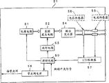
图2是表示高频电源的方框图。Fig. 2 is a block diagram showing a high frequency power supply.
图3是表示电切镜的前端部分的剖面图。Fig. 3 is a cross-sectional view showing the tip portion of the resectoscope.
图4是电极器的结构图。Fig. 4 is a structural diagram of an electrode device.
图5是表示电极器的前端部分的放大图。Fig. 5 is an enlarged view showing the tip portion of the electrode device.
图6是表示高频电源装置的控制流程的流程图。6 is a flowchart showing a control flow of the high-frequency power supply device.
图7是用于说明电切镜的前端部的作用的放大图。Fig. 7 is an enlarged view for explaining the function of the distal end portion of the resectoscope.
图8是用于说明设置在电极器的前端部分的前端电极部的图。FIG. 8 is a diagram for explaining a front-end electrode portion provided at a front-end portion of an electrode device.
图9是用于说明设置在电极器的前端部分的前端电极部的图。FIG. 9 is a diagram for explaining a front-end electrode portion provided at a front-end portion of an electrode device.
图10是用于说明设置在电极器的前端部分的前端电极部的图。FIG. 10 is a diagram for explaining a front-end electrode portion provided at a front-end portion of an electrode device.
图11是用于说明设置在电极器的前端部分的前端电极部的图。FIG. 11 is a diagram for explaining a front-end electrode portion provided at a front-end portion of an electrode device.
图12是用于说明设置在电极器的前端部分的前端电极部的图。FIG. 12 is a diagram for explaining a front-end electrode portion provided at a front-end portion of an electrode device.
图13是用于说明设置在电极器的前端部分的前端电极部的图。FIG. 13 is a diagram for explaining a front-end electrode portion provided at a front-end portion of an electrode device.
图14是包括使用生理盐水灌注液的以往的电切镜的高频处置装置的结构图。FIG. 14 is a configuration diagram of a high-frequency treatment apparatus including a conventional resectoscope using a physiological saline perfusate.
图15是表示以往的电极的图。FIG. 15 is a diagram showing a conventional electrode.
图16是表示以往的电切镜的电极附近的状态的说明图。FIG. 16 is an explanatory view showing a state near electrodes of a conventional resectoscope.
具体实施方式 Detailed ways
以下,参照图1~图7说明本发明的实施方式。Hereinafter, an embodiment of the present invention will be described with reference to FIGS. 1 to 7 .
图1~图7涉及本发明的第一实施方式,图1是高频处置装置的整体结构图,图2是表示高频电源的方框图,图3是表示电切镜的前端部分的剖面图,图4是电极器的结构图,图5是表示电极器的前端部分的放大图,图6是表示高频电源装置的控制流程的流程图,图7是用于说明电切镜的前端部的作用的放大图。1 to 7 relate to a first embodiment of the present invention. FIG. 1 is an overall configuration diagram of a high-frequency treatment device, FIG. 2 is a block diagram showing a high-frequency power supply, and FIG. 3 is a cross-sectional view showing a front end portion of a resectoscope, 4 is a structural diagram of the electrode device, FIG. 5 is an enlarged view showing the front end of the electrode device, FIG. 6 is a flow chart showing the control flow of the high-frequency power supply device, and FIG. 7 is a diagram for explaining the front end of the resectoscope. Enlarged view of the effect.
如图1所示,作为高频处置装置的电切镜1主要由以下部分构成:细管状的套管2;设于该套管2的后端的操作部3;从该操作部3插入套管2内进行观察的光学视管4;作为高频发生单元的高频电源装置21;和电极器5,其被通以来自该高频电源装置21的高频电流,对活体组织进行处置。As shown in Figure 1, a
套管2被从尿道、阴道等插入被检体内部。该套管2包括具有前端部6a的导电性插入部6,和设于该插入部6的后端的主体部7。在该主体部7上设有送水口8和阀门9,该送水口8用于通过插入部6内部向体腔内输送灌注液,在本实施方式中是输送生理盐水。送水口8可以自由拆装地与输液管12连接,该输液管12用于提供装在容器10内的生理盐水11。The cannula 2 is inserted into the subject from the urethra, vagina, or the like. The bushing 2 includes a
另一方面,操作部3具有:可以在套管2的主体部7后端自由拆装地构成的操作部主体14;在该操作部主体14的后端突出设置的导向轴15;可自由滑动地保持在该导向轴15上的滑块16。On the other hand, the operating part 3 has: an operating part main body 14 that can be freely assembled and disassembled at the rear end of the
在导向轴15的后端设有挡块17。在该挡块17和操作部主体14之间,滑块16沿着导向轴15自由往复滑动。并且,导向轴15形成为内部中空的结构。光学视管4插在导向轴15内而插入到套管2中,并且可以自由拆装地连接固定在挡块17上。A stopper 17 is provided at the rear end of the guide shaft 15 . Between this stopper 17 and the operation part main body 14 , the slider 16 is free to reciprocate and slide along the guide shaft 15 . Furthermore, the guide shaft 15 is formed to have a hollow structure inside. The optical tube 4 is inserted into the sleeve 2 through the guide shaft 15 , and is connected and fixed on the block 17 in a detachable manner.
在滑块16上设有保持电极器5的保持部18,并且设有用于向电极器5通以高频电流的通电部19。该通电部19与设在滑块16上的连接器20电导通,设置在高频电源装置21的输出电缆22前端的输出插头23可自由拆装地连接固定在连接器20上。The slider 16 is provided with a holding part 18 for holding the
在该高频电源装置21上连接有具有切换踏板的脚踏开关40,该切换踏板用于进行对电极器5提供高频电流的操作、以及控制高频输出。另外,从高频电源装置21的前面延伸出一端与其连接的信号电缆42,该信号电缆42的另一端与用于连接容器10和输液管12的管夹阀(pitchvalve)41连接。即,管夹阀41通过信号电缆42从高频电源装置21接受电源供给。A foot switch 40 having a switching pedal for supplying a high-frequency current to the
由这些容器10、输液管12和管夹阀41构成输液单元。An infusion unit is constituted by these
并且,在挡块17上设有环状放置部24,以便使用者放置手的拇指。另一方面,在滑块16上设有杆状放置部25,以便使用者放置手的食指、中指和无名指或放置食指到小指,这些放置部24和放置部25被弹性关节26向箭头H方向施力并连接着。Moreover, an annular placing portion 24 is provided on the block 17 for the user to place the thumb of the hand. On the other hand, a rod-shaped placing part 25 is provided on the slider 16 so that the user places the index finger, middle finger and ring finger of the hand or places the index finger to the little finger. Force and connect.
并且,当操作这些放置部24、25,滑块16沿着导向轴15向操作部主体14方向(前方向)滑动时,电极器5的前端电极部27从套管2的前端突出。反之,在向挡块方向(后方向)操作滑块16时,电极器5的前端电极部27被收纳在套管2的前端部6a中。And, when these placement parts 24 and 25 are operated and the slider 16 slides toward the operation part main body 14 (forward direction) along the guide shaft 15, the front
光学视管4包括插入套管2内的插入部28、设在该插入部28的后端的目视部29。在该目视部29的附近设有光导连接器33,在其上可以自由拆装地连接固定着与光源装置30连接的光导缆线31的连接器32。The optical viewing tube 4 includes an insertion portion 28 inserted into the sleeve 2 , and a viewing portion 29 provided at the rear end of the insertion portion 28 . A light guide connector 33 is provided near the viewing portion 29, and a connector 32 of the light guide cable 31 connected to the light source device 30 is detachably connected and fixed thereto.
从光源装置30输出的照明光通过光导电缆31传送到光导连接器33,再通过内置于插入部28中的光导束传送到插入部前端35并射出。The illumination light output from the light source device 30 is transmitted to the light guide connector 33 through the light guide cable 31 , and then transmitted to the front end 35 of the insertion part through the light guide bundle built in the insertion part 28 and emitted.
如图2所示,作为高频发生单元的高频电源装置21构成为具有:控制电路50;电源电路51;高频发生电路52;波形电路53;输出变压器54;电流传感器55;电压传感器56;A/D转换器57和管夹阀电源58。As shown in Figure 2, the high-frequency
电源电路51输出直流电流。高频发生电路52把来自电源电路51的直流电流转换为高频电流。波形电路53根据控制电路50的控制,对高频发生电路52指示高频电流的波形。The power supply circuit 51 outputs a direct current. The high-
输出变压器54将来自高频发生电路52的高频电流输出给与电切镜1连接的输出电缆22内的配线。电流传感器55检测从输出变压器54输出的输出电流。The
电压传感器56检测从输出变压器54输出的输出电压。A/D转换器57把电流传感器55和电压传感器56的信号转换为数字信号。控制电路50根据来自A/D转换器57的数字化后的数据和来自脚踏开关40的信号,控制电源电路51和波形电路53。另外,控制电路50也进行向管夹阀41提供电源的管夹阀电源58的控制。The
下面,使用图3~图5说明从电切镜1的套管2的前端部6a突出并且收纳在前端部6a内的电极器5。Next, the
如图3所示,从电切镜1的前端部6a露出作为电极器5的功能部的前端电极部27。前端电极部27在从侧方观察时弯曲成大致L状,以便容易与组织抵接。如前面所述,通过操作放置部24、25(参照图1)而对电极器5进行自由滑动操作,以使具有前端电极部27的前端部分从电切镜1的前端部6a向前方突出,或者基本上收纳到前端部6a内。As shown in FIG. 3 , a
如图4所示,电极器5的前方侧分支为两部分,并设有作为施加电极的、形成为大致环状(闭环)的金属线即前端电极部27,其分别连接这两个分支端。另外,在电极器5的分支端的前端部分设有由第1(电)绝缘材料构成的护套38。As shown in FIG. 4, the front side of the
在该前端电极部27上,在从电极器5的分支部分到基端侧的中途部分,插通光学视管4的插入部28的引导筒5a固定连接在面向图4的纸面观察时的上方。由此,电极器5在被滑动操作时,由插入了光学视管4的插入部28的引导筒5a引导着行进。On the front
如图4和图5所示,从护套38的前端向面向纸面观察时的下方侧、即垂直方向侧延伸的两个绝缘材料(本实施方式中的第2绝缘材料)37,在预定范围内覆盖前端电极部27。具体地讲,在从设于电极器5的分支端的两个前端部分延伸出来的各个根部部分,前端电极部27分别在预定范围内被绝缘材料37覆盖着。即,两个绝缘材料37分别只在预定范围内,覆盖从在活体组织的切除、气化、电凝等时使用频度较少的、从护套38前端露出的前端电极部27的根部部分。As shown in FIGS. 4 and 5 , the two insulating materials (second insulating materials in this embodiment) 37 extending from the front end of the
该电极器5设有护套38和绝缘材料37,以使金属线的前端电极部27成为与体腔的处置区域接触的接触部,其他的金属线部分成为不接触所述处置区域的非接触部。并且,电极器5中被护套38覆盖的部分成为第1部分,在与该第1部分的轴向不同的方向上延伸的、根部部分为弯曲部的前端电极部27成为第2部分。绝缘材料37覆盖该前端电极部27的根部部分的弯曲部。The
下面,使用图6和图7说明如上所述构成的本实施方式的电切镜的动作。Next, the operation of the resectoscope of this embodiment configured as described above will be described with reference to FIGS. 6 and 7 .
首先,例如从尿道、阴道等将电切镜1插入患者的体腔内。First, the
如图6所示,踩踏、接通脚踏开关40的开关踏板(S1),控制电路50控制管夹阀电源58,向管夹阀41提供电源,暂时停止通过输液管12输送生理盐水(S2)。然后,控制电路50控制高频发生电路52,开始提供高频输出(S3)。As shown in Figure 6, step on and connect the switch pedal (S1) of the foot switch 40, the
此时,由于生理盐水的输送停止,所以在前端电极部27的附近积存被高频电流加热的生理盐水,容易产生气泡。而且,通过暂时停止输送生理盐水,所产生的气泡不会在输液时飞散。并且,如图7所示,提供给前端电极部27的高频电流从作为施加侧的前端电极部27接触活体组织的部分流向作为返回侧的插入部6。由此,接触前端电极部27的组织被实施切除、气化和电凝等。At this time, since the delivery of the physiological saline is stopped, the physiological saline heated by the high-frequency current is accumulated near the
并且,前端电极部27的根部部分被绝缘材料37覆盖,所以前端电极部27与生理盐水接触的表面积小于以往的电极912(参照图15),可以更加有效地进行生理盐水的升温。因此,在露出的前端电极部27的周围容易产生气泡。Moreover, the root portion of the
然后,在步骤S4中,控制电路50通过A/D转换器57取入电流传感器55的电流值,接着在步骤S5中通过A/D转换器57取入电压传感器56的电压值。Then, in step S4 , the
然后,控制电路50在电路内部将所取入的电压值除以电流值,由此计算前端电极部27和作为外套管的插入部6之间的电阻值Z。Then, the
接着,控制电路50进行计算出的电阻值Z是否小于例如500Ω的判定(S7)。控制电路50在计算出的电阻值Z小于500Ω时,返回步骤S4重复相同的处理。Next, the
另一方面,如果计算出的电阻值Z大于500Ω,则整个前端电极部27的周围被气泡包围着,已经产生放电,所以不需要停止生理盐水的输送。然后,控制电路50停止向管夹阀41提供电源(S8),再次开始向前端电极部27附近输送生理盐水。On the other hand, if the calculated resistance value Z is greater than 500Ω, the entire periphery of the
接着,在脚踏开关40的开关踏板被松开时(S9),控制电路50控制高频发生电路52,停止高频输出(S10)。Next, when the switch pedal of the foot switch 40 is released (S9), the
即,根据以上说明,在脚踏开关40的开关踏板接通时,从前端电极部27产生气泡。但是,在脚踏开关40的开关踏板刚被接通后,由于生理盐水的温度上升需要时间,所以在前端电极部27处不怎么产生气泡。此时,处于组织电阻的电阻值Z小于500Ω的状态,控制电路50向管夹阀41提供电源,停止通过输液管12向前端电极部27的附近输送生理盐水。That is, as described above, when the switch pedal of the foot switch 40 is turned on, air bubbles are generated from the
在接通脚踏开关40的开关踏板后经过一定时间时,附着在前端电极部27上的气泡增多,电阻值Z上升。在该电阻值Z达到500Ω时,整个前端电极部27的周围被气泡包围着,处于已产生放电的状态,断开对管夹阀41的电源供给,再次开始通过输液管12向前端电极部27的附近输送生理盐水。When a certain time elapses after the switch pedal of the foot switch 40 is turned on, the number of air bubbles adhering to the
与图14~图16示出的以往的电切镜装置901具有的电极912相比,本实施方式的前端电极部27由于覆盖了绝缘材料37,与生理盐水接触的表面积形成较小的面积,所以能够缩短生理盐水的升温需要的时间。即,本实施方式的电切镜1构成为可以缩短从接通脚踏开关40的开关踏板后,到产生覆盖整个前端电极部27周围的气泡的时间。Compared with the electrode 912 included in the
按照以上所述构成的本实施方式的电切镜1,可以缩短从高频电源装置21开始输出时起,到通过前端电极部27和插入部6产生放电所需要的使整个前端电极部27的周围被气泡覆盖的时间。即,前端电极部27通过绝缘材料37缩小了与生理盐水接触的面积,所以能够缩短前端电极部27附近的生理盐水的液温上升所需要的时间。According to the
因此,本实施方式的电切镜1通过缩短从高频电源装置21输出高频电流的时间,可以获得省电效果,并且容易产生覆盖整个前端电极部27周围的气泡。Therefore, in the
另外,前端电极部27附近的气泡不会由于输液而飞散,所以能够以较小的功率利用气泡覆盖整个前端电极部27使其放电,可以进行活体组织的切除、气化、电凝等。In addition, the air bubbles near the
结果,可以使用小功率的高频电源装置21,可以降低作为高频处置装置的电切镜1的制造成本,并且省电。As a result, a low-power high-frequency
另外,前端电极部27为了与以往的电极912(参照图15)相比缩小与生理盐水的接触面积,在进行切除、气化、电凝等时,可以代替覆盖使用频度较少的、从护套38的前端露出的前端电极部27的根部部分的绝缘材料37,而构成为图8~图13所示的结构。In addition, in order to reduce the contact area with the physiological saline compared with the conventional electrode 912 (refer to FIG. 15 ), the front
如图8所示,对于前端电极部27的从护套38前端露出的根部部分(弯曲部)的外表面,在预定范围中施加作为非导电性膜的第2绝缘材料的绝缘涂层27a。由此,前端电极部27缩小了与生理盐水的接触面积。As shown in FIG. 8 , an insulating
如图9所示,前端电极部27使护套38的作为第2绝缘材料的前端部分沿着延伸方向延伸出来,在预定范围内覆盖根部部分(弯曲部)的外表面。由此,前端电极部27缩小与生理盐水之间的接触面积。在图9中,护套38的前端部分在从侧方观察时形成向下方即垂直方向弯曲的大致L状。As shown in FIG. 9 , the
如图10所示,在前端电极部27上设有由绝缘材料构成的蛇皮形状的蛇管38a(本实施方式中的第2绝缘材料),从而可以自由变更从护套38前端露出的根部部分(弯曲部)的外表面中所期望的覆盖范围。由此,医生等使用者可以在所期望的范围内减小前端电极部27与生理盐水之间的接触面积。As shown in FIG. 10, a serpentine-shaped
根据以上说明的图8~图10所示的前端电极部27的结构,可以抑制生理盐水的升温所需要的时间,容易在前端电极部27的周围产生气泡。并且,由于前端电极部27的外表面露出的面积较小,所以能够通过较少的气泡产生从前端电极部27到插入部6的放电。According to the structure of the
另外,根据图10所示的前端电极部27的结构,医生等使用者可以根据要治疗的患部的情况,适当选择使前端电极部27露出的范围。In addition, according to the structure of the
图11所示的前端电极部27形成为使使用频度最高的环状中央部27c的外径小于从护套38前端露出的根部部分的外径。该中央部27c的外径变细,所以中央部27c与生理盐水之间的接触面积减小。因此,覆盖中央部27c周围的气泡的量少量即可。The
图12所示的前端电极部27利用与图11所示的前端电极部27相同的原理,在面向前方侧的一面上具有多个缺口部27b。缺口部27b与生理盐水之间的接触面积减小。因此,覆盖缺口部27b周围的气泡的量少量即可。The
另外,如图13所示,前端电极部27是描画出环形(闭环)的板状,在前方侧具有多个缺口部27B,也能够获得相同的效果。另外,对该板状的前端电极部27的根部部分施加作为第2绝缘材料的上述绝缘涂层27a。In addition, as shown in FIG. 13 , the front
以上所述的本实施方式的电切镜1的前端电极部27在少量的气泡产生量下接触组织时,其与插入部6之间有效地产生放电,所以能够减少高频电源装置21的功耗,可以实现所使用的高频功率的小功率化。因此,不需要使用可以输出大功率的昂贵的高频电源装置21,可以使用在前端电极部27与组织接触时能够以小功率输出、在短时间内对插入部6进行放电的、价格低廉的高频电源装置21。When the distal
此外,根据本实施方式的电切镜1,可以缩短放电所需要的时间,可以抑制手术时间,也能够减轻患者的负担。In addition, according to the
另外,本发明不限于以上叙述的实施方式,可以在不脱离本发明宗旨的范围内进行各种变形实施。In addition, the present invention is not limited to the embodiments described above, and various modifications can be made without departing from the gist of the present invention.
Claims (7)
Applications Claiming Priority (2)
| Application Number | Priority Date | Filing Date | Title |
|---|---|---|---|
| JP292955/2004 | 2004-10-05 | ||
| JP2004292955 | 2004-10-05 |
Publications (2)
| Publication Number | Publication Date |
|---|---|
| CN101035478A CN101035478A (en) | 2007-09-12 |
| CN100558309C true CN100558309C (en) | 2009-11-11 |
Family
ID=36142718
Family Applications (1)
| Application Number | Title | Priority Date | Filing Date |
|---|---|---|---|
| CNB2005800339880A Expired - Fee Related CN100558309C (en) | 2004-10-05 | 2005-10-05 | High frequency treatment device |
Country Status (5)
| Country | Link |
|---|---|
| US (1) | US7867229B2 (en) |
| EP (1) | EP1797837A4 (en) |
| JP (1) | JP4675329B2 (en) |
| CN (1) | CN100558309C (en) |
| WO (1) | WO2006038646A1 (en) |
Families Citing this family (14)
| Publication number | Priority date | Publication date | Assignee | Title |
|---|---|---|---|---|
| US20080275444A1 (en) * | 2007-05-02 | 2008-11-06 | Olympus Medical Systems Corp. | Endoscopic treatment instrument and tissue incision method |
| GB2492325B (en) * | 2011-06-23 | 2016-06-22 | Gyrus Medical Ltd | Electrosurgical electrode |
| CN102846375B (en) * | 2012-08-16 | 2016-02-03 | 珠海市司迈科技有限公司 | Resectoscope bipolar electrode |
| CN104546119A (en) * | 2015-01-05 | 2015-04-29 | 张建国 | Mucous membrane detacher |
| CN104921804B (en) * | 2015-06-24 | 2018-02-06 | 珠海市司迈科技有限公司 | Left and right shunt circuit bipolar electrode |
| USD861163S1 (en) * | 2017-08-04 | 2019-09-24 | Olympus Winter & Ibe Gmbh | Part of medical instrument |
| US11648047B2 (en) | 2017-10-06 | 2023-05-16 | Vive Scientific, Llc | System and method to treat obstructive sleep apnea |
| DE102018113835A1 (en) * | 2018-06-11 | 2019-12-12 | Olympus Winter & Ibe Gmbh | Assembly aid for attaching electrodes in a resectoscope |
| JP7189971B2 (en) * | 2019-01-28 | 2022-12-14 | オリンパス株式会社 | Electrode unit and endoscope system |
| JP7216191B2 (en) * | 2019-03-29 | 2023-01-31 | オリンパス株式会社 | Electrode unit and resectoscope device |
| WO2021181552A1 (en) * | 2020-03-11 | 2021-09-16 | オリンパス株式会社 | Electrode unit and electrode unit operation method |
| DE102020108614A1 (en) | 2020-03-27 | 2021-09-30 | Olympus Winter & Ibe Gmbh | Electrosurgery generator, electrosurgical system and method for operating an electrosurgery generator |
| DE102022129542A1 (en) * | 2022-11-08 | 2024-05-08 | Olympus Winter & Ibe Gmbh | Electrode for an electrosurgical hand instrument and method for producing an electrode |
| DE102023108868A1 (en) | 2023-04-06 | 2024-10-10 | Bowa-Electronic Gmbh & Co. Kg | Electrode unit for an electrosurgical instrument and electrosurgical instrument |
Citations (5)
| Publication number | Priority date | Publication date | Assignee | Title |
|---|---|---|---|---|
| US3939839A (en) * | 1974-06-26 | 1976-02-24 | American Cystoscope Makers, Inc. | Resectoscope and electrode therefor |
| US5902272A (en) * | 1992-01-07 | 1999-05-11 | Arthrocare Corporation | Planar ablation probe and method for electrosurgical cutting and ablation |
| JP2000201946A (en) * | 1999-01-14 | 2000-07-25 | Olympus Optical Co Ltd | Resectoscope device |
| US6494881B1 (en) * | 1997-09-30 | 2002-12-17 | Scimed Life Systems, Inc. | Apparatus and method for electrode-surgical tissue removal having a selectively insulated electrode |
| US20040019351A1 (en) * | 2002-04-15 | 2004-01-29 | Olympus Optical Co., Ltd. | Resectoscope apparatus and electric operation apparatus |
Family Cites Families (12)
| Publication number | Priority date | Publication date | Assignee | Title |
|---|---|---|---|---|
| DE3603758A1 (en) * | 1985-02-09 | 1986-08-14 | Olympus Optical Co., Ltd., Tokio/Tokyo | RESECTOSCOPE DEVICE |
| US5080660A (en) * | 1990-05-11 | 1992-01-14 | Applied Urology, Inc. | Electrosurgical electrode |
| US5683366A (en) * | 1992-01-07 | 1997-11-04 | Arthrocare Corporation | System and method for electrosurgical tissue canalization |
| US5569244A (en) * | 1995-04-20 | 1996-10-29 | Symbiosis Corporation | Loop electrodes for electrocautery probes for use with a resectoscope |
| JPH09262244A (en) * | 1996-01-24 | 1997-10-07 | Olympus Optical Co Ltd | Resectoscope |
| US5749870A (en) * | 1996-08-23 | 1998-05-12 | Nebl, Inc. | Electrode for coagulation and resection |
| US5919190A (en) * | 1996-12-20 | 1999-07-06 | Vandusseldorp; Gregg A. | Cutting loop for an electrocautery probe |
| JP3782622B2 (en) * | 1999-09-30 | 2006-06-07 | オリンパス株式会社 | Reject electrode |
| JP3791911B2 (en) * | 2002-04-15 | 2006-06-28 | オリンパス株式会社 | Receptoscope device |
| US6918907B2 (en) * | 2003-03-13 | 2005-07-19 | Boston Scientific Scimed, Inc. | Surface electrode multiple mode operation |
| US6939348B2 (en) * | 2003-03-27 | 2005-09-06 | Cierra, Inc. | Energy based devices and methods for treatment of patent foramen ovale |
| US7662151B2 (en) * | 2006-02-15 | 2010-02-16 | Boston Scientific Scimed, Inc. | Contact sensitive probes |
-
2005
- 2005-10-05 WO PCT/JP2005/018422 patent/WO2006038646A1/en not_active Ceased
- 2005-10-05 JP JP2006539312A patent/JP4675329B2/en not_active Expired - Fee Related
- 2005-10-05 EP EP05790546A patent/EP1797837A4/en not_active Withdrawn
- 2005-10-05 CN CNB2005800339880A patent/CN100558309C/en not_active Expired - Fee Related
-
2006
- 2006-11-17 US US11/601,183 patent/US7867229B2/en not_active Expired - Fee Related
Patent Citations (5)
| Publication number | Priority date | Publication date | Assignee | Title |
|---|---|---|---|---|
| US3939839A (en) * | 1974-06-26 | 1976-02-24 | American Cystoscope Makers, Inc. | Resectoscope and electrode therefor |
| US5902272A (en) * | 1992-01-07 | 1999-05-11 | Arthrocare Corporation | Planar ablation probe and method for electrosurgical cutting and ablation |
| US6494881B1 (en) * | 1997-09-30 | 2002-12-17 | Scimed Life Systems, Inc. | Apparatus and method for electrode-surgical tissue removal having a selectively insulated electrode |
| JP2000201946A (en) * | 1999-01-14 | 2000-07-25 | Olympus Optical Co Ltd | Resectoscope device |
| US20040019351A1 (en) * | 2002-04-15 | 2004-01-29 | Olympus Optical Co., Ltd. | Resectoscope apparatus and electric operation apparatus |
Also Published As
| Publication number | Publication date |
|---|---|
| EP1797837A4 (en) | 2008-11-26 |
| CN101035478A (en) | 2007-09-12 |
| JP4675329B2 (en) | 2011-04-20 |
| EP1797837A1 (en) | 2007-06-20 |
| US20070066976A1 (en) | 2007-03-22 |
| US7867229B2 (en) | 2011-01-11 |
| JPWO2006038646A1 (en) | 2008-05-15 |
| WO2006038646A1 (en) | 2006-04-13 |
Similar Documents
| Publication | Publication Date | Title |
|---|---|---|
| CN100558309C (en) | High frequency treatment device | |
| JP4031118B2 (en) | Electrosurgical instrument and method of using the instrument | |
| US4943290A (en) | Electrolyte purging electrode tip | |
| CN108472073A (en) | Electrosurgery unit with multiple monopolar electrode components | |
| JPH10510745A (en) | System and method for electrosurgical resection and ablation | |
| EP0959787A1 (en) | Under water treatment | |
| US7682359B2 (en) | High-frequency treatment apparatus | |
| JP3802698B2 (en) | Receptoscope device | |
| CN100558310C (en) | High-frequency treatment device | |
| JP3791911B2 (en) | Receptoscope device | |
| WO2003105707A1 (en) | Resectoscope | |
| JP3938707B2 (en) | Electrosurgical equipment | |
| JP3978058B2 (en) | Electrosurgical equipment | |
| JP7667748B2 (en) | Electrosurgical instruments, electrosurgical electrodes, and methods for making electrodes for electrosurgical instruments | |
| CN213606844U (en) | Electrode working assembly and bipolar operation electrode device thereof | |
| JP3837082B2 (en) | Receptoscope device | |
| JP2004188023A (en) | Resectoscope apparatus | |
| JP4429522B2 (en) | Receptoscope device | |
| JP3996786B2 (en) | Electrosurgical equipment | |
| JP2002177297A (en) | Resectoscope | |
| JP2024172605A (en) | Electrode Unit | |
| RU101911U1 (en) | ELECTROSURGICAL INSTRUMENT FOR COBLATION | |
| JPS62127046A (en) | Prostate release device of rejectoscope apparatus | |
| JP2003299671A (en) | Resectoscope device | |
| JPH0380847A (en) | Patient electrode for high frequency treatment |
Legal Events
| Date | Code | Title | Description |
|---|---|---|---|
| C06 | Publication | ||
| PB01 | Publication | ||
| C10 | Entry into substantive examination | ||
| SE01 | Entry into force of request for substantive examination | ||
| C14 | Grant of patent or utility model | ||
| GR01 | Patent grant | ||
| CF01 | Termination of patent right due to non-payment of annual fee | ||
| CF01 | Termination of patent right due to non-payment of annual fee |
Granted publication date: 20091111 |