CN101687201A - Waste shredder comprising at least two rotors - Google Patents
Waste shredder comprising at least two rotors Download PDFInfo
- Publication number
- CN101687201A CN101687201A CN200880019237A CN200880019237A CN101687201A CN 101687201 A CN101687201 A CN 101687201A CN 200880019237 A CN200880019237 A CN 200880019237A CN 200880019237 A CN200880019237 A CN 200880019237A CN 101687201 A CN101687201 A CN 101687201A
- Authority
- CN
- China
- Prior art keywords
- rotor
- funnel
- waste shredder
- rotors
- waste
- Prior art date
- Legal status (The legal status is an assumption and is not a legal conclusion. Google has not performed a legal analysis and makes no representation as to the accuracy of the status listed.)
- Granted
Links
Images


Classifications
-
- B—PERFORMING OPERATIONS; TRANSPORTING
- B02—CRUSHING, PULVERISING, OR DISINTEGRATING; PREPARATORY TREATMENT OF GRAIN FOR MILLING
- B02C—CRUSHING, PULVERISING, OR DISINTEGRATING IN GENERAL; MILLING GRAIN
- B02C18/00—Disintegrating by knives or other cutting or tearing members which chop material into fragments
- B02C18/06—Disintegrating by knives or other cutting or tearing members which chop material into fragments with rotating knives
- B02C18/16—Details
- B02C18/22—Feed or discharge means
- B02C18/2225—Feed means
- B02C18/2291—Feed chute arrangements
-
- B—PERFORMING OPERATIONS; TRANSPORTING
- B02—CRUSHING, PULVERISING, OR DISINTEGRATING; PREPARATORY TREATMENT OF GRAIN FOR MILLING
- B02C—CRUSHING, PULVERISING, OR DISINTEGRATING IN GENERAL; MILLING GRAIN
- B02C18/00—Disintegrating by knives or other cutting or tearing members which chop material into fragments
- B02C18/06—Disintegrating by knives or other cutting or tearing members which chop material into fragments with rotating knives
- B02C18/14—Disintegrating by knives or other cutting or tearing members which chop material into fragments with rotating knives within horizontal containers
- B02C18/142—Disintegrating by knives or other cutting or tearing members which chop material into fragments with rotating knives within horizontal containers with two or more inter-engaging rotatable cutter assemblies
Landscapes
- Engineering & Computer Science (AREA)
- Food Science & Technology (AREA)
- Crushing And Pulverization Processes (AREA)
- Crushing And Grinding (AREA)
- Materials For Medical Uses (AREA)
- Detergent Compositions (AREA)
Abstract
Description
技术领域 technical field
本发明涉及一种用于废品(如垃圾、工业废品、可回收材料等)的破碎机,其包括:The present invention relates to a shredder for waste products (such as garbage, industrial waste, recyclable materials, etc.), comprising:
-带有加料室的支撑构件;- support members with feeding chambers;
-两个或多个承载工具转子,其设置在位于加料室的底壁上形成的座上;- two or more carrying tool rotors arranged on seats formed on the bottom wall of the charging chamber;
-可移动的漏斗,其在加料室上滑动并进行往复平移移动,该漏斗具有两端壁并且承载位于转子之间的空间中的多个坚硬的叶片:两端壁和坚硬的叶片向下突出,直至它们触碰到加料室的底部,将要破碎的材料压入转子。- a movable funnel that slides on the charging chamber and performs a reciprocating translational movement, the funnel has two end walls and carries a plurality of rigid blades located in the space between the rotors: the two end walls and the rigid blades protrude downwards , until they touch the bottom of the feeding chamber, pressing the material to be crushed into the rotor.
转子沿与漏斗的平移移动相反的方向转动,并当漏斗移动的平移方向反向时使其转动方向反向,即当漏斗在一方向上平移时(如:从左至右),转子在一方向上转动(如逆时针),反之亦然。The rotor rotates in the opposite direction to the translational movement of the funnel, and when the translational direction of the funnel movement is reversed, its rotation direction is reversed, that is, when the funnel is translated in one direction (for example: from left to right), the rotor is in one direction Turn (eg counterclockwise) and vice versa.
背景技术 Background technique
在对垃圾进行处理时-特别是城市垃圾(固体城市垃圾等)-变得更加重要和必要的是(或至少是合理的),在适当的挑选和分离不易燃或其它易处理的部分之后,对垃圾进行破碎的过程以使剩下材料的平均尺寸足够小,以便用于焚化炉或水泥厂锅炉的可选择的燃料。事实上,向炉子供给的便利性和均化的可能性构成对燃烧热量循环进行正确和有利的操作的必要因素。When dealing with waste - especially municipal waste (solid municipal waste, etc.) - it becomes even more important and necessary (or at least reasonable) that, after proper selection and separation of non-combustible or otherwise easily disposed parts, The process of shredding waste so that the average size of the remaining material is small enough to be used as an alternative fuel for an incinerator or cement plant boiler. In fact, the convenience of supply to the furnace and the possibility of homogenization constitute the necessary factors for a correct and favorable operation of the combustion heat cycle.
此外,对于在经济上可行的垃圾处理来说,该系统的产量,尤其是破碎部分的产量,有必要确保每小时很高的速率,通常为许多吨/小时的指令。Furthermore, for an economically viable waste treatment, the throughput of the system, especially of the shredding fraction, must ensure a very high rate per hour, usually orders of many tons per hour.
通常情况下,使用具有较大或非常大的单个转子的机器可以得到现有的这些产量,所述转子可进行仅一个方向的旋转和工作,并且能产生较大的安装能量和较高的投资费用。Typically, these capacities are available using machines with large or very large single rotors that can rotate and work in only one direction, and that result in greater installed energy and higher investment cost.
然而,该类型的机器具有这样的局限性,当必须进行修理或维护时(由于完成工作的类型,该操作通常是很频繁的),因为必须使整个破碎生产线通常都是不可忽略的阶段不能进行生产操作,因而每个操作从经济角度和实践方面来说都是昂贵的。However, this type of machine has such limitations that when repairs or maintenance have to be carried out (which is usually very frequent due to the type of work being done), since it is necessary to make the entire crushing line, usually a non-negligible stage, cannot be carried out production operations, each of which is therefore expensive both economically and practically.
特别地,为了确保必要的高生产率,现有的机器包括一个具有大的直径和长度的转子,该转子具有很大的惯性转矩并因此可被坚硬物轻易地破坏,未破碎的外来物质(在垃圾中容易出现)与转子的切削边缘相接合,迫使转子立刻停止并使切削工具频繁地被破坏或损坏。In particular, in order to ensure the necessary high productivity, existing machines include a rotor with a large diameter and length, which has a large moment of inertia and can therefore be easily broken by hard, unbroken foreign matter ( prone to debris) engages the cutting edge of the rotor, forcing the rotor to stop immediately and causing the cutting tool to be frequently broken or damaged.
在很多情况下,为了避免操作受到不可接受的打断,一个备用机且用于替换需要被修理或维护的机器,但在很大程度上增加了最初的投资费用。In many cases, in order to avoid unacceptable interruption of operations, a spare machine is used to replace the machine that needs to be repaired or maintained, but greatly increases the initial investment cost.
因此,需要生产一种具有这样特性的用于破碎垃圾的机器,其能进行简单的操作并且廉价,以允许该机器的停机时间和成本得到彻底的减少,而不再需要备用机。Therefore, there is a need to produce a machine for shredding waste with such characteristics that it is simple to operate and inexpensive to allow the downtime and costs of the machine to be drastically reduced without the need for a backup machine.
发明内容 Contents of the invention
本发明中的机器设计为替代现有技术中的机器,其由单个的破碎单元组成(包括转子和相关的对刃),所述破碎单元具有单一的切割方向和很高的产量-因此具有较大或者非常大的尺寸和功率-具有非常易于操作的多转子机器,该多转子机器由多个非常小的具有两个切割方向的破碎单元组成。The machine of the present invention is designed to replace the machines of the prior art and consists of a single crushing unit (including the rotor and associated counter-blades) with a single cutting direction and a very high output - thus a relatively high Large or very large size and power - with a very easy to handle multi-rotor machine consisting of several very small crushing units with two cutting directions.
本发明的目的是提供一种废品破碎机,其包括至少两个转子,以用于克服现有的破碎机存在的问题;该目的通过权利要求1中所描述的特征所限定的废品破碎机实现。The object of the present invention is to provide a waste shredder comprising at least two rotors for overcoming the problems of existing shredders; this object is achieved by a waste shredder defined by the features described in
本发明的进一步的有利特征在从属权利要求中限定。Further advantageous features of the invention are defined in the dependent claims.
附图说明 Description of drawings
本发明以下将参照附图中单纯作为例子示出的(并因此是非限制性的)实施例进行阐述,其中:The invention will be elucidated below with reference to the embodiments shown purely by way of example (and therefore non-limiting) in the accompanying drawings, in which:
附图1示出了根据本发明制造的废品破碎机的透视图,其包括三个转子,以及在其中间位置的漏斗;Accompanying
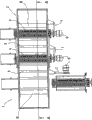
附图2示出了附图1中的破碎机的顶视图;Accompanying
附图3示出了附图1中的破碎机的透视图,在其平移移动的一端处具有漏斗;Figure 3 shows a perspective view of the crusher of Figure 1 with a funnel at one end of its translational movement;
附图4示出了附图3中的破碎机沿附图1中的截面A-A的横截面;Accompanying
附图5示出了附图1中的破碎机的透视图,在其平移移动的另一端部具有漏斗;Figure 5 shows a perspective view of the crusher of Figure 1 with a funnel at the other end of its translational movement;
附图6示出了附图5中的破碎机沿附图1中的截面A-A的横截面;Accompanying
附图7示出了附图1中的破碎机的透视图,其中一个转子与相应的发动机分开,并从加料室中移走;Figure 7 shows a perspective view of the crusher of Figure 1, with one rotor detached from the corresponding motor and removed from the charging chamber;
附图8示出了附图7中的破碎机的顶视图。Figure 8 shows a top view of the crusher of Figure 7 .
在附图中,相应的元件采用相同的附图标记进行表示。In the figures, corresponding elements are indicated with the same reference numerals.
具体实施方式 Detailed ways
附图1中示出了根据本申请制造的废品破碎机1的透视图,其包括三个转子4,漏斗2位于中间位置,其按照箭头F1的方向进行平移移动。The accompanying
废品破碎机1包括支撑承载加料室3的支撑构件12,三个位于加料室3的底壁上形成的座中的转子4,以及一个可移动的漏斗2,其在加料室3上滑动,并进行往复的平移移动,漏斗2还具有两个端壁B、B’并承载多个放置在转子4之间的空间中的坚硬的叶片5:漏斗2的端壁B、B’和叶片5向下突出直至触碰到加料室3的底部,将要被破碎的材料8压入(附图1中未示出)转子4,如上所述,该转子在与漏斗2的平移移动相反的方向上转动(附图3-6)。The
将要被破碎的材料8被转子4的齿夹住并且临近转子4抵抗对刃进行切割(以已知的方式),为了简化附图,在附图中省略了。The
如上所述,当漏斗2的平移方向反向时,转子4的旋转方向也反向。As mentioned above, when the direction of translation of the
而且,在附图1中可以看出驱动转子4的发动机6,每个发动机6被支撑构件7承载并通过其它已知的快速联接/分离装置的凸缘与转子4的轴向接合。Furthermore, in Figure 1 there can be seen the
用于驱动转子4的液压发动机6的优点在于:由于液压发动机适用于频繁的改变用于操作破碎机1所需转动的方向,并且解决了(如过热)而在相同的操作条件下由电力发动机驱动破碎机1的缺陷。The advantage of the
在描述的实施例中,废品破碎机1包括三个转子4和两个与可移动的漏斗2整体形成的叶片5,但是,在不超出本发明的范围的情况下,该废品破碎机1可包括四个转子4和三个叶片5,五个转子和四个叶片5等,破碎机1一般可包括n个转子4和n-1个叶片5,n是大于等于2的整数。In the described embodiment, the
附图2示意地从上面示出了附图1中的破碎机1;附图2中包括加料室3,可移动的漏斗2,端壁B、B’,叶片5和转子4,转子4与发动机6相联并由支撑装置7承载。Accompanying drawing 2 schematically shows
破碎机1的操作将参照附图3-6进行阐述。The operation of the
附图3示意地示出了附图1中的破碎机1的透视图,其具有漏斗2,漏斗2在附图3中沿着箭头F的方向进行平移移动,并到达其平移移动的一端。Accompanying figure 3 schematically shows a perspective view of the
如先前所述,漏斗2进行往复的平移移动,从而使其从附图3中所示的位置到达附图5中所示的位置,反之亦然。As previously mentioned, the
参照附图3和4(附图4示意地示出了沿附图1中的截面A-A截取的附图3中的破碎机1),当漏斗2(其承载叶片5)在箭头F的方向上移动时,叶片5(其在相同的方向上移动,如附图4)和漏斗2的端壁B将要被破碎的材料8压入转子4,转子4在与漏斗2的平移移动相反的方向上转动,以夹住材料8并抵抗对刃切割材料8。Referring to accompanying
转子4在附图3和4中的箭头F的方向上转动。The
通常,破碎机1通过传送带10被供给:漏斗2的往复移动在加料室3的整个表面上分布材料8,允许破碎单元11的平衡操作(附图7),包括至少一个转子4和相应的对刃。Typically, the
在附图4和6中,由每个破碎单元11破碎的材料8通过设置在破碎单元11下面的传送带9移走:在不超出本申请范围的情况下,传送带9可被省略。In figures 4 and 6, the
当漏斗2结束其在箭头F(附图3和4)的方向上的移动时,它的移动方向被反向,同时,转子4的转动方向也被反向:叶片5和漏斗2的与端壁B相对的端壁B’仍然将要被破碎的材料8压入转子4(附图6),转子4仍在与漏斗2的平移方向相反的方向上转动,以夹住材料8并抵抗对刃切割材料8。When the
附图5和6(附图6示意地示出了附图5中的破碎机1沿附图1中的截面A-A截取)示出了附图1中的具有漏斗2的破碎机1,漏斗2通过沿箭头F1的方向移动,到达其平移移动的另一端。Accompanying
在附图5和6中示出了沿箭头F1’转动的转子。The rotor rotating along arrow F1' is shown in Figures 5 and 6 .
附图7示意地示出了附图1中的破碎机1的透视图,其具有破碎单元11,其中一个所述破碎单元与相应的发动机6分离,并沿侧面从加料室3中取出以进行简单快速的替换,而不会迫使整个破碎机1被长时间的停止使用。Accompanying drawing 7 schematically shows a perspective view of the
事实上,将转子4与发动机6分离,以将发动机6带至“铰链联接”位置的装置7转动,从而将所述单元11的锁定装置(本身已知)移开进行修理或维护,使其从加料室3中滑出,由另一单元11替代它,通过锁定装置将其锁定,以便将发动机6与转子4联接并使破碎机1重新投入使用。In fact, the
附图8示意地示出了附图7中的破碎机1的顶视图;从附图8中可看到包括,漏斗2、端壁B、B’、叶片5和从加料室3中移走的单元11,通过装置7带到“铰链联接”位置的相应的发动机6,以及其他单元11,其他单元11的相应转子4与发动机6相联。Accompanying drawing 8 schematically shows the top view of
本领域技术人员可知并且已经由申请人通过实验的方法得以证明,在产量相同的情况下,用本发明的机器取代现有技术中包括单个转子(具有单一的转动方向)的机器是有利的,其中本发明的机器包括两个或多个具有较小单元功率的转子(具有两个转动方向),因为:It is known to those skilled in the art and has been proved by the applicant through experiments that, under the same output conditions, it is advantageous to replace the prior art machines comprising a single rotor (with a single direction of rotation) with the machine of the present invention, Wherein the machine of the invention comprises two or more rotors (with two directions of rotation) with smaller unit power, because:
-需要的产量通过不同破碎单元的产量的总和得到,而所述破碎单元由于其尺寸的限制,使转子的直径减小以及惯性转矩被限制,并且例如由于硬的,未被破碎的外来物质从而需要更大的抵抗突然停机的能力,而没有对单个切削刃和/或转子的轴带来损坏;- the required output is obtained by summing the output of the different crushing units due to their dimensions, the reduced diameter of the rotor and the limited moment of inertia, and e.g. due to hard, unbroken foreign matter There is thus a need for greater resistance to sudden stops without damage to the individual cutting edges and/or the shaft of the rotor;
-通过漏斗2的往复移动的供给以及转子的反向转动的操作,从而消除了在单转子机器中正常存在的停机时间;- the supply by the reciprocating movement of the
-可互换的模块单元11的存在允许任何被破坏的或在任何情况下需要维护的模块单元11在很短的时间内被替换,而只消耗很少的材料和用去很短的停机时间;- the presence of interchangeable
-备用的模块单元11的使用需要很小的投资,并且由以上所述的从技术和经济角度的优点中得到充分回报。- The use of spare
在不脱离本发明保护范围的情况下,本领域技术人员可通过常规的实验和/或技术的进步对本发明中前面所述的破碎机进行修改和改进。Without departing from the protection scope of the present invention, those skilled in the art can modify and improve the crusher described above in the present invention through routine experiments and/or technical progress.
Claims (7)
Applications Claiming Priority (3)
| Application Number | Priority Date | Filing Date | Title |
|---|---|---|---|
| IT001165A ITMI20071165A1 (en) | 2007-06-08 | 2007-06-08 | SHREDDER SHAPE INCLUDING AT LEAST TWO ROTORS |
| ITMI2007A001165 | 2007-06-08 | ||
| PCT/EP2008/001666 WO2008148434A1 (en) | 2007-06-08 | 2008-03-03 | Waste shredder comprising at least two rotors |
Publications (2)
| Publication Number | Publication Date |
|---|---|
| CN101687201A true CN101687201A (en) | 2010-03-31 |
| CN101687201B CN101687201B (en) | 2011-04-20 |
Family
ID=39563367
Family Applications (1)
| Application Number | Title | Priority Date | Filing Date |
|---|---|---|---|
| CN2008800192377A Expired - Fee Related CN101687201B (en) | 2007-06-08 | 2008-03-03 | Waste shredder comprising at least two rotors |
Country Status (8)
| Country | Link |
|---|---|
| US (1) | US7905437B2 (en) |
| EP (1) | EP2152425B1 (en) |
| CN (1) | CN101687201B (en) |
| AT (1) | ATE504356T1 (en) |
| DE (1) | DE602008006065D1 (en) |
| ES (1) | ES2360685T3 (en) |
| IT (1) | ITMI20071165A1 (en) |
| WO (1) | WO2008148434A1 (en) |
Cited By (2)
| Publication number | Priority date | Publication date | Assignee | Title |
|---|---|---|---|---|
| CN105597896A (en) * | 2015-12-24 | 2016-05-25 | 首钢总公司 | Ore grinding and storage system |
| CN106111248A (en) * | 2016-06-28 | 2016-11-16 | 柏伟伟 | Rubbish pulverizes processing means |
Families Citing this family (5)
| Publication number | Priority date | Publication date | Assignee | Title |
|---|---|---|---|---|
| PL2857103T3 (en) * | 2013-10-04 | 2019-07-31 | Lindner, Manuel | Comminuting device |
| PL3248687T3 (en) * | 2016-05-23 | 2020-03-31 | Manuel Lindner | Two-shaft shredder having quick change device |
| US10947453B2 (en) * | 2016-07-12 | 2021-03-16 | Genus Industries, Llc | Method and apparatus for preparing coir |
| PT3446786T (en) * | 2017-08-23 | 2020-01-22 | Untha Shredding Tech Gmbh | Shredding device for shredding material |
| CN112452471B (en) * | 2020-11-10 | 2022-09-27 | 湖南玉和园食品有限公司 | Automatic food processing machinery's crushing mechanism |
Family Cites Families (8)
| Publication number | Priority date | Publication date | Assignee | Title |
|---|---|---|---|---|
| GB1454288A (en) * | 1973-11-07 | 1976-11-03 | Metal Box Co Ltd | Shredding machines |
| US4412659A (en) * | 1981-01-30 | 1983-11-01 | Thermoguard Insulation Co. | Shredding mill |
| US4844363A (en) * | 1987-07-06 | 1989-07-04 | Shredding Systems, Inc. | Hopper ram for shredder |
| US5417375A (en) * | 1994-02-22 | 1995-05-23 | Peterson Pacific Corporation | Material reducing machine |
| US6405949B1 (en) * | 1998-10-28 | 2002-06-18 | Stephen B. Maguire | Shuttle granulator |
| US6773545B2 (en) * | 2000-12-26 | 2004-08-10 | Kimberly-Clark Worldwide, Inc. | Method of forming and metering fluff pulp |
| ITMI20021673A1 (en) * | 2002-07-26 | 2004-01-26 | Satrind Srl | TWO-SHAFT INDUSTRIAL SHREDDER |
| WO2005072877A1 (en) * | 2004-01-30 | 2005-08-11 | Mmd Design & Consultancy Limited | Rotating mineral breaker |
-
2007
- 2007-06-08 IT IT001165A patent/ITMI20071165A1/en unknown
-
2008
- 2008-03-03 DE DE602008006065T patent/DE602008006065D1/en active Active
- 2008-03-03 AT AT08716186T patent/ATE504356T1/en not_active IP Right Cessation
- 2008-03-03 WO PCT/EP2008/001666 patent/WO2008148434A1/en not_active Ceased
- 2008-03-03 US US12/663,548 patent/US7905437B2/en not_active Expired - Fee Related
- 2008-03-03 CN CN2008800192377A patent/CN101687201B/en not_active Expired - Fee Related
- 2008-03-03 EP EP08716186A patent/EP2152425B1/en not_active Not-in-force
- 2008-03-03 ES ES08716186T patent/ES2360685T3/en active Active
Cited By (3)
| Publication number | Priority date | Publication date | Assignee | Title |
|---|---|---|---|---|
| CN105597896A (en) * | 2015-12-24 | 2016-05-25 | 首钢总公司 | Ore grinding and storage system |
| CN105597896B (en) * | 2015-12-24 | 2018-03-06 | 首钢总公司 | A kind of ore crushes stocking system |
| CN106111248A (en) * | 2016-06-28 | 2016-11-16 | 柏伟伟 | Rubbish pulverizes processing means |
Also Published As
| Publication number | Publication date |
|---|---|
| WO2008148434A1 (en) | 2008-12-11 |
| EP2152425B1 (en) | 2011-04-06 |
| US20100176233A1 (en) | 2010-07-15 |
| EP2152425A1 (en) | 2010-02-17 |
| US7905437B2 (en) | 2011-03-15 |
| ES2360685T3 (en) | 2011-06-08 |
| DE602008006065D1 (en) | 2011-05-19 |
| CN101687201B (en) | 2011-04-20 |
| ATE504356T1 (en) | 2011-04-15 |
| ITMI20071165A1 (en) | 2008-12-09 |
Similar Documents
| Publication | Publication Date | Title |
|---|---|---|
| CN101687201B (en) | Waste shredder comprising at least two rotors | |
| CN100457277C (en) | Method and apparatus for crushing waste tyre | |
| CN111346706A (en) | Material disintegration apparatus with system allowing selective construction of disintegration rotors | |
| JP5261472B2 (en) | Crusher | |
| JP3936385B1 (en) | Crusher | |
| US20180200723A1 (en) | Special grinder for plastics | |
| CZ2019127A3 (en) | Crusher for grinding and crushing materials | |
| KR100584918B1 (en) | Plastic Waste Shredders | |
| JP2815826B2 (en) | Crushing machine | |
| CN105689069A (en) | A vertical double-pass waste tire shredder | |
| CN201020390Y (en) | Shearing type crusher | |
| US20210114040A1 (en) | Paper scrap pushing structure of paper shredder | |
| KR20150034958A (en) | Crush apparatus of desert plastic | |
| KR102019744B1 (en) | Auto crusher for recycling of waste vinyl | |
| CN111432932B (en) | Adaptive architecture solids splitter and shredder | |
| CN202909794U (en) | Single-shaft bag breaking machine | |
| JP4803793B2 (en) | Single screw crusher | |
| CN2776547Y (en) | Breaking mechanism of garbage disintegrator | |
| CN2776548Y (en) | Breaking mechanism of garbage disintegrator | |
| KR20090008925U (en) | Device of molding using solid fuel for waste matter | |
| JP2000117133A (en) | Crusher | |
| KR101032804B1 (en) | Combustible Waste Chip Manufacturing Equipment | |
| KR200446606Y1 (en) | Shredder for Industrial Waste Treatment | |
| KR101044174B1 (en) | Combustible Waste Chip Manufacturing Equipment | |
| KR20090022330A (en) | Solid Fuel Forming Equipment Using Waste |
Legal Events
| Date | Code | Title | Description |
|---|---|---|---|
| C06 | Publication | ||
| PB01 | Publication | ||
| C10 | Entry into substantive examination | ||
| SE01 | Entry into force of request for substantive examination | ||
| C14 | Grant of patent or utility model | ||
| GR01 | Patent grant | ||
| C17 | Cessation of patent right | ||
| CF01 | Termination of patent right due to non-payment of annual fee |
Granted publication date: 20110420 Termination date: 20130303 |