EP2152425B1 - Waste shredder comprising at least two rotors - Google Patents
Waste shredder comprising at least two rotors Download PDFInfo
- Publication number
- EP2152425B1 EP2152425B1 EP08716186A EP08716186A EP2152425B1 EP 2152425 B1 EP2152425 B1 EP 2152425B1 EP 08716186 A EP08716186 A EP 08716186A EP 08716186 A EP08716186 A EP 08716186A EP 2152425 B1 EP2152425 B1 EP 2152425B1
- Authority
- EP
- European Patent Office
- Prior art keywords
- rotors
- hopper
- loading chamber
- shredder
- waste shredder
- Prior art date
- Legal status (The legal status is an assumption and is not a legal conclusion. Google has not performed a legal analysis and makes no representation as to the accuracy of the status listed.)
- Not-in-force
Links
Images


Classifications
-
- B—PERFORMING OPERATIONS; TRANSPORTING
- B02—CRUSHING, PULVERISING, OR DISINTEGRATING; PREPARATORY TREATMENT OF GRAIN FOR MILLING
- B02C—CRUSHING, PULVERISING, OR DISINTEGRATING IN GENERAL; MILLING GRAIN
- B02C18/00—Disintegrating by knives or other cutting or tearing members which chop material into fragments
- B02C18/06—Disintegrating by knives or other cutting or tearing members which chop material into fragments with rotating knives
- B02C18/16—Details
- B02C18/22—Feed or discharge means
- B02C18/2225—Feed means
- B02C18/2291—Feed chute arrangements
-
- B—PERFORMING OPERATIONS; TRANSPORTING
- B02—CRUSHING, PULVERISING, OR DISINTEGRATING; PREPARATORY TREATMENT OF GRAIN FOR MILLING
- B02C—CRUSHING, PULVERISING, OR DISINTEGRATING IN GENERAL; MILLING GRAIN
- B02C18/00—Disintegrating by knives or other cutting or tearing members which chop material into fragments
- B02C18/06—Disintegrating by knives or other cutting or tearing members which chop material into fragments with rotating knives
- B02C18/14—Disintegrating by knives or other cutting or tearing members which chop material into fragments with rotating knives within horizontal containers
- B02C18/142—Disintegrating by knives or other cutting or tearing members which chop material into fragments with rotating knives within horizontal containers with two or more inter-engaging rotatable cutter assemblies
Definitions
- the present invention refers to a shredder for waste (refuse, production waste, recyclable material, etc.), which comprises:
- the rotors turn in the opposite direction to the translational movement of the hopper and reverse their direction of rotation when the hopper reverses its direction of translation i.e. when the hopper translates in one direction (for example: from left to right) the rotors rotate in one direction (for example: counter clockwise) and vice versa.
- machines of the prior art have a rotor with a large diameter and length, which has a very large moment of inertia and can therefore be easily damaged by hard, unshreddable foreign bodies (easily present in refuse) which engage the cutting edges of the rotor, forcing the rotor to stop more or less instantly and causing frequent damages or breakages of the cutting tools.
- the machine forming the subject matter of the present invention sets out to replace the machines of the prior art, consisting of a single shredding unit (comprising the rotor and the relative counter-blades) having a single cutting direction and a very high throughput per unit - and thus large or very large dimensions and powers - with a much easy-to- manage multi-rotor machine, consisting of a plurality of very small shredding units with two cutting directions.
- Object of the present invention is to produce a waste shredder, comprising at least two rotors, that is adapted to overcome the limits presented by shredders of the prior art; this object is achieved by means of a waste shredder that has the characterising features illustrated in claim 1.
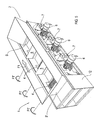
- Figure 1 shows diagrammatically a perspective view of a waste shredder 1, made according to the invention, comprising three rotors 4, with the hopper 2 in an intermediate position, while it is translating as indicated by the arrow F1.
- the waste shredder 1 comprises a supporting structure 12 which bears the loading chamber 3, three rotors 4 placed in seats formed in the bottom wall of the loading chamber 3 and a movable hopper 2, sliding over the loading chamber 3 and provided with a reciprocating translational movement, which has two end walls (B, B') and which carries a plurality of stiff vanes 5 placed in the spaces between the rotors 4: the end walls (B, B') of the hopper 2 and the vanes 5, protruding downwards until they skim the bottom of the loading chamber 3, press the material 8 to be shredded (omitted in Figure 1 ) against the rotors 4, which rotate in the opposite direction to the translational movement of the hopper 2 ( Figures 3-6 ), as disclosed above.
- the material 8 to be shredded is gripped by the teeth of the rotors 4 and cut (in a per se known manner) against counter-blades, adjacent the rotors 4, omitted in the appended figures for the sake of simplicity of the graphic representation.
- the rotors 4 reverse their direction of rotation when the hopper 2 reverses its direction of translation, as disclosed above.
- each motor 6 is carried by supporting means 7 and is coupled to the shaft of one of the rotors 4 by means of riveted flanges or of another per se known rapid coupling/uncoupling means.
- hydraulic motors 6 to drive the rotors 4 proves advantageous since the hydraulic motors are adapted to stand the frequent changes in the direction of rotation required for operating the shredder 1 without presenting the drawbacks (for example, the overheating) presented by the electric motors in the same operating conditions.
- the waste shredder 1 comprises three rotors 4 and two vanes 5 integral with the movable hopper 2 but, without departing from the scope of the invention, the waste shredder 1 can comprise four rotors 4 and three vanes 5, five rotors and four vanes 5 and so on: the shredder 1 generally comprises n rotors 4 and n-1 vanes 5, with n a whole number of two or more.
- Figure 2 shows diagrammatically, from above, the shredder 1 of Figure 1 ; in Figure 2 the loading chamber 3, the movable hopper 2, the end walls (B, B'), the vanes 5 and the rotors 4, coupled to the motors 6 and carried by the supporting means 7, can be seen.
- Figure 3 shows diagrammatically a perspective view of the shredder 1 of Figure 1 , with the hopper 2 that, by translating in the direction indicated by the arrow F in Figure 3 , has reached one end of its translational movement.
- the hopper 2 has a reciprocating translational movement, which makes it pass alternately from the position shown in Figure 3 to that shown in Figure 5 and vice versa.
- the shredder 1 is normally fed by means of a conveyor belt 10: the reciprocating movement of the hopper 2 distributes the material 8 over the whole surface of the loading chamber 3, allowing a balanced operation of the shredding units 11 ( Figure 7 ), comprising at least a rotor 4 and the respective counter-blades.
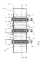
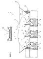
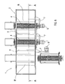
- Figure 5 and Figure 6 (which shows diagrammatically the shredder I of Figure 5 sectioned along the plane A-A of Figure 1 ) show diagrammatically the shredder 1 of Figure 1 with the hopper 2 that, by translating in the direction indicated by the arrow F1, has reached the other end of its translational movement.
- Figure 7 shows diagrammatically a perspective view of the shredder 1 of Figure 1 , with one of the shredder units 11 uncoupled from the respective motor 6 and extracted sideways from the loading chamber 3 to be replaced easily and rapidly, without being obliged to put the whole shredder 1 out of service for a long time.
- Figure 8 shows diagrammatically a top view of the shredder 1 of Figure 7 ; visible in Figure 8 are the hopper 2, the end walls (B, B'), the vanes 5, the unit 11 removed from the loading chamber 3, the related motor 6 carried in a "feathered” position by the means 7 and the other units 11 with their respective rotors 4 connected to the motors 6.
Landscapes
- Engineering & Computer Science (AREA)
- Food Science & Technology (AREA)
- Crushing And Pulverization Processes (AREA)
- Crushing And Grinding (AREA)
- Materials For Medical Uses (AREA)
- Detergent Compositions (AREA)
Abstract
Description
- The present invention refers to a shredder for waste (refuse, production waste, recyclable material, etc.), which comprises:
- a supporting structure which carries a loading chamber;
- tool-carrying rotor, placed in seats formed in the bottom wall of the loading chamber;
- a moveable hopper, sliding over the loading chamber and provided with a reciprocating translational movement, which has two end walls
- The rotors turn in the opposite direction to the translational movement of the hopper and reverse their direction of rotation when the hopper reverses its direction of translation i.e. when the hopper translates in one direction (for example: from left to right) the rotors rotate in one direction (for example: counter clockwise) and vice versa.
- In the treatment of the refuse - and in particular of the urban refuse (solid urban refuse and the like) - it is becoming increasingly and urgently necessary (or, at least, advisable) to subject the refuse, after an adequate selection and separation of the non combustible or otherwise manageable fractions, to a shredding process adapted to make the average dimensions of the remaining material small enough to facilitate use thereof as an alternative fuel in incinerators or cement works furnaces: in fact, the ease of feeding to the furnace and the possibility of homogenisation thus obtained constitute the necessary elements for a correct and profitable management of the combustion heat cycle.
- Moreover, for said management of refuse to be economically viable it is necessary for the throughput of the system and in particular of the shredding section to ensure very high hourly rates, normally of the order of many tonnes/hour.
- These throughputs are normally obtained nowadays with the use of machines that use single large or very large rotors, which have only one direction of rotation and of work and which lead to large installed powers and high investment costs.
- However, this type of machines has the limitation that, when it is necessary to intervene for repairs or maintenance (which are generally very frequent precisely because of the type of work carried out), each intervention is particularly costly in economic and practical terms since it makes necessary for the whole shredding line to be put out of operation, normally for far from negligible periods.
- In particular, in order to ensure the necessary high throughput rates, machines of the prior art have a rotor with a large diameter and length, which has a very large moment of inertia and can therefore be easily damaged by hard, unshreddable foreign bodies (easily present in refuse) which engage the cutting edges of the rotor, forcing the rotor to stop more or less instantly and causing frequent damages or breakages of the cutting tools.
- In many cases, in order to avoid unacceptable interruptions of the service, a reserve machine is made available to replace the machine that is down for repair or for maintenance, considerably increasing the initial investment costs.
- The need has therefore been felt to produce machines for shredding refuse that have such characteristics of simplicity of intervention and of cheapness as to allow the machine down times and costs to be drastically reduced, making the reserve machine superfluous.
- The machine forming the subject matter of the present invention sets out to replace the machines of the prior art, consisting of a single shredding unit (comprising the rotor and the relative counter-blades) having a single cutting direction and a very high throughput per unit - and thus large or very large dimensions and powers - with a much easy-to- manage multi-rotor machine, consisting of a plurality of very small shredding units with two cutting directions.
- Object of the present invention is to produce a waste shredder, comprising at least two rotors, that is adapted to overcome the limits presented by shredders of the prior art; this object is achieved by means of a waste shredder that has the characterising features illustrated in
claim 1. - Further advantageous characteristics of the invention form the subject matter of the dependent claims.
- The invention will now be described with reference to purely exemplifying (and therefore non limiting) embodiments illustrated in the appended figures, wherein:
-
Figure 1 shows diagrammatically a perspective view of a waste shredder, made according to the invention, comprising three rotors, with the hopper in an intermediate position; -
Figure 2 shows diagrammatically a top view of the shredder ofFigure 1 ; -
Figure 3 shows diagrammatically a perspective view of the shredder ofFigure 1 , with the hopper at one end of its translational movement; -
Figure 4 shows diagrammatically the shredder ofFigure 3 sectioned along the plane A-A ofFigure 1 ; -
Figure 5 shows diagrammatically a perspective view of the shredder ofFigure 1 , with the hopper at the other end of its translational movement; -
Figure 6 shows diagrammatically the shredder ofFigure 5 sectioned along the plane A-A ofFigure 1 ; -
Figure 7 shows diagrammatically a perspective view of the shredder ofFigure 1 , with one of the rotors uncoupled from the respective motor and removed from the loading chamber; -
Figure 8 shows diagrammatically a top view of the shredder ofFigure 7 . - In the appended figures corresponding elements will by designated by the same reference numerals.
-
Figure 1 shows diagrammatically a perspective view of awaste shredder 1, made according to the invention, comprising threerotors 4, with thehopper 2 in an intermediate position, while it is translating as indicated by the arrow F1. - The
waste shredder 1 comprises a supportingstructure 12 which bears theloading chamber 3, threerotors 4 placed in seats formed in the bottom wall of theloading chamber 3 and amovable hopper 2, sliding over theloading chamber 3 and provided with a reciprocating translational movement, which has two end walls (B, B') and which carries a plurality ofstiff vanes 5 placed in the spaces between the rotors 4: the end walls (B, B') of thehopper 2 and thevanes 5, protruding downwards until they skim the bottom of theloading chamber 3, press thematerial 8 to be shredded (omitted inFigure 1 ) against therotors 4, which rotate in the opposite direction to the translational movement of the hopper 2 (Figures 3-6 ), as disclosed above. - The
material 8 to be shredded is gripped by the teeth of therotors 4 and cut (in a per se known manner) against counter-blades, adjacent therotors 4, omitted in the appended figures for the sake of simplicity of the graphic representation. - The
rotors 4 reverse their direction of rotation when thehopper 2 reverses its direction of translation, as disclosed above. - Moreover, in
Figure 1 themotors 6 which drive therotors 4 can be seen: eachmotor 6 is carried by supportingmeans 7 and is coupled to the shaft of one of therotors 4 by means of riveted flanges or of another per se known rapid coupling/uncoupling means. - The use of
hydraulic motors 6 to drive therotors 4 proves advantageous since the hydraulic motors are adapted to stand the frequent changes in the direction of rotation required for operating theshredder 1 without presenting the drawbacks (for example, the overheating) presented by the electric motors in the same operating conditions. - In the embodiment described here, the
waste shredder 1 comprises threerotors 4 and twovanes 5 integral with themovable hopper 2 but, without departing from the scope of the invention, thewaste shredder 1 can comprise fourrotors 4 and threevanes 5, five rotors and fourvanes 5 and so on: theshredder 1 generally comprisesn rotors 4 and n-1vanes 5, with n a whole number of two or more. -
Figure 2 shows diagrammatically, from above, theshredder 1 ofFigure 1 ; inFigure 2 theloading chamber 3, themovable hopper 2, the end walls (B, B'), thevanes 5 and therotors 4, coupled to themotors 6 and carried by the supportingmeans 7, can be seen. - Operation of the
shredder 1 will now be described briefly with reference toFigures 3-6 . -
Figure 3 shows diagrammatically a perspective view of theshredder 1 ofFigure 1 , with thehopper 2 that, by translating in the direction indicated by the arrow F inFigure 3 , has reached one end of its translational movement. - As mentioned previously, the
hopper 2 has a reciprocating translational movement, which makes it pass alternately from the position shown inFigure 3 to that shown inFigure 5 and vice versa. - With reference to the
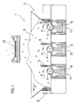
Figures 3 and4 (the last showing diagrammatically the shredder I ofFigure 3 sectioned along the plane A-A ofFigure 1 ), while the hopper 2 (which carries the vanes 5) is moving in the direction of the arrow F the vanes 5 (which move in the same direction;Figure 4 ) and the end wall B of thehopper 2 press thematerial 8 to be shredded against therotors 4, which rotate in the opposite direction to the translational movement of thehopper 2 to grip thematerial 8 and to cut it against the counter-blades. - In the
Figures 3 and4 the direction of rotation of therotors 4 is indicated by the arrows F'. - The
shredder 1 is normally fed by means of a conveyor belt 10: the reciprocating movement of thehopper 2 distributes thematerial 8 over the whole surface of theloading chamber 3, allowing a balanced operation of the shredding units 11 (Figure 7 ), comprising at least arotor 4 and the respective counter-blades. - In
Figures 4 and6 thematerial 8 shredded by eachshredding unit 11 is removed by aconveyor belt 9 placed beneath the shredding unit 11: theconveyor belts 9 can be omitted without departing from the scope of the invention. - When the
hopper 2 has ended its translation in the direction of the arrow F (Figures 3 and4 ), its movement is reversed and, at the same time, the direction of rotation of therotors 4 is reversed: thevanes 5 and the end wall B' of thehopper 2, opposite the wall B, still press thematerial 8 to be shredded against the rotors 4 (Figure 6 ), which still rotate in the opposite direction to the translational movement of thehopper 2 to grip thematerial 8 and to cut it against the counter-blades. -
Figure 5 andFigure 6 (which shows diagrammatically the shredder I ofFigure 5 sectioned along the plane A-A ofFigure 1 ) show diagrammatically theshredder 1 ofFigure 1 with thehopper 2 that, by translating in the direction indicated by the arrow F1, has reached the other end of its translational movement. - In
Figures 5 and6 the direction of rotation of the rotors is indicated by the arrows F1'. -
Figure 7 shows diagrammatically a perspective view of theshredder 1 ofFigure 1 , with one of theshredder units 11 uncoupled from therespective motor 6 and extracted sideways from theloading chamber 3 to be replaced easily and rapidly, without being obliged to put thewhole shredder 1 out of service for a long time. - In fact, it is sufficient to uncouple the
rotor 4 from themotor 6, to rotate themeans 7 which carry themotor 6 into a "feathered" position, to remove the locking means (per se known) of theunit 11 to be repaired or maintained, to slide it out of theloading chamber 3, to replace it with anotherunit 11, to lock it in place by means of the locking means, to couple therotor 4 to themotor 6 and to put theshredder 1 into operation again. -
Figure 8 shows diagrammatically a top view of theshredder 1 ofFigure 7 ; visible inFigure 8 are thehopper 2, the end walls (B, B'), thevanes 5, theunit 11 removed from theloading chamber 3, therelated motor 6 carried in a "feathered" position by themeans 7 and theother units 11 with theirrespective rotors 4 connected to themotors 6. - As is obvious to a person skilled in the art and as has been verified experimentally by the Applicant, throughputs being equal, it is advantageous to replace a machine of the prior art comprising a single rotor (having a single working direction of the rotation) with a machine according to the invention, comprising two or more rotors (having two working directions of rotation) having a smaller power per unit, since:
- the necessary throughput is obtained by summing the individual throughputs of the various shredding units which, because of their limited size, have reduced rotor diameters with limited moments of inertia and thus with a greater ability to withstand sudden stoppages due, for example, to the presence of hard, unshreddable foreign bodies without damages to the rotor shaft and/or to the individual cutting edges;
- the feeding by means of the
hopper 2 provided with a reciprocating movement and the operation by reversing the direction of rotation of the rotors allow the down times normally present in the single-rotor machines to be eliminated; - the presence of the interchangeable
modular units 11 allows anymodular unit 11 that is damaged or that in any case requires maintenance to be replaced in very short times and with very low costs for the materials and the machine down times; - the availability of spare
modular units 11 represents a small investment, amply repaid by the technical and economic advantages described above.
Claims (7)
- A waste shredder (1), characterised in that it comprises at least one supporting structure (12) which carries a loading chamber (3), at least two rotors (4) placed in seats formed in the bottom wall of the loading chamber (3) and a movable hopper (2), sliding above the loading chamber (3) and provided with a reciprocating translational movement, which has two end walls (B, B') and which carries a plurality of stiff vanes (5) placed in the spaces between said rotors (4), the end walls (B, B') of the hopper (2) and the vanes (5) protruding downwards until they skim the bottom of the loading chamber (3) to press the material (8) to be shredded against the rotors (4), which rotate in the opposite direction to the translational movement of the hopper (2).
- A waste shredder (1) as in claim 1, characterised in that the waste shredder (1) comprises n rotors (4) and n-1 vanes (5), n being a whole number of two or more.
- A waste shredder (1) as in claim 1, characterised in that the rotors (4) reverse their direction of rotation when the hopper (2) reverses its direction of translation.
- A waste shredder (1) as in claim 1, characterised in that each rotor (4) is driven by a motor (6).
- A waste shredder (1) as in claim 4, characterised in that the motor (6) is a hydraulic motor.
- A waste shredder (1) as in claim 4, characterised in that each motor (6) is carried by supporting means (7) and is coupled to the shaft of one of the rotors (4) by means of fast coupling/uncoupling means.
- A waste shredder (I) as in claim 1, characterised in that each rotor (4) belongs, together with the counter-blades and with a supporting structure, to a shredding unit (11) that can be extracted sideways from the loading chamber (3).
Applications Claiming Priority (2)
| Application Number | Priority Date | Filing Date | Title |
|---|---|---|---|
| IT001165A ITMI20071165A1 (en) | 2007-06-08 | 2007-06-08 | SHREDDER SHAPE INCLUDING AT LEAST TWO ROTORS |
| PCT/EP2008/001666 WO2008148434A1 (en) | 2007-06-08 | 2008-03-03 | Waste shredder comprising at least two rotors |
Publications (2)
| Publication Number | Publication Date |
|---|---|
| EP2152425A1 EP2152425A1 (en) | 2010-02-17 |
| EP2152425B1 true EP2152425B1 (en) | 2011-04-06 |
Family
ID=39563367
Family Applications (1)
| Application Number | Title | Priority Date | Filing Date |
|---|---|---|---|
| EP08716186A Not-in-force EP2152425B1 (en) | 2007-06-08 | 2008-03-03 | Waste shredder comprising at least two rotors |
Country Status (8)
| Country | Link |
|---|---|
| US (1) | US7905437B2 (en) |
| EP (1) | EP2152425B1 (en) |
| CN (1) | CN101687201B (en) |
| AT (1) | ATE504356T1 (en) |
| DE (1) | DE602008006065D1 (en) |
| ES (1) | ES2360685T3 (en) |
| IT (1) | ITMI20071165A1 (en) |
| WO (1) | WO2008148434A1 (en) |
Families Citing this family (7)
| Publication number | Priority date | Publication date | Assignee | Title |
|---|---|---|---|---|
| PL2857103T3 (en) * | 2013-10-04 | 2019-07-31 | Lindner, Manuel | Comminuting device |
| CN105597896B (en) * | 2015-12-24 | 2018-03-06 | 首钢总公司 | A kind of ore crushes stocking system |
| PL3248687T3 (en) * | 2016-05-23 | 2020-03-31 | Manuel Lindner | Two-shaft shredder having quick change device |
| CN106111248B (en) * | 2016-06-28 | 2019-01-11 | 北京中铁建建筑科技有限公司 | Rubbish pulverizes processing unit |
| US10947453B2 (en) * | 2016-07-12 | 2021-03-16 | Genus Industries, Llc | Method and apparatus for preparing coir |
| DK3446786T3 (en) * | 2017-08-23 | 2020-01-27 | Untha Shredding Tech Gmbh | CRUSHING DEVICE FOR CRUSHING MATERIAL |
| CN112452471B (en) * | 2020-11-10 | 2022-09-27 | 湖南玉和园食品有限公司 | Automatic food processing machinery's crushing mechanism |
Family Cites Families (8)
| Publication number | Priority date | Publication date | Assignee | Title |
|---|---|---|---|---|
| GB1454288A (en) * | 1973-11-07 | 1976-11-03 | Metal Box Co Ltd | Shredding machines |
| US4412659A (en) * | 1981-01-30 | 1983-11-01 | Thermoguard Insulation Co. | Shredding mill |
| US4844363A (en) * | 1987-07-06 | 1989-07-04 | Shredding Systems, Inc. | Hopper ram for shredder |
| US5417375A (en) * | 1994-02-22 | 1995-05-23 | Peterson Pacific Corporation | Material reducing machine |
| US6405949B1 (en) * | 1998-10-28 | 2002-06-18 | Stephen B. Maguire | Shuttle granulator |
| US6773545B2 (en) * | 2000-12-26 | 2004-08-10 | Kimberly-Clark Worldwide, Inc. | Method of forming and metering fluff pulp |
| ITMI20021673A1 (en) * | 2002-07-26 | 2004-01-26 | Satrind Srl | TWO-SHAFT INDUSTRIAL SHREDDER |
| CA2558059C (en) | 2004-01-30 | 2010-06-08 | Mmd Design & Consultancy Limited | Rotating mineral breaker |
-
2007
- 2007-06-08 IT IT001165A patent/ITMI20071165A1/en unknown
-
2008
- 2008-03-03 ES ES08716186T patent/ES2360685T3/en active Active
- 2008-03-03 EP EP08716186A patent/EP2152425B1/en not_active Not-in-force
- 2008-03-03 AT AT08716186T patent/ATE504356T1/en not_active IP Right Cessation
- 2008-03-03 US US12/663,548 patent/US7905437B2/en not_active Expired - Fee Related
- 2008-03-03 WO PCT/EP2008/001666 patent/WO2008148434A1/en not_active Ceased
- 2008-03-03 DE DE602008006065T patent/DE602008006065D1/en active Active
- 2008-03-03 CN CN2008800192377A patent/CN101687201B/en not_active Expired - Fee Related
Also Published As
| Publication number | Publication date |
|---|---|
| DE602008006065D1 (en) | 2011-05-19 |
| WO2008148434A1 (en) | 2008-12-11 |
| ITMI20071165A1 (en) | 2008-12-09 |
| CN101687201A (en) | 2010-03-31 |
| US7905437B2 (en) | 2011-03-15 |
| ES2360685T3 (en) | 2011-06-08 |
| ATE504356T1 (en) | 2011-04-15 |
| CN101687201B (en) | 2011-04-20 |
| EP2152425A1 (en) | 2010-02-17 |
| US20100176233A1 (en) | 2010-07-15 |
Similar Documents
| Publication | Publication Date | Title |
|---|---|---|
| EP2152425B1 (en) | Waste shredder comprising at least two rotors | |
| US8434705B2 (en) | Shredding device with counter knife assembly | |
| JP5684048B2 (en) | 2-axis roll crusher | |
| EP3705183A1 (en) | Crusher for grinding and crushing materials | |
| CN211216811U (en) | Jaw crusher | |
| CN211514772U (en) | Coarse crushing equipment for large garbage | |
| CN100463790C (en) | Scrap tire rubber bould crusher | |
| CN105689069A (en) | A vertical double-pass waste tire shredder | |
| CN202290218U (en) | Automatic feeding and crushing machine | |
| CN112547752B (en) | Method and equipment for recycling main reinforcing steel bars in concrete beam | |
| US20080251619A1 (en) | Shredder for Shredding Recyclable Industrial Waste | |
| JP2815826B2 (en) | Crushing machine | |
| CN102389874B (en) | Full-automatic removing machine for concrete sundries | |
| CN110180650A (en) | Composite building coarse particles machine | |
| CN206549776U (en) | A kind of novel solid waste disintegrating machine | |
| JP2012036537A (en) | Waste paper breaking device | |
| CN101554606B (en) | Garbage crusher | |
| CN217888165U (en) | Big feeding biax system sand machine | |
| CN202752059U (en) | Reversible hammer crusher | |
| CN2776547Y (en) | Breaking mechanism of garbage disintegrator | |
| CN214296800U (en) | Fibre bale breaking machine | |
| CN214765979U (en) | Double-shaft garbage shredder | |
| CN101745453A (en) | Garbage crusher | |
| CN213222614U (en) | Broken recovery unit of resistant firebrick waste material | |
| CN213700200U (en) | A frequency conversion biax breaker for building decoration mixed refuse treatment |
Legal Events
| Date | Code | Title | Description |
|---|---|---|---|
| PUAI | Public reference made under article 153(3) epc to a published international application that has entered the european phase |
Free format text: ORIGINAL CODE: 0009012 |
|
| 17P | Request for examination filed |
Effective date: 20091111 |
|
| AK | Designated contracting states |
Kind code of ref document: A1 Designated state(s): AT BE BG CH CY CZ DE DK EE ES FI FR GB GR HR HU IE IS IT LI LT LU LV MC MT NL NO PL PT RO SE SI SK TR |
|
| AX | Request for extension of the european patent |
Extension state: AL BA MK RS |
|
| DAX | Request for extension of the european patent (deleted) | ||
| GRAP | Despatch of communication of intention to grant a patent |
Free format text: ORIGINAL CODE: EPIDOSNIGR1 |
|
| GRAS | Grant fee paid |
Free format text: ORIGINAL CODE: EPIDOSNIGR3 |
|
| GRAA | (expected) grant |
Free format text: ORIGINAL CODE: 0009210 |
|
| AK | Designated contracting states |
Kind code of ref document: B1 Designated state(s): AT BE BG CH CY CZ DE DK EE ES FI FR GB GR HR HU IE IS IT LI LT LU LV MC MT NL NO PL PT RO SE SI SK TR |
|
| REG | Reference to a national code |
Ref country code: GB Ref legal event code: FG4D |
|
| REG | Reference to a national code |
Ref country code: CH Ref legal event code: EP |
|
| REG | Reference to a national code |
Ref country code: IE Ref legal event code: FG4D |
|
| REF | Corresponds to: |
Ref document number: 602008006065 Country of ref document: DE Date of ref document: 20110519 Kind code of ref document: P |
|
| REG | Reference to a national code |
Ref country code: DE Ref legal event code: R096 Ref document number: 602008006065 Country of ref document: DE Effective date: 20110519 |
|
| REG | Reference to a national code |
Ref country code: ES Ref legal event code: FG2A Ref document number: 2360685 Country of ref document: ES Kind code of ref document: T3 Effective date: 20110608 |
|
| REG | Reference to a national code |
Ref country code: NL Ref legal event code: VDEP Effective date: 20110406 |
|
| PG25 | Lapsed in a contracting state [announced via postgrant information from national office to epo] |
Ref country code: SI Free format text: LAPSE BECAUSE OF FAILURE TO SUBMIT A TRANSLATION OF THE DESCRIPTION OR TO PAY THE FEE WITHIN THE PRESCRIBED TIME-LIMIT Effective date: 20110406 |
|
| LTIE | Lt: invalidation of european patent or patent extension |
Effective date: 20110406 |
|
| PG25 | Lapsed in a contracting state [announced via postgrant information from national office to epo] |
Ref country code: NO Free format text: LAPSE BECAUSE OF FAILURE TO SUBMIT A TRANSLATION OF THE DESCRIPTION OR TO PAY THE FEE WITHIN THE PRESCRIBED TIME-LIMIT Effective date: 20110706 Ref country code: LT Free format text: LAPSE BECAUSE OF FAILURE TO SUBMIT A TRANSLATION OF THE DESCRIPTION OR TO PAY THE FEE WITHIN THE PRESCRIBED TIME-LIMIT Effective date: 20110406 Ref country code: HR Free format text: LAPSE BECAUSE OF FAILURE TO SUBMIT A TRANSLATION OF THE DESCRIPTION OR TO PAY THE FEE WITHIN THE PRESCRIBED TIME-LIMIT Effective date: 20110406 Ref country code: PT Free format text: LAPSE BECAUSE OF FAILURE TO SUBMIT A TRANSLATION OF THE DESCRIPTION OR TO PAY THE FEE WITHIN THE PRESCRIBED TIME-LIMIT Effective date: 20110808 Ref country code: SE Free format text: LAPSE BECAUSE OF FAILURE TO SUBMIT A TRANSLATION OF THE DESCRIPTION OR TO PAY THE FEE WITHIN THE PRESCRIBED TIME-LIMIT Effective date: 20110406 |
|
| PG25 | Lapsed in a contracting state [announced via postgrant information from national office to epo] |
Ref country code: CY Free format text: LAPSE BECAUSE OF FAILURE TO SUBMIT A TRANSLATION OF THE DESCRIPTION OR TO PAY THE FEE WITHIN THE PRESCRIBED TIME-LIMIT Effective date: 20110406 Ref country code: FI Free format text: LAPSE BECAUSE OF FAILURE TO SUBMIT A TRANSLATION OF THE DESCRIPTION OR TO PAY THE FEE WITHIN THE PRESCRIBED TIME-LIMIT Effective date: 20110406 Ref country code: IS Free format text: LAPSE BECAUSE OF FAILURE TO SUBMIT A TRANSLATION OF THE DESCRIPTION OR TO PAY THE FEE WITHIN THE PRESCRIBED TIME-LIMIT Effective date: 20110806 Ref country code: GR Free format text: LAPSE BECAUSE OF FAILURE TO SUBMIT A TRANSLATION OF THE DESCRIPTION OR TO PAY THE FEE WITHIN THE PRESCRIBED TIME-LIMIT Effective date: 20110707 Ref country code: LV Free format text: LAPSE BECAUSE OF FAILURE TO SUBMIT A TRANSLATION OF THE DESCRIPTION OR TO PAY THE FEE WITHIN THE PRESCRIBED TIME-LIMIT Effective date: 20110406 Ref country code: AT Free format text: LAPSE BECAUSE OF FAILURE TO SUBMIT A TRANSLATION OF THE DESCRIPTION OR TO PAY THE FEE WITHIN THE PRESCRIBED TIME-LIMIT Effective date: 20110406 Ref country code: BE Free format text: LAPSE BECAUSE OF FAILURE TO SUBMIT A TRANSLATION OF THE DESCRIPTION OR TO PAY THE FEE WITHIN THE PRESCRIBED TIME-LIMIT Effective date: 20110406 |
|
| PG25 | Lapsed in a contracting state [announced via postgrant information from national office to epo] |
Ref country code: NL Free format text: LAPSE BECAUSE OF FAILURE TO SUBMIT A TRANSLATION OF THE DESCRIPTION OR TO PAY THE FEE WITHIN THE PRESCRIBED TIME-LIMIT Effective date: 20110406 |
|
| PG25 | Lapsed in a contracting state [announced via postgrant information from national office to epo] |
Ref country code: EE Free format text: LAPSE BECAUSE OF FAILURE TO SUBMIT A TRANSLATION OF THE DESCRIPTION OR TO PAY THE FEE WITHIN THE PRESCRIBED TIME-LIMIT Effective date: 20110406 Ref country code: CZ Free format text: LAPSE BECAUSE OF FAILURE TO SUBMIT A TRANSLATION OF THE DESCRIPTION OR TO PAY THE FEE WITHIN THE PRESCRIBED TIME-LIMIT Effective date: 20110406 |
|
| PLBE | No opposition filed within time limit |
Free format text: ORIGINAL CODE: 0009261 |
|
| STAA | Information on the status of an ep patent application or granted ep patent |
Free format text: STATUS: NO OPPOSITION FILED WITHIN TIME LIMIT |
|
| PG25 | Lapsed in a contracting state [announced via postgrant information from national office to epo] |
Ref country code: DK Free format text: LAPSE BECAUSE OF FAILURE TO SUBMIT A TRANSLATION OF THE DESCRIPTION OR TO PAY THE FEE WITHIN THE PRESCRIBED TIME-LIMIT Effective date: 20110406 Ref country code: SK Free format text: LAPSE BECAUSE OF FAILURE TO SUBMIT A TRANSLATION OF THE DESCRIPTION OR TO PAY THE FEE WITHIN THE PRESCRIBED TIME-LIMIT Effective date: 20110406 Ref country code: PL Free format text: LAPSE BECAUSE OF FAILURE TO SUBMIT A TRANSLATION OF THE DESCRIPTION OR TO PAY THE FEE WITHIN THE PRESCRIBED TIME-LIMIT Effective date: 20110406 Ref country code: RO Free format text: LAPSE BECAUSE OF FAILURE TO SUBMIT A TRANSLATION OF THE DESCRIPTION OR TO PAY THE FEE WITHIN THE PRESCRIBED TIME-LIMIT Effective date: 20110406 |
|
| 26N | No opposition filed |
Effective date: 20120110 |
|
| REG | Reference to a national code |
Ref country code: DE Ref legal event code: R097 Ref document number: 602008006065 Country of ref document: DE Effective date: 20120110 |
|
| PGFP | Annual fee paid to national office [announced via postgrant information from national office to epo] |
Ref country code: GB Payment date: 20120329 Year of fee payment: 5 |
|
| PG25 | Lapsed in a contracting state [announced via postgrant information from national office to epo] |
Ref country code: MC Free format text: LAPSE BECAUSE OF NON-PAYMENT OF DUE FEES Effective date: 20120331 |
|
| REG | Reference to a national code |
Ref country code: CH Ref legal event code: PL |
|
| REG | Reference to a national code |
Ref country code: IE Ref legal event code: MM4A |
|
| PG25 | Lapsed in a contracting state [announced via postgrant information from national office to epo] |
Ref country code: IE Free format text: LAPSE BECAUSE OF NON-PAYMENT OF DUE FEES Effective date: 20120303 Ref country code: LI Free format text: LAPSE BECAUSE OF NON-PAYMENT OF DUE FEES Effective date: 20120331 Ref country code: CH Free format text: LAPSE BECAUSE OF NON-PAYMENT OF DUE FEES Effective date: 20120331 |
|
| PG25 | Lapsed in a contracting state [announced via postgrant information from national office to epo] |
Ref country code: BG Free format text: LAPSE BECAUSE OF FAILURE TO SUBMIT A TRANSLATION OF THE DESCRIPTION OR TO PAY THE FEE WITHIN THE PRESCRIBED TIME-LIMIT Effective date: 20110706 |
|
| PGFP | Annual fee paid to national office [announced via postgrant information from national office to epo] |
Ref country code: ES Payment date: 20120302 Year of fee payment: 5 |
|
| PG25 | Lapsed in a contracting state [announced via postgrant information from national office to epo] |
Ref country code: MT Free format text: LAPSE BECAUSE OF FAILURE TO SUBMIT A TRANSLATION OF THE DESCRIPTION OR TO PAY THE FEE WITHIN THE PRESCRIBED TIME-LIMIT Effective date: 20110406 |
|
| GBPC | Gb: european patent ceased through non-payment of renewal fee |
Effective date: 20130303 |
|
| PG25 | Lapsed in a contracting state [announced via postgrant information from national office to epo] |
Ref country code: GB Free format text: LAPSE BECAUSE OF NON-PAYMENT OF DUE FEES Effective date: 20130303 |
|
| PG25 | Lapsed in a contracting state [announced via postgrant information from national office to epo] |
Ref country code: TR Free format text: LAPSE BECAUSE OF FAILURE TO SUBMIT A TRANSLATION OF THE DESCRIPTION OR TO PAY THE FEE WITHIN THE PRESCRIBED TIME-LIMIT Effective date: 20110406 |
|
| PG25 | Lapsed in a contracting state [announced via postgrant information from national office to epo] |
Ref country code: LU Free format text: LAPSE BECAUSE OF NON-PAYMENT OF DUE FEES Effective date: 20120303 |
|
| REG | Reference to a national code |
Ref country code: ES Ref legal event code: FD2A Effective date: 20140610 |
|
| PG25 | Lapsed in a contracting state [announced via postgrant information from national office to epo] |
Ref country code: HU Free format text: LAPSE BECAUSE OF FAILURE TO SUBMIT A TRANSLATION OF THE DESCRIPTION OR TO PAY THE FEE WITHIN THE PRESCRIBED TIME-LIMIT Effective date: 20080303 |
|
| PG25 | Lapsed in a contracting state [announced via postgrant information from national office to epo] |
Ref country code: ES Free format text: LAPSE BECAUSE OF NON-PAYMENT OF DUE FEES Effective date: 20130304 |
|
| REG | Reference to a national code |
Ref country code: FR Ref legal event code: PLFP Year of fee payment: 8 |
|
| REG | Reference to a national code |
Ref country code: FR Ref legal event code: PLFP Year of fee payment: 9 |
|
| REG | Reference to a national code |
Ref country code: FR Ref legal event code: PLFP Year of fee payment: 10 |
|
| PGFP | Annual fee paid to national office [announced via postgrant information from national office to epo] |
Ref country code: FR Payment date: 20170327 Year of fee payment: 10 |
|
| PGFP | Annual fee paid to national office [announced via postgrant information from national office to epo] |
Ref country code: IT Payment date: 20170228 Year of fee payment: 10 |
|
| PGFP | Annual fee paid to national office [announced via postgrant information from national office to epo] |
Ref country code: DE Payment date: 20170330 Year of fee payment: 10 |
|
| REG | Reference to a national code |
Ref country code: DE Ref legal event code: R119 Ref document number: 602008006065 Country of ref document: DE |
|
| PG25 | Lapsed in a contracting state [announced via postgrant information from national office to epo] |
Ref country code: DE Free format text: LAPSE BECAUSE OF NON-PAYMENT OF DUE FEES Effective date: 20181002 |
|
| PG25 | Lapsed in a contracting state [announced via postgrant information from national office to epo] |
Ref country code: IT Free format text: LAPSE BECAUSE OF NON-PAYMENT OF DUE FEES Effective date: 20180303 |
|
| PG25 | Lapsed in a contracting state [announced via postgrant information from national office to epo] |
Ref country code: FR Free format text: LAPSE BECAUSE OF NON-PAYMENT OF DUE FEES Effective date: 20180331 |