CN101858024A - Washing and Drying Machines and Dryers - Google Patents

Washing and Drying Machines and Dryers Download PDF

Info

Publication number
CN101858024A
CN101858024A CN 201010104746 CN201010104746A CN101858024A CN 101858024 A CN101858024 A CN 101858024A CN 201010104746 CN201010104746 CN 201010104746 CN 201010104746 A CN201010104746 A CN 201010104746A CN 101858024 A CN101858024 A CN 101858024A
Authority
CN
China
Prior art keywords
outlet
air
warm air
drying
blowing
Prior art date
Legal status (The legal status is an assumption and is not a legal conclusion. Google has not performed a legal analysis and makes no representation as to the accuracy of the status listed.)
Granted
Application number
CN 201010104746
Other languages
Chinese (zh)
Other versions
CN101858024B (en
Inventor
山下太一郎
木村刚
黑泽真理
小池敏文
Current Assignee (The listed assignees may be inaccurate. Google has not performed a legal analysis and makes no representation or warranty as to the accuracy of the list.)
Hitachi Global Life Solutions Inc
Original Assignee
Hitachi Appliances Inc
Priority date (The priority date is an assumption and is not a legal conclusion. Google has not performed a legal analysis and makes no representation as to the accuracy of the date listed.)
Filing date
Publication date
Application filed by Hitachi Appliances Inc filed Critical Hitachi Appliances Inc
Publication of CN101858024A publication Critical patent/CN101858024A/en
Application granted granted Critical
Publication of CN101858024B publication Critical patent/CN101858024B/en
Expired - Fee Related legal-status Critical Current
Anticipated expiration legal-status Critical

Links

Images

Landscapes

  • Detail Structures Of Washing Machines And Dryers (AREA)
  • Main Body Construction Of Washing Machines And Laundry Dryers (AREA)
  • Control Of Washing Machine And Dryer (AREA)

Abstract

本发明提供一种洗涤干燥机和干燥机,其能够提高洗涤物的干燥、干燥质量性能,并实现消耗电力的降低。洗涤干燥机(1)具有:外槽(4),其在一个面上具有开口(4a),而且该外槽(4)被弹性地支承;通过电动机(8)驱动旋转的内槽(5),其能够旋转地轴支承于外槽(4)的内部,并且在一端具有开口(5a);盖体(7),其开闭外槽(4)的开口(4a);吹出口(37A、37B),其在干燥工序中将暖风(50)吹入到内槽(5)的内部,并且改变该吹入面积和该吹入方向中的至少一方;风道管(15、13、24、25、23),其以设于外槽(4)的排气口(12)为上游,以上述吹出口为下游,该风道管形成将排气口(12)和上述吹出口连接起来的空气流道;送风风扇(18),其输送风道管内的空气;以及加热单元(21),其对空气进行加热使之成为暖风(50)。
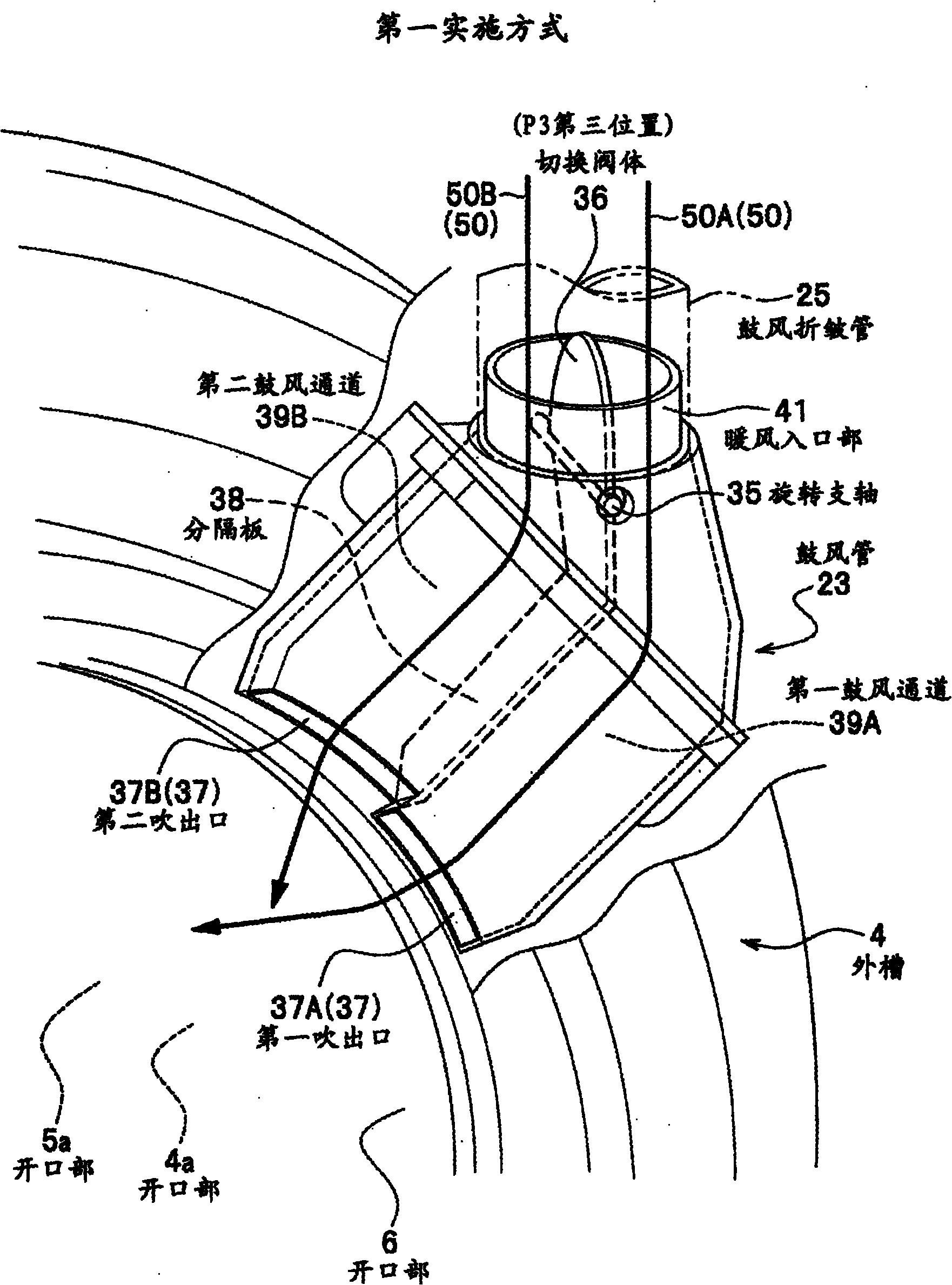
Figure 201010104746

The present invention provides a washing and drying machine and a drying machine capable of improving the drying and drying quality performance of laundry and reducing power consumption. The washing and drying machine (1) has: an outer tank (4) having an opening (4a) on one side, and the outer tank (4) is elastically supported; an inner tank (5) driven to rotate by a motor (8) , which can be rotatably supported inside the outer tank (4), and has an opening (5a) at one end; a cover (7), which opens and closes the opening (4a) of the outer tank (4); blowing outlets ( 37A, 37B ), which blows warm air (50) into the interior of the inner tank (5) during the drying process, and changes at least one of the blowing area and the blowing direction; the air duct pipes (15, 13, 24, 25, 23), it is located at the exhaust port (12) of the outer tank (4) as the upstream, and the above-mentioned blowing outlet is downstream, and the air duct pipe forms the air outlet (12) and the above-mentioned blowing outlet. An air flow channel; a blower fan (18), which delivers the air in the air duct pipe; and a heating unit (21), which heats the air to become warm air (50).

Figure 201010104746

Description

洗涤干燥机以及干燥机 Washing and Drying Machines and Dryers

技术领域technical field

本发明涉及进行衣物等洗涤物的干燥的洗涤干燥机和干燥机。The present invention relates to a washing and drying machine and a drying machine for drying laundry such as clothes.

背景技术Background technique

滚筒式洗涤干燥机将滚筒以能够绕水平或者大致水平的旋转轴旋转的方式配置在外槽内,绕该旋转轴驱动滚筒旋转以对洗涤物进行洗涤、漂洗、脱水和干燥,其中上述外槽水平或者大致水平地倾斜配置。The drum type washing and drying machine arranges the drum in the outer tank in a manner that can rotate around a horizontal or substantially horizontal rotating shaft, and drives the drum to rotate around the rotating shaft to wash, rinse, dehydrate and dry the laundry, wherein the outer tank is horizontal Alternatively, it may be arranged inclined substantially horizontally.

这里,为了使含有水分的洗涤物干燥,将含有湿气的滚筒内部的空气排出到外槽之外,通过除湿单元进行除湿之后,利用加热单元进行加热使之干燥,利用风扇将加压、加速后的该干燥了的空气吹到滚筒内部,由此使水分从洗涤物蒸发,通过进行这样的干燥循环,来使潮湿的洗涤物干燥。Here, in order to dry the laundry containing moisture, the air inside the drum containing moisture is discharged out of the outer tank, dehumidified by the dehumidification unit, heated by the heating unit to dry it, and pressurized and accelerated by the fan. The dried air is blown into the drum to evaporate moisture from the laundry, and the wet laundry is dried by performing such a drying cycle.

以往,专利文献1所记载的洗涤干燥机公开了这样的结构:具有迂回通道,由送风机输送的空气的一部分流经该迂回通道而不从加热单元通过,而且使该迂回通道的通道截面积可变,并且根据洗涤容量的大小、布料、外箱内温度而可以变化。In the past, the washing and drying machine described in Patent Document 1 discloses such a structure: there is a detour passage, a part of the air sent by the blower flows through the detour passage without passing through the heating unit, and the passage cross-sectional area of the detour passage can be reduced. It can change according to the size of the washing capacity, the fabric, and the temperature inside the outer box.

但是,对于用于提高干燥的质量以及提高干燥的效率的结构,则完全没有记载。However, there is no description at all about the structure for improving the quality of drying and improving the efficiency of drying.

专利文献1:特开2007-330354号公报Patent Document 1: JP-A-2007-330354

另外,为了促进水分从衣物等洗涤物蒸发以缩短干燥时间,有时存在这样的情况:扩大吹出口的面积以减小吹出口处的风道阻力,虽然风速有所降低,但是增大风量是更优选的。In addition, in order to promote the evaporation of water from laundry and other laundry to shorten the drying time, sometimes there is such a situation: to expand the area of the outlet to reduce the air passage resistance at the outlet, although the wind speed has decreased, but increasing the air volume is more effective. preferred.

另外如果增加风扇的旋转速度,暖风量会增加,但是另一方面,风扇噪音会增加,而且风扇电动机的消耗的电力也会增加。In addition, if the rotation speed of the fan is increased, the amount of warm air will increase, but on the other hand, the noise of the fan will increase, and the power consumption of the fan motor will also increase.

另外,若限制喷嘴以提高风速,则对减少衣物等洗涤物的褶皱有效,但是喷嘴部分的压力损失会增大,因此,需要使风扇高速旋转,消耗电力会增大,而且风扇噪音也会增大,因此,以上内容成为技术问题。In addition, if the nozzle is restricted to increase the wind speed, it is effective to reduce the wrinkles of laundry such as clothes, but the pressure loss at the nozzle part will increase, so the fan needs to be rotated at a high speed, the power consumption will increase, and the fan noise will also increase. Large, therefore, the above becomes a technical issue.

发明内容Contents of the invention

鉴于上述实际情况,本发明提供一种通过使暖风吹出口的面积可变或者使暖风的吹出方向可变来加快洗涤物的干燥和提高干燥质量性能、并且能降低消耗电力的洗涤干燥机和干燥机。In view of the above actual situation, the present invention provides a washing and drying machine that speeds up drying of laundry, improves drying quality performance, and reduces power consumption by changing the area of the warm air outlet or changing the blowing direction of the warm air. and dryer.

为了达成上述目的,本发明第一方面的洗涤干燥机具备:外槽,其在一个面上具有开口,而且该外槽被弹性地支承;内槽,其能够旋转地轴支承于外槽的内部,并且在一端具有与外槽的开口对置的开口;盖体,其开闭外槽的开口;电动机,其驱动内槽旋转;吹出口,其在干燥工序中将暖风吹入到内槽的内部,并且改变该吹入面积和该吹入方向中的至少一方;风道管,其以设于外槽的排气口为上游,以吹出口为下游,该风道管形成将排气口和吹出口连接起来的空气流道;送风风扇,其输送风道管内的空气;以及加热单元,其对空气进行加热使之成为暖风。In order to achieve the above object, the washing and drying machine according to the first aspect of the present invention is provided with: an outer tank having an opening on one surface, and the outer tank is elastically supported; an inner tank, which is rotatably pivotally supported inside the outer tank, And there is an opening opposite to the opening of the outer tank at one end; a cover body, which opens and closes the opening of the outer tank; a motor, which drives the inner tank to rotate; an outlet, which blows warm air into the inner tank during the drying process. Inside, and at least one of the blowing area and the blowing direction is changed; the air duct pipe is upstream of the air outlet located in the outer tank and downstream of the air outlet, and the air duct pipe forms the air outlet The air channel connected with the air outlet; the air supply fan, which delivers the air in the air duct pipe; and the heating unit, which heats the air to become warm air.

本发明第二方面的干燥机具备:外槽,其在一个面上具有开口,而且该外槽被弹性地支承;内槽,其能够旋转地轴支承于外槽的内部,并且在一端具有与外槽的开口对置的开口;盖体,其开闭外槽的开口;电动机,其驱动内槽旋转;吹出口,其在干燥工序中将暖风吹入到内槽的内部,并且改变该吹入面积和该吹入方向中的至少一方;风道管,其以设于外槽的排气口为上游,以吹出口为下游,该风道管形成将排气口和吹出口连接起来的空气流道;送风风扇,其输送风道管内的空气;以及加热单元,其对空气进行加热使之成为暖风。The drying machine according to the second aspect of the present invention includes: an outer tank having an opening on one surface and elastically supporting the outer tank; an inner tank which is rotatably supported inside the outer tank and has a The opening opposite to the opening of the tank; the cover, which opens and closes the opening of the outer tank; the motor, which drives the inner tank to rotate; the blower port, which blows warm air into the inner tank during the drying process, and changes the blowing temperature. At least one of the inlet area and the blowing direction; the air duct pipe, which takes the exhaust port located on the outer tank as the upstream, and takes the blowing outlet as the downstream, and the air duct pipe forms a link connecting the exhaust port and the blowing outlet. an air flow channel; a blower fan, which delivers air in the air duct tube; and a heating unit, which heats the air to become warm air.

根据本发明,能够实现加快洗涤物的干燥和提高干燥质量性能、并且能够降低消耗电力的洗涤干燥机和干燥机。According to the present invention, it is possible to realize a washing and drying machine and a drying machine capable of accelerating drying of laundry, improving dry quality performance, and reducing power consumption.

附图说明Description of drawings

图1是表示本发明的实施方式的滚筒式洗涤干燥机的整体和内部结构的包括局部剖切的立体图。Fig. 1 is a partially cutaway perspective view showing the overall and internal structure of a drum-type washing and drying machine according to an embodiment of the present invention.

图2是表示实施方式的滚筒式洗涤干燥机的内部结构的包括局部剖切的后视图。Fig. 2 is a partially cutaway rear view showing the internal structure of the drum-type washing and drying machine according to the embodiment.

图3是表示实施方式的滚筒式洗涤干燥机的内部结构的包括局部剖切的右视图。Fig. 3 is a partially cutaway right side view showing the internal structure of the drum-type washing and drying machine according to the embodiment.

图4是表示实施方式的滚筒式洗涤干燥机的内部结构的包括局部剖切的俯视图。Fig. 4 is a partially cutaway plan view showing the internal structure of the drum-type washing and drying machine according to the embodiment.

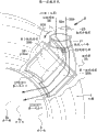
图5是通过滚筒式洗涤干燥机的鼓风管的结构和切换阀体对暖风的切换动作来改变暖风的吹出方向的第一实施方式的立体图。5 is a perspective view of a first embodiment in which the blowing direction of warm air is changed by the structure of the blast pipe of the drum type washing and drying machine and the switching operation of the switching valve body for the warm air.

图6是通过滚筒式洗涤干燥机的鼓风管的结构和切换阀体对暖风的切换动作来改变暖风的吹出方向的第一实施方式的立体图。6 is a perspective view of a first embodiment in which the blowing direction of warm air is changed by the structure of the blast pipe of the drum type washing and drying machine and the switching operation of the switching valve body for the warm air.

图7是通过滚筒式洗涤干燥机的鼓风管的结构和切换阀体对暖风的切换动作来改变暖风的吹出方向的第一实施方式的立体图。7 is a perspective view of a first embodiment in which the blowing direction of warm air is changed by the structure of the blast pipe of the drum type washing and drying machine and the switching operation of the switching valve body for the warm air.

图8是通过滚筒式洗涤干燥机的鼓风管的结构和切换阀体对暖风的切换动作来改变暖风的吹出方向的第二实施方式的立体图。8 is a perspective view of a second embodiment in which the blowing direction of warm air is changed by the structure of the blast pipe of the drum-type washing and drying machine and the switching operation of the switching valve body for the warm air.

图9是通过滚筒式洗涤干燥机的鼓风管的结构和切换阀体对暖风的切换动作来改变暖风的吹出方向的第二实施方式的立体图。9 is a perspective view of a second embodiment in which the blowing direction of warm air is changed by the structure of the blast pipe of the drum type washing and drying machine and the switching operation of the switching valve body for the warm air.

图10是通过滚筒式洗涤干燥机的鼓风管的结构和切换阀体对暖风的切换动作来改变暖风的吹出方向的第二实施方式的立体图。10 is a perspective view of a second embodiment in which the blowing direction of warm air is changed by the structure of the blast pipe of the drum-type washing and drying machine and the switching operation of the switching valve body for the warm air.

图11是从背面侧观察实施方式的滚筒式洗涤干燥机的图5和图8所示的鼓风管的立体图,是表示切换阀体的驱动结构的一例的立体图。11 is a perspective view of the blower duct shown in FIGS. 5 and 8 as viewed from the rear side of the drum-type washing and drying machine according to the embodiment, and is a perspective view showing an example of a driving structure of a switching valve body.

图12是从背面侧观察实施方式的滚筒式洗涤干燥机的图7和图10示的鼓风管的立体图,是表示切换阀体的驱动结构的一例的立体图。12 is a perspective view of the blower duct shown in FIGS. 7 and 10 as viewed from the rear side of the drum-type washing and drying machine according to the embodiment, and is a perspective view showing an example of a driving structure of a switching valve body.

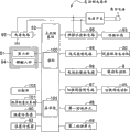
图13是表示控制方式的滚筒式洗涤干燥机的控制系统的结构的方框图。Fig. 13 is a block diagram showing the configuration of a control system of the drum-type washer-dryer in the control mode.

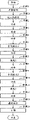
图14是表示实施方式的滚筒式洗涤干燥机的标准过程(course)的概略流程图的图。Fig. 14 is a diagram showing a schematic flowchart of a course of the drum-type washing and drying machine according to the embodiment.

图15是从前表面侧观察第二实施方式的变形方式的鼓风管附近的包括主要部分剖视图的立体图。Fig. 15 is a perspective view including a sectional view of main parts, as viewed from the front side, in the vicinity of the blast pipe in a modified form of the second embodiment.

标号说明Label description

1滚筒式洗涤干燥机(洗涤干燥机)1 drum type washing and drying machine (washing and drying machine)

4外槽4 outer slots

4a开口部(外槽的开口)4a Opening (opening of outer tank)

5滚筒(内槽)5 rollers (inner tank)

5a开口部(内槽的开口)5a Opening (opening of inner tank)

6开口部(外槽的开口)6 Opening (opening of outer tank)

7盖(盖体)7 cover (cover body)

8驱动电动机(电动机)8 drive motor (electric motor)

11干燥单元(风道管、过滤器、送风风扇、加热单元)11 drying unit (air duct, filter, air supply fan, heating unit)

12排气口12 exhaust port

13除湿管(风道管)13 Dehumidification pipe (air duct pipe)

14洗涤物14 washings

15折皱管(风道管)15 corrugated tube (air duct tube)

16过滤器16 filters

18风扇(送风风扇)18 fans (air supply fan)

20风扇驱动电动机(风扇旋转速度控制单元)20 fan drive motor (fan rotation speed control unit)

21加热器(加热单元)21 heater (heating unit)

23鼓风管(风道管)23 blast pipe (air duct pipe)

24连接风道(风道管)24 connecting air duct (air duct pipe)

25鼓风折皱管(风道管)25 blowing corrugated tube (air duct tube)

35旋转支轴(支点)35 rotating fulcrum (fulcrum)

36切换阀体(切换部件)36 switching valve body (switching parts)

37吹出口(第一吹出口、第二吹出口)37 outlets (first outlet, second outlet)

37A第一吹出口37A first outlet

37B第二吹出口37B Second outlet

38分隔板(分隔壁)38 partition board (partition wall)

39鼓风通道(风道管)39 blast channel (air duct pipe)

39A第一鼓风通道(风道管)39A The first blast channel (air duct pipe)

39B第二鼓风通道(风道管)39B Second blast channel (air duct pipe)

41暖风入口部(风道管)41 Warm air inlet (air duct pipe)

48第一检测单元(切换阀位置选择单元)48 The first detection unit (switching valve position selection unit)

49第二检测单元(切换阀位置选择单元)49 Second detection unit (switching valve position selection unit)

50暖风50 warm air

50A暖风50A warm air

50B暖风50B warm air

50E暖风50E warm air

50F暖风50F warm air

51s操作按钮开关(干燥模式选择单元)51s operation button switch (drying mode selection unit)

90温度传感器(切换阀位置选择单元)90 temperature sensor (switching valve position selection unit)

92温度传感器(切换阀位置选择单元)92 temperature sensor (switching valve position selection unit)

94键输入部(干燥模式选择单元)94-key input unit (drying mode selection unit)

98送风控制电路(风扇旋转速度控制单元)98 air supply control circuit (fan rotation speed control unit)

100微型计算机(风扇旋转速度控制单元、切换阀位置选择单元、干燥模式选择单元)100 microcomputers (fan rotation speed control unit, switching valve position selection unit, drying mode selection unit)

C控制电路部(风扇旋转速度控制单元、切换阀位置选择单元、干燥模式选择单元)C control circuit part (fan rotation speed control unit, switching valve position selection unit, drying mode selection unit)

P1第一位置P1 first position

P2第二位置P2 second position

P3第三位置P3 third position

具体实施方式Detailed ways

下面参照附图对本发明的实施方式进行说明。Embodiments of the present invention will be described below with reference to the drawings.

图1是表示本发明所涉及的实施方式的滚筒式洗涤干燥机1的整体和内部结构的包括局部剖切的立体图,图2是表示图1所示的滚筒式洗涤干燥机1的内部结构的包括局部剖切的后视图,图3是表示图1所示的滚筒式洗涤干燥机1的内部结构的包括局部剖切的右视图,图4是表示图1所示的滚筒式洗涤干燥机1的内部结构的包括局部剖切的俯视图。1 is a perspective view showing the overall and internal structure of a drum-type washing and drying machine 1 according to an embodiment of the present invention, including a partially cutaway perspective view, and FIG. 2 is a perspective view showing the internal structure of the drum-type washing and drying machine 1 shown in FIG. Including a partial cutaway rear view, Fig. 3 is a right view including a partial cutaway showing the internal structure of the drum type washing and drying machine 1 shown in Fig. A top view of the internal structure including a partial cutaway.

【滚筒式洗涤干燥机1的概要】【Overview of drum type washing and drying machine 1】

实施方式的滚筒式洗涤干燥机1(图1~图4)在滚筒5旋转的同时进行供水和排水,由此,对投入到滚筒5内的洗涤物14(参照图3)进行洗涤、漂洗和脱水,然后在滚筒5旋转的同时向洗涤物14吹暖风(50(50A、50B))(参照图3)来进行干燥,从而自动连续地进行洗涤物14的洗涤、漂洗、脱水和干燥。The drum type washing and drying machine 1 ( FIGS. 1 to 4 ) of the embodiment performs water supply and drainage while the drum 5 rotates, thereby washing, rinsing and washing the laundry 14 (see FIG. 3 ) put into the drum 5 . Dehydration, and then drying by blowing warm air (50 (50A, 50B)) (see FIG. 3 ) to the laundry 14 while the drum 5 is rotating, thereby automatically and continuously washing, rinsing, dehydrating and drying the laundry 14.

图5到图7是通过滚筒式洗涤干燥机1的鼓风管23的结构和切换阀体36对吹向洗涤物14的暖风50A、50B进行的切换动作(参照图5、图7的箭头40A、40B),来改变暖风50A、50B的吹出方向的第一实施方式的立体图。5 to 7 show the switching action of the warm air 50A, 50B blowing to the laundry 14 through the structure of the blast pipe 23 of the drum type washing and drying machine 1 and the switching valve body 36 (see arrows in FIGS. 5 and 7 ). 40A, 40B), to change the blowing direction of the warm air 50A, 50B perspective view of the first embodiment.

图3和图4所示的滚筒式洗涤干燥机1的鼓风管23中设置有切换阀体36,该切换阀体36能够转动地轴支承于暖风入口部41(参照图5~图7),该切换阀体36形成为从旋转支轴35延伸向暖风50A、50B流动的上游侧(图示上侧)或者加热器21侧的形状。In the blast pipe 23 of the drum type washing and drying machine 1 shown in FIGS. 3 and 4 , a switching valve body 36 is provided, and the switching valve body 36 is rotatably supported on the hot air inlet portion 41 (see FIGS. 5 to 7 ). The switching valve body 36 is formed in a shape extending from the rotation shaft 35 toward the upstream side (upper side in the drawing) where the warm air 50A, 50B flows or toward the heater 21 side.

如图5、图6所示,从鼓风管23中的切换阀体36到外槽4的开口部4a为止的风道中,形成有通过分隔板38分隔成两个的第一鼓风通道39A和第二鼓风通道39B,第一鼓风通道39A和第二鼓风通道39B分别与朝向滚筒5的内部开口的第一吹出口37A和第二吹出口37B连接。As shown in FIGS. 5 and 6 , in the air passage from the switching valve body 36 in the blowing pipe 23 to the opening 4 a of the outer tank 4 , a first blowing passage divided into two by a partition plate 38 is formed. 39A and the second blowing passage 39B, the first blowing passage 39A and the second blowing passage 39B are respectively connected to the first blowing port 37A and the second blowing port 37B opened toward the inside of the drum 5 .

在干燥运转时,从鼓风管23的第一和第二吹出口37A、37B对洗涤物14吹暖风50(50A、50B)来进行干燥。During the drying operation, warm air 50 ( 50A, 50B) is blown to laundry 14 from first and second outlets 37A, 37B of air blowing duct 23 to dry laundry 14 .

在干燥运转时,通过使鼓风管23中的切换阀体36进行转动动作(参照图5、图7中的箭头40A、40B),来切换第一吹出口37A和第二吹出口37B,由此来适当地改变暖风50A、50B的风向、风速、和风量等。During dry operation, the switching valve body 36 in the blast pipe 23 is rotated (refer to arrows 40A and 40B in FIGS. In this way, the wind direction, wind speed, and air volume of the warm air 50A, 50B can be appropriately changed.

由此,能够使用于向滚筒5内部吹干燥的暖风50(50A、50B)从而使洗涤物14干燥的暖风吹出口(第一和第二吹出口37A、37B)的风向或面积可变。Thereby, the wind direction or area of the warm air outlets (first and second outlets 37A, 37B) for drying the laundry 14 by blowing the dry warm air 50 (50A, 50B) inside the drum 5 can be changed. .

下面对滚筒式洗涤干燥机1的结构进行详细说明。The structure of the drum type washing and drying machine 1 will be described in detail below.

【滚筒式洗涤干燥机1的外装】[Exterior of drum type washing and drying machine 1]

图1所示的滚筒式洗涤干燥机1在作为基础支承部件的基座3的上部,通过螺钉固定等安装有组合钢板和树脂成型品而构成的作为支承部件的外框(未图示)。In the drum type washing and drying machine 1 shown in FIG. 1 , an outer frame (not shown) as a supporting member composed of a combination of steel plates and resin moldings is mounted on the upper portion of a base 3 as a basic supporting member by screwing or the like.

在外框上,在其前表面设置有构成前表面的壳体的前表面罩c1和用于取放洗涤物14的能够开闭的盖7,并且在外框的背面设置有构成背面的壳体的背面罩c2。通过这些前表面罩c1、背面罩c2和基座3等构成洗涤干燥机1的壳体。On the outer frame, a front cover c1 and an openable and closable cover 7 for taking in and out of the laundry 14 are provided on the front surface of the outer frame, and the rear surface of the outer frame is provided with a front cover c1 that constitutes a rear casing. Back cover c2. The casing of the washing and drying machine 1 is constituted by these front cover c1, rear cover c2, base 3, and the like.

在前表面罩c1的上部,设置有用于由使用者进行滚筒式洗涤干燥机1的操作的操作面板51。An operation panel 51 for a user to operate the drum-type washing and drying machine 1 is provided on the upper portion of the front cover c1.

在操作面板51上配设有:负责滚筒式洗涤干燥机1的电源的接通/断开的电源开关;用于选择洗涤·干燥(洗涤干燥连续运转)的标准过程、洗涤、干燥等各模式的多个操作按钮开关51s;以及开始各模式时被按下的开始开关等(未图示)。另外,在操作面板51上配设有发光二极管的显示器51h,该显示器51h具有用于向使用者告知滚筒式洗涤干燥机1的动作状态的多个显示。The operation panel 51 is equipped with: a power switch responsible for on/off of the power supply of the drum type washing and drying machine 1; various modes such as standard course, washing, and drying for selecting washing and drying (washing and drying continuous operation). A plurality of operation button switches 51s; and a start switch (not shown) pressed when each mode is started. Moreover, the display 51h of a light emitting diode which has several displays for notifying a user of the operating state of the drum type washing and drying machine 1 is arrange|positioned on the operation panel 51. As shown in FIG.

【外槽4】【outer tank 4】

图1所示的滚筒式洗涤干燥机1,在其前表面罩c1等壳体内的基座3之上,通过悬架装置(suspention)2支承有前表面侧开放的圆筒状的外槽4,并且该外槽4被支承成使其轴心如图3所示从水平以前表面侧略微朝上的方式倾斜。The drum type washing and drying machine 1 shown in FIG. 1 has a cylindrical outer tank 4 that is opened on the front side by a suspension device (suspension) 2 on a base 3 in a housing such as a front cover c1. , and the outer tank 4 is supported such that its axis is inclined from the horizontal to the front surface side slightly upward as shown in FIG. 3 .

外槽4发挥以下作用:在洗涤、漂洗工序时贮存洗涤水,在脱水·干燥工序时接收从洗涤物14除去的水分,并将该水分排出。The outer tank 4 plays a role of storing washing water during the washing and rinsing steps, and receiving and discharging water removed from the laundry 14 during the spin-drying and drying steps.

另外,在外槽4上卡合有未图示的拉伸螺旋弹簧,从而防止了外槽4的倾倒。In addition, an unillustrated tension coil spring is engaged with the outer tank 4 to prevent the outer tank 4 from falling down.

外槽4的与前表面侧的盖7对置的部位通过开口部4a(参照图1)而开口,并且,外槽4形成为具有圆筒状的周侧面板4c(参照图2)和平板状的里板4d的内部为空腔的具有很大直径的短圆筒状的形状。The portion of the outer tank 4 facing the cover 7 on the front side is opened through the opening 4a (see FIG. 1 ), and the outer tank 4 is formed to have a cylindrical peripheral side panel 4c (see FIG. 2 ) and a flat plate. The inside of the inner plate 4d is a hollow short cylindrical shape with a large diameter.

当从前表面侧(图1中的箭头A方向)观察图1所示的滚筒式洗涤干燥机1时,在外槽4的左上角部配置有用于向外槽4内放入洗涤剂的洗涤剂放入部10。另外,对于洗涤剂放入部10的结构的详细情况省略说明。When observing the drum type washing and drying machine 1 shown in FIG. 1 from the front surface side (direction of arrow A in FIG. 1 ), a detergent dispenser for putting detergent into the outer tank 4 is disposed on the upper left corner of the outer tank 4 . Enrollment 10. In addition, the detailed description of the structure of the detergent insertion part 10 is abbreviate|omitted.

【悬架装置2】【Suspension device 2】

支承外槽4等的悬架装置2构成为包括具有弹性力的压缩螺旋弹簧和例如封入有油通过油的粘性阻力来产生衰减力的油阻尼器,以便在滚筒式洗涤干燥机1的运转时降低外槽4的振动。The suspension device 2 supporting the outer tank 4 and the like is composed of a compression coil spring with elastic force and an oil damper that, for example, seals oil to generate a damping force through the viscous resistance of the oil, so that when the drum type washing and drying machine 1 is running, Reduce the vibration of the outer tank 4.

【滚筒5】【Roller 5】

在图2、图3所示的外槽4的内侧与外槽4同心地以能够旋转的方式轴支承地配置有通过开口部5a而使前表面侧开放的滚筒5。Inside the outer tank 4 shown in FIGS. 2 and 3 , a drum 5 , which is opened on the front side through an opening 5 a , is disposed concentrically with the outer tank 4 so as to be rotatable.

滚筒5例如使用板厚很薄的不锈钢钢板而形成为如下的具有大直径的短圆筒状的形状:近前侧通过开口部5a(参照图1、图3)而开口,并且具有构成外周部的圆筒状的周面板5c和平板状的里板5d。The drum 5 is formed into, for example, a short cylindrical shape with a large diameter using a very thin stainless steel plate: the near side is opened through the opening 5a (refer to FIGS. 1 and 3 ), and has a Cylindrical peripheral panel 5c and flat back panel 5d.

滚筒5通过设置于外槽4背面的里板4d的驱动电动机8在直接驱动下被驱动旋转。另外滚筒5当然也可以经传递带等减速机构由驱动电动机8驱动。The drum 5 is directly driven to rotate by the drive motor 8 provided on the inner plate 4d on the back side of the outer tank 4 . In addition, the drum 5 can of course also be driven by the drive motor 8 via a reduction mechanism such as a transmission belt.

这里,在图2和图3所示的滚筒5的圆筒状的周面板5c与平板状的里板5d上贯穿设置有大量小孔(未图示),该小孔用于使脱水工序的离心脱水时从洗涤物14除去的水分和干燥工序时的空气流通过。Here, a large number of small holes (not shown) are penetrated on the cylindrical peripheral plate 5c and the flat back plate 5d of the drum 5 shown in FIG. 2 and FIG. The moisture removed from the laundry 14 during spin-drying and the air flow during the drying process pass through.

另外,在滚筒5的内侧,设置有多个挺杆(lifter)(未图示),该多个挺杆在滚筒5被驱动电动机8驱动而旋转时将洗涤物14抬高,变更洗涤物14的位置,从而能够进行拍打洗涤等有效的洗涤、干燥等。In addition, a plurality of lifters (not shown) are provided inside the drum 5, and when the drum 5 is driven by the drive motor 8 to rotate, the plurality of lifters raise the laundry 14 to change the load of the laundry 14. position, so that effective washing such as patting washing, drying, etc. can be performed.

【盖7】【Cover 7】

如图1所示,在滚筒式洗涤干燥机1的壳体前表面侧,形成有开口部6,并且设置有盖7,该盖7对该开口部6、外槽4的开口部4a、以及滚筒5的开口部5a等进行开闭。As shown in FIG. 1, an opening 6 is formed on the front surface side of the housing of the drum type washing and drying machine 1, and a cover 7 is provided to cover the opening 6, the opening 4a of the outer tank 4, and the opening 4a of the outer tank 4. The opening 5a and the like of the drum 5 are opened and closed.

盖7例如被轴支承成能够沿图1中的箭头α1方向开闭,通过按下开门按钮(未图示),能够打开到用标号7′(图1中虚线所示)表示的开放位置。The cover 7 is pivotally supported, for example, so as to be openable and closable in the direction of arrow α1 in FIG. 1 , and can be opened to an open position indicated by reference numeral 7 ′ (shown by a dotted line in FIG. 1 ) by pressing a door opening button (not shown).

使用者通过按下开门按钮(未图示),将盖7打开到标号7′,将洗涤物14从开口部6放入到滚筒5的内部,然后,关闭盖7,封闭开口部6、外槽4的开口部4a、滚筒5的开口部5a等,进行洗涤、漂洗、脱水后干燥工序,之后,通过再次按下开门按钮,使盖7打开到标号7′,将洗涤·干燥完毕的洗涤物14取出。The user opens the cover 7 to the mark 7' by pressing the door opening button (not shown), puts the laundry 14 into the drum 5 from the opening 6, and then closes the cover 7 to close the opening 6 and the outer shell. The opening 4a of the tank 4, the opening 5a of the drum 5, etc., perform washing, rinsing, and drying after dehydration. Afterwards, by pressing the door opening button again, the cover 7 is opened to the label 7', and the washing and drying are completed. Object 14 is taken out.

【波纹管9】【Bellows 9】

滚筒式洗涤干燥机1的前表面侧的开口部6和外槽4的开口部4a通过例如用橡胶等柔软材料形成的波纹管9(bellows)连接。Opening 6 on the front side of drum-type washing and drying machine 1 and opening 4a of outer tank 4 are connected by bellows 9 formed of a soft material such as rubber, for example.

并且,在关闭盖7时,波纹管9的一部分成为与盖7接触的位置关系,由此,外槽4即使在洗涤、漂洗、脱水工序等中振动的情况下,通过波纹管9的弹性变形,防止了在波纹管9和盖7之间出现空隙,从而使水的密封可靠。In addition, when the lid 7 is closed, a part of the bellows 9 is in a positional relationship with the lid 7, so that even when the outer tank 4 vibrates during washing, rinsing, and dehydration processes, the elastic deformation of the bellows 9 , to prevent the gap between the bellows 9 and the cover 7, so that the water is sealed reliably.

另一方面,关于脱水工序时等的外槽4的振动,通过波纹管9的内部摩擦吸收了传递向前表面罩c1等壳体的振动。On the other hand, regarding the vibration of the outer tank 4 during the dehydration process, etc., the internal friction of the bellows 9 absorbs the vibration transmitted to the housing such as the front cover c1.

【干燥单元11】【Drying unit 11】

在图1所示的滚筒式洗涤干燥机1内,从前表面侧观察(图1中的箭头A方向),从外槽4的后方到右上角部配置有用于使洗涤后的含有水分的洗涤物14干燥的干燥单元11。In the drum type washing and drying machine 1 shown in FIG. 1 , viewed from the front side (arrow A direction in FIG. 1 ), from the rear of the outer tank 4 to the upper right corner, the laundry for making the water-containing laundry after washing is arranged. 14 drying unit 11 for drying.

干燥单元11包括:吸收洗涤物14的水分对湿度高的潮湿空气进行除湿的除湿管13(参照图2、图3);用于除去与上述空气一起送来的作为纤维屑的绒毛等的过滤器16(参照图1、图4);使用于干燥的空气进行循环的风扇18(参照图1、图2);对用于干燥的空气进行加热来形成暖风50的作为加热单元的加热器21(参照图1、图3);以及连接除湿管13和风扇18的连接风道24(参照图1、图2)。The drying unit 11 includes: a dehumidification pipe 13 (see FIG. 2 and FIG. 3 ) that absorbs the moisture of the laundry 14 to dehumidify the humid air with high humidity; 16 (referring to Fig. 1, Fig. 4); The fan 18 (referring to Fig. 1, Fig. 2) that circulates the air used for drying; The heater used as a heating unit that heats the air used for drying to form warm air 50 21 (referring to Fig. 1, Fig. 3);

另外,加热器21是所谓的封装加热器(sheath Heater),在形成为不用担心被绒毛等异物堵塞的结构的情况下,也可以没有过滤器16。In addition, the heater 21 is a so-called package heater (sheath Heater), and the filter 16 may not be required if it has a structure that does not worry about clogging with foreign matter such as fluff.

【干燥单元11的除湿管13】[Dehumidification pipe 13 of drying unit 11]

与图1所示的外槽4接近地设置有除湿管13(参照图2),该除湿管13经折皱管15(参照图3)与设置于图2所示外槽4背面的里板4d下部的排气口12、即设置于外槽4下部的排气口12连接,并且该除湿管13朝向上方延伸,并与连接于风扇18的连接风道24(参照图2)连接。这样,外槽4和除湿管13之间通过可伸缩的折皱管15(参照图3)连接。Close to the outer tank 4 shown in FIG. 1 is provided with a dehumidification pipe 13 (refer to FIG. 2 ), and the dehumidification pipe 13 is connected to the inner plate 4d on the back of the outer tank 4 shown in FIG. The lower exhaust port 12 , that is, the exhaust port 12 provided at the lower part of the outer tank 4 is connected, and the dehumidification pipe 13 extends upward and is connected to the connecting air duct 24 (see FIG. 2 ) connected to the fan 18 . In this way, the outer tank 4 and the dehumidification pipe 13 are connected by a stretchable corrugated pipe 15 (refer to FIG. 3 ).

除湿管13具有热交换器(未图示)等除湿单元,在将含有从图3所示的滚筒5内部潮湿的洗涤物14吸收来的水分的湿空气如图2、图3所示那样从设于外槽4背面下部的排气口12向箭头30方向排出、并沿着外槽4的里板4d(参照图2)外侧从下方输送到上方的过程中,该除湿单元例如流过冷却水,通过冷却所排出的湿空气来使其中含有的水分凝结,从而进行除湿。The dehumidification pipe 13 has a dehumidification unit such as a heat exchanger (not shown), and the humid air containing moisture absorbed from the wet laundry 14 inside the drum 5 shown in FIG. The exhaust port 12 provided at the lower back of the outer tank 4 discharges in the direction of the arrow 30 and is transported from below to above along the outside of the inner plate 4d (refer to FIG. 2 ) of the outer tank 4. The dehumidification unit, for example, flows through cooling Water dehumidifies by cooling the expelled humid air to condense the moisture contained therein.

【干燥单元11的连接风道24】[Connecting duct 24 of drying unit 11]

如图1、图2所示,除湿管13在外槽4的后上方与连接风道24连接,该连接风道24大致沿着滚筒5的旋转轴从后方向前方延伸(参照图1)。通过除湿单元进行除湿的从除湿管13送出的空气在连接风道24内向箭头31(参照图1)的方向输送。As shown in FIGS. 1 and 2 , the dehumidifying pipe 13 is connected to the connecting air duct 24 at the upper rear of the outer tank 4 , and the connecting air duct 24 extends from the rear to the front approximately along the rotation axis of the drum 5 (refer to FIG. 1 ). The air sent from the dehumidification pipe 13 dehumidified by the dehumidification unit is sent in the direction of the arrow 31 (see FIG. 1 ) in the connecting air duct 24 .

【干燥单元11的过滤器16】[Filter 16 of drying unit 11]

如图1所示,连接风道24与过滤器16连接,通过该过滤器16来捕集作为使洗涤物14干燥的空气中含有的纤维屑的绒毛。As shown in FIG. 1, the connection air duct 24 is connected to the filter 16, and the fluff which is the lint contained in the air which dries the laundry 14 is collected by this filter 16. As shown in FIG.

过滤器16设置成使用者能够从滚筒式洗涤干燥机1的前表面侧(图1中的箭头A方向)进行插拔,使用者能够将过滤器16拔出从而将捕集到的绒毛清扫干净。另外,对于该过滤器16的结构的详细情况省略说明。The filter 16 is arranged so that the user can insert and remove it from the front surface side (arrow A direction in FIG. 1 ) of the drum type washing and drying machine 1, and the user can pull out the filter 16 to clean the collected fluff. . In addition, description of the details of the structure of the filter 16 is omitted.

另外,加热器21是所谓的封装加热器,在形成为不用担心被绒毛等异物堵塞的结构的情况下,也可以没有过滤器16。In addition, the heater 21 is a so-called package heater, and the filter 16 may not be required if it is configured so that there is no fear of clogging with foreign matter such as fluff.

【干燥单元11的风扇18】[Fan 18 of drying unit 11]

如图1、图3所示,在过滤器16中进行过绒毛捕集的空气沿箭头32的方向通过连通通道并被导入到设于风扇18的内部的旋转叶片的旋转中心部,该连通通道与过滤器16相邻地设置并在与外槽4之间具有空隙,而且将与风扇18之间连接起来。As shown in FIGS. 1 and 3 , the air collected by the fluff in the filter 16 passes through the communication passage along the direction of the arrow 32 and is introduced into the rotation center of the rotating blade provided inside the fan 18. The communication passage It is arranged adjacent to the filter 16 and has a gap with the outer tank 4 , and is connected to the fan 18 .

风扇18是所谓的具有离心式的多个小型前弯叶片的西罗科风扇(siroccofan)或者具有后弯叶片的涡轮风扇(turbofan),旋转叶片通过风扇驱动电动机20而旋转,利用离心力使空气加速。The fan 18 is a so-called sirocco fan (siroccofan) with a plurality of centrifugal small forward-curved blades or a turbofan (turbofan) with backward-curved blades. The rotating blades are rotated by a fan drive motor 20 to accelerate the air by centrifugal force. .

通过风扇18加速后的空气在通过加热器21(参照图3、图4)时被加热而成为干燥的暖风50,然后经由鼓风折皱管25(参照图3)从向外槽4的前表面开口的鼓风管23沿箭头34A或者34B所示的方向吹入到滚筒5的内部(暖风50(50A、50B))。另外,对于改变暖风50的吹入方向的单元,将在后面叙述。The air accelerated by the fan 18 is heated when passing through the heater 21 (referring to Fig. 3 and Fig. 4 ) to become dry warm air 50, and then flows from the front of the outward groove 4 through the air blowing corrugated pipe 25 (referring to Fig. 3 ). Blast pipe 23 with an open surface is blown into drum 5 in the direction indicated by arrow 34A or 34B (warm air 50 (50A, 50B)). In addition, means for changing the blowing direction of the warm air 50 will be described later.

吹入到滚筒5的内部的暖风50对洗涤物14进行加热使水分蒸发从而成为湿空气,然后被从图2所示的排气口12抽吸到外槽4的外部的除湿管13中,然后再次从除湿管13通过从而如前所述地被除湿。The warm air 50 blown into the inside of the drum 5 heats the laundry 14 to evaporate moisture to become humid air, and then is sucked into the dehumidification pipe 13 outside the outer tank 4 through the exhaust port 12 shown in FIG. 2 . , and then pass through the dehumidification pipe 13 again to be dehumidified as previously described.

通过连续地反复进行上述那样的干燥循环,潮湿的衣物等洗涤物14被干燥。By continuously repeating the drying cycle as described above, laundry 14 such as wet laundry is dried.

【鼓风管23】【Blast pipe 23】

接下来使用图5到图12对本发明所涉及的鼓风管23的结构进行说明。Next, the structure of the blast pipe 23 according to the present invention will be described using FIGS. 5 to 12 .

图5到图10是表示鼓风管23的结构和后述的切换阀体36对暖风50的切换动作的立体图,图5到图7表示改变暖风从鼓风管23的吹出方向的第一实施方式。5 to 10 are perspective views showing the structure of the blast pipe 23 and the switching action of the switching valve body 36 to the warm air 50 described later. One embodiment.

在第一实施方式的图5到图7所示的结构中,从图5所示的第一吹出口37A吹出的暖风50A吹向滚筒5内部的方向是这样的方向:朝向图3所示的箭头34A方向的滚筒5的里侧的中央或者是中央附近。另一方面,从图7所示的第二吹出口37B吹出的暖风50B吹向滚筒5内部的方向是这样的方向:朝向图3所示的箭头34B方向的滚筒5的下表面或者下表面附近,第一和第二吹出口37A、37B配置成各自的暖风50A、50B的吹出方向不同(参照图6)。In the structure shown in FIGS. 5 to 7 of the first embodiment, the direction in which the warm air 50A blown from the first outlet 37A shown in FIG. The center of the inner side of the drum 5 in the direction of arrow 34A or near the center. On the other hand, the direction in which the warm air 50B blown out from the second blower port 37B shown in FIG. 7 is blown to the inside of the drum 5 is such a direction: toward the lower surface or the lower surface of the drum 5 in the arrow 34B direction shown in FIG. 3 . Nearby, the first and second air outlets 37A, 37B are arranged such that the air blowing directions of the respective warm air 50A, 50B are different (see FIG. 6 ).

图8到图10表示改变暖风50的风量的结构的第二实施方式来作为鼓风管23的另一例。FIG. 8 to FIG. 10 show a second embodiment of the configuration for changing the air volume of the warm air 50 as another example of the blast pipe 23 .

在第二实施方式的图8到图10所示的结构中,第一吹出口37C的面积和第二吹出口37D的面积互不相同,例如,第一吹出口37C的面积更小,而第二吹出口37D的面积更大,从第一和第二吹出口37C、37D吹出的暖风50A、50B吹向滚筒5内部的方向为相同方向,是朝向图3所示的箭头34A方向的滚筒5的里侧的中央或者是中央附近的方向(参照图9)。In the structure shown in FIGS. 8 to 10 of the second embodiment, the area of the first outlet 37C and the area of the second outlet 37D are different from each other, for example, the area of the first outlet 37C is smaller, and the area of the second outlet 37C is smaller. The area of the two outlets 37D is larger, and the warm air 50A, 50B blown out from the first and second outlets 37C, 37D blows in the same direction toward the inside of the drum 5, which is toward the drum in the arrow 34A direction shown in Fig. 3 The center of the inner side of 5 or the direction near the center (refer to FIG. 9 ).

如第一实施方式的图5、6和第二实施方式的图8、9所示,在鼓风管23中,在设置有切换阀体36,该切换阀体36被轴支承成能够绕旋转支轴35转动,该旋转支轴35以沿与暖风50(50A、50B)的流动方向大致正交的方向横截风道的方式设置于暖风入口部41。As shown in FIGS. 5 and 6 of the first embodiment and FIGS. 8 and 9 of the second embodiment, in the blast pipe 23, a switching valve body 36 is provided, and the switching valve body 36 is pivotally supported so as to be rotatable. The support shaft 35 rotates, and the rotation support shaft 35 is provided in the warm air inlet part 41 so that it may cross the air duct in the direction substantially orthogonal to the flow direction of the warm air 50 (50A, 50B).

即,如第一实施方式的图6、图7和第二实施方式的图9、图10所示,相对于暖风入口部41,在暖风50流动的最下游侧(图示下侧)配置有旋转支轴35,另一方面,切换阀体36配置成从旋转支轴35相对于暖风入口部41向暖风50流动的上游侧(图示上侧)或者加热器21侧延伸的形状。That is, as shown in FIGS. 6 and 7 of the first embodiment and FIGS. 9 and 10 of the second embodiment, with respect to the warm air inlet portion 41, on the most downstream side (lower side in the drawing) where the warm air 50 flows The rotation shaft 35 is arranged, and on the other hand, the switching valve body 36 is arranged so as to extend from the rotation shaft 35 to the upstream side (upper side in the figure) where the hot air 50 flows relative to the hot air inlet portion 41 or the heater 21 side. shape.

这样,通过将切换阀体36配置成从旋转支轴35向暖风50流动的上游侧(图示上侧)或者加热器21侧延伸的形状,如图5、图7所示,在第一位置P1(参照图5)、第二位置P2(参照图7),通过暖风50(50A、50B)的风压,切换阀体36被压靠在暖风入口部41的内表面上,从而能够可靠地进行切换阀体36的切换动作。In this way, by arranging the switching valve body 36 in a shape extending from the rotating shaft 35 to the upstream side (upper side in the drawing) of the warm air 50 flow or the heater 21 side, as shown in FIGS. 5 and 7 , in the first Position P1 (refer to FIG. 5 ), second position P2 (refer to FIG. 7 ), by the wind pressure of the warm air 50 (50A, 50B), the switching valve body 36 is pressed against the inner surface of the warm air inlet 41, thereby The switching operation of the switching valve body 36 can be reliably performed.

另一方面,与本实施方式的结构相反,在将切换阀体36配置成从旋转支轴35向暖风50流动的下游侧(图示下侧)或者加热器21相反侧延伸的形状的情况下,通过暖风50的风压,切换阀体36使空气流道敞开,即,切换阀体36被压成从暖风入口部41的内表面离开,从而,切换阀体36的切换动作变得不稳定。On the other hand, contrary to the structure of the present embodiment, when the switching valve body 36 is arranged in a shape extending from the rotation shaft 35 to the downstream side (lower side in the figure) where the warm air 50 flows or the opposite side to the heater 21 Next, by the wind pressure of the warm air 50, the switching valve body 36 opens the air flow path, that is, the switching valve body 36 is pressed to leave the inner surface of the warm air inlet portion 41, so that the switching action of the switching valve body 36 changes. Get unstable.

如第一实施方式的图5所示,从切换阀体36的下游侧到第一和第二吹出口37A、37B为止,通过分隔板38分隔而彼此分割开的第一鼓风通道39A和第二鼓风通道39B并列设置。As shown in FIG. 5 of the first embodiment, from the downstream side of the switching valve body 36 to the first and second outlets 37A, 37B, the first blowing passage 39A and the The second blowing passages 39B are arranged in parallel.

即,如图5、图8所示,第一鼓风通道39A与第一吹出口37A连接,第二鼓风通道39B与第二吹出口37B连接。That is, as shown in FIG. 5 and FIG. 8 , the first blowing passage 39A is connected to the first outlet 37A, and the second blowing passage 39B is connected to the second outlet 37B.

第一吹出口37A、第二吹出口37B分别朝向外槽(4)内的滚筒5内部开设在滚筒5的开口部5a附近,在干燥运转时,第一吹出口37A和第二吹出口37B将暖风50(50A、50B)吹向滚筒5内的洗涤物14来进行干燥。The first outlet 37A and the second outlet 37B are respectively opened near the opening 5a of the cylinder 5 towards the inside of the cylinder 5 in the outer tank (4). During drying operation, the first outlet 37A and the second outlet 37B will Warm air 50 (50A, 50B) is blown onto laundry 14 in drum 5 to dry it.

分隔板38的一端与切换阀体36的旋转支轴35相接触地配置,在彼此接触的部分,设有例如由橡胶等柔软部件构成的密封件从而将分隔板38与切换阀体36之间保持成气密结构。One end of the partition plate 38 is disposed in contact with the rotating shaft 35 of the switching valve body 36, and a seal made of a soft member such as rubber is provided at the contacting portion so that the partition plate 38 and the switching valve body 36 are connected to each other. maintain an airtight structure.

在第一实施方式的图5和第二实施方式的图8中,图示了使切换阀体36向箭头40A方向转动而得的第一位置P1,在切换阀体36的周围或者暖风入口部41的内周面的与切换阀体36接触的部分设置有例如由橡胶等柔软部件构成的密封件(未图示),以便将切换阀体36与暖风入口部41之间密封起来,从而将暖风入口部41的内周面与切换阀体36之间保持成气密结构。In FIG. 5 of the first embodiment and FIG. 8 of the second embodiment, the first position P1 obtained by rotating the switching valve body 36 in the direction of arrow 40A is illustrated, and the surrounding area of the switching valve body 36 or the hot air inlet The portion of the inner peripheral surface of the portion 41 that is in contact with the switching valve body 36 is provided with a seal (not shown) made of a soft member such as rubber, so as to seal between the switching valve body 36 and the warm air inlet portion 41, Thus, an airtight structure is maintained between the inner peripheral surface of the warm air inlet portion 41 and the switching valve body 36 .

由此,如第一实施方式的图5和第二实施方式的图8所示,通过了鼓风管25(参照图3)暖风50A在暖风入口部41仅被导入到由切换阀体36和分隔板38分隔而成的第一鼓风通道39A,然后从第一吹出口37A(37C)吹出到滚筒5内部。另一方面,与第二吹出口37B相连的第二鼓风通道39B通过切换阀体36和分隔板38而经密封件(未图示)密封(参照图5、图8),因此,暖风50A不会进入该第二鼓风通道39B,暖风50A不会从第二吹出口37B吹出。Thereby, as shown in FIG. 5 of the first embodiment and FIG. 8 of the second embodiment, the warm air 50A passing through the blower pipe 25 (see FIG. 3 ) is introduced into the hot air inlet portion 41 only to the switch valve body. 36 and the partition plate 38 to form the first blowing channel 39A, then blow out to the inside of the drum 5 from the first outlet 37A (37C). On the other hand, the second blowing passage 39B connected to the second blowing port 37B is sealed by a seal (not shown) through the switching valve body 36 and the partition plate 38 (see FIGS. 5 and 8 ). The wind 50A does not enter the second blowing duct 39B, and the warm air 50A does not blow out from the second outlet 37B.

在第一实施方式的图7和第二实施方式的图10中,分别表示使切换阀体36向箭头40B方向转动而得的第二位置P2。切换阀体36和暖风入口部41的内周面之间通过未图示的密封件将暖风入口部41的内周面与切换阀体36之间保持为气密结构。In FIG. 7 of the first embodiment and FIG. 10 of the second embodiment, the second position P2 obtained by rotating the switching valve body 36 in the direction of the arrow 40B is shown, respectively. Between the switching valve body 36 and the inner peripheral surface of the warm air inlet portion 41 , an airtight structure is maintained between the inner peripheral surface of the warm air inlet portion 41 and the switching valve body 36 through a seal (not shown).

由此,通过了鼓风管25(参照图3)的暖风50B如图7、图10所示,在暖风入口部41仅被导入到通过切换阀体36和分隔板38分隔而成的第二鼓风通道39B,并从第二吹出口37B(37D)吹出到滚筒5内部。另一方面,与第一吹出口37A(37C)相连的第一鼓风通道39A通过切换阀体36和分隔板38经密封件(未图示)而密封,因此暖风50B不会导入到第一鼓风通道39A,暖风50B不会从第一吹出口37A(37C)吹出。As a result, the warm air 50B that has passed through the blast pipe 25 (see FIG. 3 ) is introduced into the hot air inlet portion 41 only to the area separated by the switching valve body 36 and the partition plate 38 as shown in FIGS. 7 and 10 . The second air blowing channel 39B is blown out to the inside of the drum 5 from the second outlet 37B (37D). On the other hand, the first blowing passage 39A connected to the first outlet 37A (37C) is sealed by the switching valve body 36 and the partition plate 38 via a seal (not shown), so that the warm air 50B is not introduced into the air. The first blowing duct 39A and the warm air 50B are not blown out from the first outlet 37A (37C).

第一实施方式的图6表示第三位置P3,该第三位置P3是位于图5所示的切换阀体36的第一位置P1和图7所示的切换阀体36的第二位置P2之间的中间位置。同样地,第二实施方式的图9表示第三位置P3,该第三位置P3是位于图8所示的切换阀体36的第一位置P1和图10所示的切换阀体36的第二位置P2之间的中间位置。FIG. 6 of the first embodiment shows the third position P3, which is located between the first position P1 of the switching valve body 36 shown in FIG. 5 and the second position P2 of the switching valve body 36 shown in FIG. 7 . middle position between. Similarly, FIG. 9 of the second embodiment shows the third position P3, which is located at the first position P1 of the switching valve body 36 shown in FIG. 8 and the second position of the switching valve body 36 shown in FIG. Intermediate position between positions P2.

第一实施方式的图6、第二实施方式的图9所示的第三位置P3处的切换阀体36没有与暖风入口部41的内周面接触。The switching valve body 36 at the third position P3 shown in FIG. 6 of the first embodiment and FIG. 9 of the second embodiment is not in contact with the inner peripheral surface of the warm air inlet portion 41 .

在第一实施方式的图6、第二实施方式的图9所示的状态下,当从鼓风管25向暖风入口部41吹入暖风50时,暖风50的一部分暖风50A被导入第一鼓风通道39A,然后从第一吹出口37A(37C)吹出到滚筒5内部,暖风50的另一部分50B被导入第二鼓风通道39B,然后从第二吹出口37B(37D)吹出到滚筒5内部。In the state shown in FIG. 6 of the first embodiment and FIG. 9 of the second embodiment, when the warm air 50 is blown into the warm air inlet portion 41 from the blower pipe 25 , a part of the warm air 50A is blown. Introduce the first air blast channel 39A, then blow out to the inside of the drum 5 from the first air outlet 37A (37C), and another part 50B of the warm air 50 is introduced into the second air blast channel 39B, and then blow out from the second air outlet 37B (37D) Blow out to the inside of drum 5.

这里,在第二实施方式的图8到图10的结构中,使第一吹出口37C和第二吹出口37D的面积互不相同,例如使第一吹出口37C的面积较小,使第二吹出口37D的面积较大。Here, in the structure of FIG. 8 to FIG. 10 of the second embodiment, the areas of the first outlet 37C and the second outlet 37D are made different from each other, for example, the area of the first outlet 37C is made smaller, and the area of the second outlet is made smaller. The area of the outlet 37D is relatively large.

如图8所示,在切换阀体36的第一位置P1,从第一吹出口37C吹出暖风50A时,由于吹出口的流体阻力大,因此流速大但风量小,如图10所示,在切换阀体36的第二位置P2,当从第二吹出口37D吹出暖风50B时,吹出口的流体阻力小,因此流速小,但是风量大。As shown in Figure 8, when switching the first position P1 of the valve body 36, when the warm air 50A is blown out from the first air outlet 37C, the flow velocity is high but the air volume is small because the fluid resistance of the air outlet is large, as shown in Figure 10, In the second position P2 of the switching valve body 36, when the warm air 50B is blown out from the second outlet 37D, the fluid resistance of the outlet is small, so the flow velocity is small, but the air volume is large.

另外,在第二实施方式的图9所示的第三位置P3,由于从第一吹出口37C和第二吹出口37D两者吹出暖风50A、50B,因此,吹出口的流体阻力最小,因此暖风50A、50B的风量最大。In addition, in the third position P3 shown in FIG. 9 of the second embodiment, since the warm air 50A, 50B is blown out from both the first outlet 37C and the second outlet 37D, the fluid resistance of the outlet is the smallest, so The warm air 50A and 50B have the largest air volume.

这样,在第二实施方式中,通过如图8、图10、图9所示那样改变吹出口的面积,能够改变暖风50的风量和风速。In this way, in the second embodiment, the air volume and wind speed of the warm air 50 can be changed by changing the area of the air outlet as shown in FIGS. 8 , 10 , and 9 .

这里,在第二实施方式的图8所示的第一位置P1,设从面积小的第一吹出口37C吹出的暖风50A的速度为例如100m(米)/s(秒)以上的速度,而且风量为1.4m3(立方米)/分以上,则能够通过暖风50A的风压来展开衣物等洗涤物14的褶皱,能够使质量良好。Here, at the first position P1 shown in FIG. 8 of the second embodiment, the speed of the warm air 50A blown out from the small first air outlet 37C is, for example, 100 m (meter)/s (second) or more. And if the air volume is 1.4 m 3 (cubic meter)/minute or more, the wind pressure of the warm air 50A can spread the wrinkles of the laundry 14 such as clothes, and the quality can be improved.

另外,一旦是衣物等洗涤物14在带有褶皱的情况下干燥,则此后即使高速地向衣物等洗涤物14吹暖风50,褶皱也不会展开,因此,为了使质量良好,还需要从衣物等洗涤物14还十分潮湿的状态起持续地吹高速的暖风50A直到干燥完毕为止。In addition, once the laundry 14 such as clothing is dried with wrinkles, even if the warm air 50 is blown to the laundry 14 at a high speed thereafter, the wrinkles will not unfold. The high-speed warm air 50A is continuously blown until the laundry 14 such as clothes is still very wet until the drying is completed.

另一方面,在图10所示的第二位置P2,从面积大的第二吹出口37D吹出暖风50时,或者在图9所示的第三位置P3从第一吹出口37C和第二吹出口37D两者吹出暖风50时,风速例如能够降低到20m/s,但是风量可以增大到2m3/分以上。或者,如果暖分50的风量保持1.4m3/分即可,则即使进一步降低风扇18的旋转速度,也能够获得暖风50的风量,因此,能够降低施加在风扇驱动电动机20(参照图1)的功率,能够实现低耗电化,具有节能的效果。On the other hand, in the second position P2 shown in FIG. 10 , when the warm air 50 is blown out from the second air outlet 37D with a large area, or in the third position P3 shown in FIG. 9 from the first air outlet 37C and the second air outlet. When warm air 50 is blown out from both outlets 37D, the wind speed can be reduced to 20 m/s, but the air volume can be increased to 2 m 3 /min or more. Or, if the air volume of the warm air 50 is maintained at 1.4m 3 /min, then even if the rotational speed of the fan 18 is further reduced, the air volume of the warm air 50 can be obtained. ) power, can achieve low power consumption, and has the effect of saving energy.

【切换阀体36的驱动机构】[Drive mechanism for switching valve body 36]

接下来,通过图11到图12对图5~图10所示的切换阀体36的驱动机构的一例进行说明。Next, an example of the drive mechanism of the switching valve body 36 shown in FIGS. 5 to 10 will be described with reference to FIGS. 11 to 12 .

图11是从与第一实施方式的图5和第二实施方式的图8所示的鼓风管23相反的方向(图5、图8所示的B方向)观察鼓风管23的表示切换阀体36的驱动机构的一例的立体图。图12是从与图7和图10相反的方向(图7、图10所示的C方向)观察鼓风管23的表示切换阀体36的驱动机构的一例的立体图。FIG. 11 is a diagram showing switching of the blowing pipe 23 viewed from the opposite direction (direction B shown in FIGS. 5 and 8 ) to the blowing pipe 23 shown in FIG. 5 of the first embodiment and FIG. 8 of the second embodiment. A perspective view of an example of a drive mechanism of the valve body 36 . FIG. 12 is a perspective view showing an example of a driving mechanism of the switching valve body 36 as viewed from a direction opposite to FIG. 7 and FIG. 10 (direction C shown in FIG. 7 and FIG. 10 ).

如图11、图12所示,在固定有切换阀体36的旋转支轴35上,固定有转动臂42,当使转动臂42旋转时,切换阀体36经旋转支轴35旋转。As shown in FIGS. 11 and 12 , a rotating arm 42 is fixed on the rotating shaft 35 on which the switching valve body 36 is fixed. When the rotating arm 42 is rotated, the switching valve body 36 rotates through the rotating shaft 35 .

相对于转动臂42的一端侧的旋转支轴35,在转动臂42的另一端侧设置有支点43,在该支点43上可转动地连接有连接杆44的一端,转动臂42经支点43与连接杆44的一端可转动地链接。With respect to the rotation fulcrum 35 on one end side of the rotating arm 42, a fulcrum 43 is provided on the other end side of the rotating arm 42, and an end of the connecting rod 44 is rotatably connected to the rotating arm 43. One end of the connecting rod 44 is rotatably linked.

并且,连接杆44的另一端可转动地连接于支点46,该支点46设置于由切换阀电动机45驱动的驱动臂47的一端,连接杆44的另一端经该支点46与驱动臂47可转动地连接。And, the other end of connecting rod 44 is rotatably connected to fulcrum 46, and this fulcrum 46 is arranged on one end of the driving arm 47 driven by switching valve motor 45, and the other end of connecting rod 44 is rotatable through this fulcrum 46 and driving arm 47. ground connection.

切换阀电动机45具有预定的减速比的减速机构(未图示),将切换阀电动机45的电动机轴的高速旋转减速到与切换阀体36的低速动作相适合的速度。The switching valve motor 45 has a reduction mechanism (not shown) with a predetermined reduction ratio, and decelerates the high-speed rotation of the motor shaft of the switching valve motor 45 to a speed suitable for the low-speed operation of the switching valve body 36 .

在图11所示的状态下,切换阀体36向箭头40A方向大幅度地转动而处于第一位置P1(上死点)(参照图5、图8),通过使暖风入口部41的内周面与切换阀体36接触,经未图示的密封件保持气密结构。In the state shown in FIG. 11 , the switching valve body 36 is largely rotated in the direction of the arrow 40A to be at the first position P1 (top dead center) (see FIG. 5 and FIG. 8 ). The peripheral surface is in contact with the switching valve body 36, and an airtight structure is maintained via a seal (not shown).

在图12所示的状态下,切换阀体36向箭头40B方向大幅度转动而处于第二位置P2(下死点)(参照图7、图10),通过使暖风入口部41的内周面与切换阀体36接触,经未图示的密封件保持气密结构。In the state shown in FIG. 12 , the switching valve body 36 is largely rotated in the direction of the arrow 40B to be at the second position P2 (bottom dead center) (see FIG. 7 and FIG. 10 ). The surface is in contact with the switching valve body 36, and an airtight structure is maintained via a seal (not shown).

即,通过使切换阀电动机45往复运动,使切换阀体36在上死点(第一位置P1)(参照图11)和下死点(第二位置P2)(参照图12)之间移动,从而切换第一吹出口37A(37C)(参照图11)和第二吹出口37B(37D)(参照图12)。That is, by reciprocating the switching valve motor 45, the switching valve body 36 is moved between the top dead center (first position P1) (see FIG. 11 ) and the bottom dead center (second position P2) (see FIG. 12 ), Thereby, the 1st outlet 37A (37C) (refer FIG. 11) and the 2nd outlet 37B (37D) (refer FIG. 12) are switched.

另外,还设置有:第一检测单元48,其对图11所示的切换阀体36位于上死点位置(第一位置P1)(参照图5、图8)的情况进行检测;以及第二检测单元49,其对图12所示的切换阀体36位于下死点位置(第二位置P2)(参照图7、图10)的情况进行检测。In addition, there are also provided: a first detection unit 48 that detects that the switching valve body 36 shown in FIG. 11 is located at the top dead center position (first position P1) (see FIGS. The detection unit 49 detects that the switching valve body 36 shown in FIG. 12 is located at the bottom dead center position (second position P2) (see FIGS. 7 and 10 ).

这些第一检测单元48和第二检测单元49可以是例如检测驱动臂47的位置的微动开关,或者可以是对设置于驱动臂47的磁铁进行检测的霍尔IC,或者也可以是对驱动臂47的一部分遮光的情况进行检测的光耦合器的发光元件和受光元件组成的一对元件。These first detection unit 48 and second detection unit 49 can be, for example, a micro switch that detects the position of the driving arm 47, or can be a Hall IC that detects a magnet that is arranged on the driving arm 47, or can be a sensor that detects the position of the driving arm 47. A pair of elements consisting of a light-emitting element and a light-receiving element of an optical coupler that detects that a part of the arm 47 is shielded from light.

另外,第一·第二检测单元48、49还可以检测除驱动臂47以外的切换阀体36驱动机构或者切换阀体36的运动。In addition, the first and second detection units 48 and 49 may detect the movement of the switching valve body 36 driving mechanism or the switching valve body 36 other than the driving arm 47 .

此外,也可以是以非接触的方式对包括切换阀体36的驱动臂47的驱动机构的动作、或者切换阀体36本身的动作进行检测的接近开关,只要能够检测出切换阀体36位于上死点位置(第一位置P1)或者下死点位置(第二位置P2),则第一检测单元48和第二检测单元49的结构可以适当选择。In addition, a proximity switch that detects the movement of the driving mechanism including the driving arm 47 of the switching valve body 36 or the movement of the switching valve body 36 itself in a non-contact manner may be used as long as it can detect that the switching valve body 36 is positioned on the upper side. The structure of the first detection unit 48 and the second detection unit 49 can be appropriately selected if the dead center position (the first position P1) or the bottom dead center position (the second position P2).

【控制系统】【Control System】

图13是表示控制滚筒式洗涤干燥机1的控制系统的结构的方框图。FIG. 13 is a block diagram showing the configuration of a control system for controlling the drum-type washing and drying machine 1 .

在图1所示的操作面板51上,如上所述,设置有包括各种显示的显示器51h以及包括电源的各种开关51s,这些显示器51h、各种卡关51s分别与图13所示的操作电路部94的显示部、键输入部连接。On the operation panel 51 shown in FIG. 1, as mentioned above, a display 51h including various displays and various switches 51s including a power supply are provided. The display unit and the key input unit of the circuit unit 94 are connected.

开关51s用于选择洗涤、漂洗、脱水、干燥各工序的执行等,包括各种显示的显示器51h用于显示洗涤剂量、水量或者各种工序的时间、进行状态、异常等。The switch 51s is used to select the execution of washing, rinsing, dehydrating and drying processes, etc., and the display 51h including various displays is used to display the amount of detergent, the amount of water, or the time, progress status, and abnormality of various processes.

图13所示的控制电路部S以设置于主控制基板52的微型计算机100(以下称为微机)为中心构成。该控制电路部S作为控制滚筒式洗涤干燥机1的整体运转的控制单元发挥作用。The control circuit unit S shown in FIG. 13 is composed mainly of a microcomputer 100 (hereinafter referred to as a microcomputer) provided on the main control board 52 . The control circuit unit S functions as a control means for controlling the overall operation of the drum-type washing and drying machine 1 .

图1所示的操作面板51的包括电源开关的各种开关51s的操作信号被输入到微机100中,另一方面,微机100将与使用者对开关(51s)进行操作而产生的操作信号相应的运转设定值、需要洗涤剂量、水量或者各种工序的时间、进行状态、异常等信息输出到包括各种显示的显示器51h、蜂鸣器(未图示)、控制供排水阀93等各种致动器的供排水控制电路96等。The operation signals of various switches 51s including the power switch of the operation panel 51 shown in FIG. The operation setting value, the amount of detergent needed, the amount of water or the time of various processes, the progress status, abnormality and other information are output to the display 51h including various displays, the buzzer (not shown), the control of the water supply and drainage valve 93, etc. The water supply and drainage control circuit 96 of the actuator and the like.

电源电路95对商用电源直接进行整流使其平滑,以向微机100或其他电路供给所需要的直流电源。因此,微机100或其他电路的直流电源成为与商用交流电源重叠的形式。The power supply circuit 95 directly rectifies and smoothes the commercial power supply to supply required DC power to the microcomputer 100 or other circuits. Therefore, the DC power supply of the microcomputer 100 or other circuits overlaps with the commercial AC power supply.

并且,微机100根据各种开关51s的操作信号、湿度传感器90的检测信号等输入信号以及存储在ROM(Read Only Memory)中的用C语言等描述的控制程序,来控制供排水阀93等各电动阀、风扇驱动电动机20等各电动机等。Further, the microcomputer 100 controls each of the water supply and drainage valves 93 and the like based on input signals such as operation signals of various switches 51s, detection signals of the humidity sensor 90, and a control program described in C language or the like stored in a ROM (Read Only Memory). Electric valves, fan drive motors 20, and other motors.

具体来说,微机100经供排水控制电路96对各种供排水阀93利用商用电源进行通电,来控制阀的开闭。另外,微机100经送风控制电路98来控制风扇驱动电动机20的旋转,从而使来自鼓风管23(参照图3)的风量可变。Specifically, the microcomputer 100 energizes various water supply and drainage valves 93 with commercial power via the water supply and drainage control circuit 96 to control the opening and closing of the valves. In addition, the microcomputer 100 controls the rotation of the fan drive motor 20 via the air blowing control circuit 98 to vary the air volume from the blowing duct 23 (see FIG. 3 ).

另外,微机100经电动机驱动电路99来控制驱动滚筒5(参照图3)旋转的无电刷电动机等驱动电动机8的旋转方向、旋转速度。如果驱动电动机8的旋转负载转矩变大,则电动机驱动电路99增大施加于驱动电动机8的电流以使驱动转矩增加,另一方面,如果驱动电动机8的旋转负载转矩变小,则电动机驱动电路99减小施加于驱动电动机8的电流,以使驱动转矩减小,由此,电动机驱动电路99进行使旋转速度保持恒定的控制。In addition, the microcomputer 100 controls the rotation direction and the rotation speed of the drive motor 8 such as a brushless motor that drives the drum 5 (see FIG. 3 ) to rotate via the motor drive circuit 99 . If the rotational load torque of the drive motor 8 becomes large, the motor drive circuit 99 increases the current applied to the drive motor 8 to increase the drive torque. On the other hand, if the rotational load torque of the drive motor 8 becomes small, then The motor drive circuit 99 reduces the current applied to the drive motor 8 to reduce the drive torque, whereby the motor drive circuit 99 performs control to keep the rotation speed constant.

在电动机驱动电路99中,能够通过检测施加于驱动电动机8的电流,来判定作用于驱动电动机8的负载转矩的大小,从而检测放入到滚筒5内部的布量。In the motor drive circuit 99 , by detecting the current applied to the drive motor 8 , the magnitude of the load torque acting on the drive motor 8 can be determined, thereby detecting the amount of cloth put into the drum 5 .

这样,洗涤物14的布量检测能够通过根据驱动电动机8的电流和旋转速度检测驱动电动机8的旋转转矩来进行。将这些检测洗涤物14的布量的结构称为布量检测单元。In this way, the amount of cloth of laundry 14 can be detected by detecting the rotational torque of drive motor 8 from the current and rotational speed of drive motor 8 . The structure which detects the cloth amount of the laundry 14 is called a cloth amount detection means.

洗涤剂量运算部101根据检测出来的布量来计算洗涤所需的洗涤剂量。The amount of detergent calculation unit 101 calculates the amount of detergent required for washing based on the detected cloth amount.

温度传感器92和湿度传感器90对用于衣物干燥的暖风50(50A、50B)的温度和湿度进行检测,并将该检测信号发送给主控制基板52。The temperature sensor 92 and the humidity sensor 90 detect the temperature and humidity of the warm air 50 ( 50A, 50B) for drying clothes, and send the detection signal to the main control board 52 .

比较部102将温度传感器92和湿度传感器90的测定值(检测信号)与预先存储的基准值103进行比较,并对微机100输出相对于基准值103是大还是小。另外,微机100经切换阀控制电路97来控制切换阀电动机45(参照图11、图12)的旋转方向、转速等,从而使切换阀体36的位置可变。The comparison unit 102 compares the measured values (detection signals) of the temperature sensor 92 and the humidity sensor 90 with a pre-stored reference value 103 , and outputs to the microcomputer 100 whether the values are larger or smaller than the reference value 103 . In addition, the microcomputer 100 controls the rotation direction, rotational speed, etc. of the switching valve motor 45 (see FIGS. 11 and 12 ) via the switching valve control circuit 97 to change the position of the switching valve body 36 .

第一检测单元48和第二检测单元49对切换阀体36的上死点位置(第一位置P1)(参照图5、图8、图11)或者下死点位置(第二位置P2)(参照图7、图10、图12)进行检测,并将检测信号发送给微机100。The first detection unit 48 and the second detection unit 49 detect the top dead center position (first position P1) of the switching valve body 36 (see FIGS. 5, 8 and 11) or the bottom dead center position (second position P2) ( Referring to FIG. 7 , FIG. 10 , and FIG. 12 ), the detection is performed, and the detection signal is sent to the microcomputer 100.

【滚筒式洗涤干燥机1的动作】[Operation of drum type washing and drying machine 1]

接下来对图1所示的滚筒式洗涤干燥机1的动作进行说明。Next, the operation of the drum type washing and drying machine 1 shown in FIG. 1 will be described.

首先,说明滚筒式洗涤干燥机1中的洗涤·干燥的概略工序。First, the outline steps of washing and drying in the drum-type washing and drying machine 1 will be described.

图14是表示滚筒式洗涤干燥机1的标准过程的概略流程图的图。FIG. 14 is a diagram showing a schematic flowchart of a standard process of the drum-type washing and drying machine 1 .

最初,使用者按下图1所示的操作面板51的电源开关,使标准过程开关51s接通,此时,开始进行标准过程的动作,依次进行洗涤物14的洗涤、两次中间脱水后漂洗、最终脱水以及干燥。Initially, the user presses the power switch of the operation panel 51 shown in FIG. 1 to turn on the standard course switch 51s. At this time, the standard course operation is started, and the laundry 14 is washed in sequence, rinsed after twice intermediate dehydration. , final dehydration and drying.

参照图14,首先,使用者按下操作面板51(参照图1)的电源开关接通电源、接通标准过程开关51s,这时,进行洗涤物14的布量检测(步骤1)。而且之后,使用者放入洗涤剂(步骤20)。Referring to FIG. 14 , first, the user presses the power switch on the operation panel 51 (see FIG. 1 ) to turn on the power and turn on the standard course switch 51s. And after that, the user puts in detergent (step 20).

在进行必要的水管供水(步骤2)之后,进行洗涤(步骤3),对洗涤水进行排水(步骤4)。之后,为了拧出洗涤物14中所含的洗涤剂,进行第一次中间脱水(步骤5),为了接着进行第一次漂洗,开始供水(步骤6)。After the necessary water supply from the mains (step 2), washing is performed (step 3), and the washing water is drained (step 4). Thereafter, to wring out the detergent contained in the laundry 14, the first intermediate spin is performed (step 5), and the water supply is started to continue the first rinse (step 6).

在第一次的漂洗(步骤7)结束之后,进行该漂洗水的排水(步骤8)。此后,为了拧出洗涤物14中还含有的洗涤剂,进行第二次的中间脱水(步骤9),为了进行第二次的漂洗开始供水(步骤10)。After the first rinsing (step 7) is completed, the rinsing water is drained (step 8). Thereafter, to wring out the detergent still contained in the laundry 14, a second intermediate spin is performed (step 9), and water supply is started for a second rinse (step 10).

在第二次的漂洗(步骤11)结束之后,对该漂洗水进行排水(步骤12),然后进行最终脱水(步骤13)。After the second rinsing (step 11) is completed, the rinsing water is drained (step 12), and then final dehydration is performed (step 13).

最后,进行干燥(步骤14),从而结束洗涤和干燥。Finally, drying is carried out (step 14), thus ending washing and drying.

【切换阀体36的动作控制1】[Operation control 1 of switching valve body 36]

接下来,对干燥工序(图14的步骤14)中的切换阀体36的动作控制(参照图5、图6、图7)的一例进行说明。Next, an example of operation control (see FIG. 5 , FIG. 6 , and FIG. 7 ) of the switching valve body 36 in the drying step (step 14 in FIG. 14 ) will be described.

作为一例,说明根据基于洗涤物14的布量检测的布量多少判定,来进行风向控制的例子。As an example, an example in which wind direction control is performed based on the determination of the amount of cloth based on the cloth amount detection of laundry 14 will be described.

在图14所示的概略流程图中,在通过洗涤物14的布量检测单元进行了布量检测(步骤1)之后,在其结果是判断为洗涤物14的量在3kg以下的情况下,则布量认为是少量,在图14的步骤14中,如图7所示,移动切换阀体36从第二吹出口37B吹出暖风50B,如图3所示的箭头34B那样使暖风50B的风向朝向滚筒5的下表面或者下表面附近,由此,对于少量的洗涤物14集中于滚筒5的下表面附近的状态,能够高效率地使暖风50B吹到滚筒5的下表面附近的少量的洗涤物14。In the schematic flow chart shown in FIG. 14, after the cloth amount detection (step 1) is performed by the cloth amount detection unit of the laundry 14, when it is determined that the amount of the laundry 14 is less than 3 kg, Then the amount of cloth is considered to be a small amount. In step 14 of FIG. 14, as shown in FIG. The wind direction is toward the lower surface of the drum 5 or near the lower surface, thus, for a state where a small amount of laundry 14 is concentrated near the lower surface of the drum 5, the warm air 50B can be blown to the vicinity of the lower surface of the drum 5 efficiently. Small amount of washing 14.

另一方面,在进行了洗涤物14的布量检测(图14的步骤1)之后,在其结果是判断为洗涤物14的量超过了3kg的情况下,洗涤物14的量较多,洗涤物14充满滚筒5的内部。On the other hand, after the amount of laundry 14 is detected (step 1 in FIG. 14 ), if it is judged that the amount of laundry 14 exceeds 3 kg, the amount of laundry 14 is large, and washing Object 14 fills the inside of drum 5.

因此,在图14的步骤14中,如图5所示,移动切换阀体36从第一吹出口37A吹出暖风50A,如图3所示的箭头34A的方向所示,使暖风50A的吹出方向即风向朝向滚筒5的中央或者中央附近,由此使暖风50A吹到洗涤物14的中央。Therefore, in step 14 of FIG. 14, as shown in FIG. 5, the moving switch valve body 36 blows out the warm air 50A from the first outlet 37A, as shown in the direction of the arrow 34A shown in FIG. The blowing direction, that is, the wind direction, is toward the center or near the center of drum 5 , whereby warm air 50A is blown to the center of laundry 14 .

这样,通过对应于洗涤物14的量的多少来选择适当的风向,由此,能够有效地促进水分从洗涤物14蒸发,从而能够提高干燥效率。In this way, by selecting an appropriate wind direction according to the amount of laundry 14, evaporation of moisture from laundry 14 can be effectively promoted, and drying efficiency can be improved.

【切换阀体36的动作控制2】[Operation control 2 of switching valve body 36]

作为别的实施例,对在干燥工序(图14的步骤14)的前半程和后半程改变风量或风速的例子进行说明。As another example, an example in which the air volume or wind speed is changed in the first half and the second half of the drying process (step 14 in FIG. 14 ) will be described.

在图14所示的最终脱水工序(步骤13)完成的状态下,洗涤物14在滚筒5的内部处于湿得很均匀的状态,因此,在干燥工序(图14的步骤14)的前半程,为了促进水分从湿得很均匀的洗涤物14蒸发,优选通过增加风量使暖风50吹向洗涤物14整体,以促进水分从洗涤物14蒸发。In the state where the final dehydration process (step 13) shown in FIG. In order to promote the evaporation of moisture from the evenly wet laundry 14, it is preferable to increase the air volume so that the warm air 50 is blown to the entire laundry 14 to promote the evaporation of moisture from the laundry 14.

但是,离吹出口37(37A、37B、37C、37D)(参照图5、图8)很近的滚筒5的开口部5a附近的近前侧的洗涤物14由于直接被干燥的暖风50(50A、50B)(参照图5、图8)吹到,因此容易干燥,相反,通过处于滚筒5里侧(图3的纸面右侧)的洗涤物14的暖风50通过了近前侧(图3的纸面左侧)的潮湿的洗涤物14之间,湿度变高,而且用于使水分蒸发的潜热被夺走,温度变低,因此,水分不容易蒸发。However, the laundry 14 on the near side near the opening 5a of the drum 5 near the blower outlet 37 (37A, 37B, 37C, 37D) (see FIGS. 5 and 8 ) is directly dried by the warm air 50 (50A). , 50B) (referring to Fig. 5, Fig. 8) is blown, so it is easy to dry, on the contrary, the warm air 50 passing through the laundry 14 on the inner side of the drum 5 (the right side of the paper surface of Fig. 3 ) passes through the near side (Fig. 3 Between the wet laundry 14 on the left side of the page) the humidity becomes high, and the latent heat for evaporating the water is taken away, and the temperature becomes low, so the water does not easily evaporate.

因此,在干燥工序的后半程,成为了如下的洗涤物14产生了干燥不均匀的状态:滚筒5的近前侧(图3所示的滚筒5的左侧)的洗涤物14已经干燥,但是滚筒5里侧(图3所示的滚筒5的右侧)的洗涤物14还是潮湿的。Therefore, in the second half of the drying process, the laundry 14 is dried unevenly as follows: the laundry 14 on the front side of the drum 5 (the left side of the drum 5 shown in FIG. 3 ) has been dried, but The laundry 14 on the inner side of the drum 5 (the right side of the drum 5 shown in FIG. 3 ) is still wet.

这样,为了使产生了干燥不均匀的状态的洗涤物14干燥,需要吹入暖风50,使得暖风50通过近前侧(图3所示的滚筒5的左侧)的洗涤物14,并到达还是潮湿的滚筒5里侧(图3所示的滚筒5的右侧)的洗涤物14。In this way, in order to dry the laundry 14 in a state of uneven drying, it is necessary to blow in the warm air 50 so that the warm air 50 passes through the laundry 14 on the front side (the left side of the drum 5 shown in FIG. 3 ) and reaches the laundry 14. It is also the laundry 14 on the inside of the wet drum 5 (the right side of the drum 5 shown in FIG. 3 ).

为此,优选的是,限制吹出暖风50(50A、50B)(参照图5、图8)的出口(吹出口37)的面积,使吹出速度为高速以提高压力,使暖风50猛烈地吹向洗涤物14。For this reason, it is preferable to limit the area of the outlet (blowout port 37) from which the warm air 50 (50A, 50B) (refer to FIGS. 5 and 8 ) is blown out, and make the blowing speed high to increase the pressure so that the warm air 50 blows violently. Blow to the laundry 14.

即,优选这样的结构:在干燥工序的前半程,例如第二实施方式的图10所示,从面积大的第二吹出口37D向滚筒5内吹入大量暖风50B,来促进洗涤物(14)整体的干燥,在干燥工序的后半程,例如第二实施方式的图8所示,从面积小的第一吹出口37C猛烈地吹入暖风50A,以使里侧的洗涤物14干燥。That is, it is preferable to have such a structure: in the first half of the drying process, for example, as shown in FIG. 14) Overall drying, in the second half of the drying process, for example, as shown in FIG. 8 of the second embodiment, warm air 50A is violently blown in from the first air outlet 37C with a small area to make the laundry 14 on the back side dry.

或者,也可以在干燥工序的前半程,如第二实施方式的图9所示,从第一吹出口37C和第二吹出口37D两个吹出口大量地吹出暖风50(50A、50B)。Alternatively, in the first half of the drying process, as shown in FIG. 9 of the second embodiment, a large amount of warm air 50 (50A, 50B) may be blown out from both the first outlet 37C and the second outlet 37D.

作为用于进行这样的干燥工序的前半程和后半程中的第一·第二吹出口37C、37D的切换的一例,在从干燥工序开始起经过预定时间之后进行第一·第二吹出口37C、37D的切换。As an example of switching between the first and second outlets 37C and 37D in the first half and the second half of the drying process, the first and second outlets are performed after a predetermined time has elapsed from the start of the drying process. 37C, 37D switching.

关于该预定时间,根据洗涤物14的布量检测(图14的步骤1)的检测结果,在洗涤物14的量多的情况下,由于干燥的时间耗费得长,因此,该预定时间也长,在洗涤物14的量少的情况下,由于干燥的时间很短,因此该预定时间设定得较短,这样能够根据洗涤物14的量使暖风50的风量的切换时机正好。Regarding the predetermined time, according to the detection result of the amount of laundry 14 (step 1 in FIG. 14 ), when the amount of laundry 14 is large, the time for drying is long, so the predetermined time is also long. When the amount of laundry 14 is small, since the drying time is very short, the predetermined time is set shorter, so that the switching timing of the air volume of warm air 50 can be justified according to the amount of laundry 14 .

或者,也可以根据由湿度传感器90(参照图13)测定的湿度测定结果来进行第一·第二吹出口37C、37D的切换。Alternatively, switching between the first and second outlets 37C and 37D may be performed based on the humidity measurement result measured by the humidity sensor 90 (see FIG. 13 ).

即,优选这样的结构:在自开始干燥起湿度在预定值以上的情况下,如第二实施方式的图10所示,从面积大的第二吹出口37D吹入大量暖风50B,在到了干燥工序的后半程、洗涤物14被干燥使得湿度逐渐降低而达到预定的值以下的情况下,例如第二实施方式的图8所示,从面积小的第一吹出口37C猛烈地吹出暖风50A。That is, it is preferable to have a structure in which a large amount of warm air 50B is blown from the second air outlet 37D having a large area as shown in FIG. In the second half of the drying process, when the laundry 14 is dried so that the humidity gradually decreases to below a predetermined value, for example, as shown in FIG. Wind 50A.

或者,也可以在干燥工序的前半程在湿度还在预定值以上的情况下,如第二实施方式的图9所示,从第一吹出口37C和第二吹出口37D两个吹出口大量地吹出暖风50(50A、50B)。Alternatively, when the humidity is still above a predetermined value in the first half of the drying process, as shown in FIG. Warm air 50 (50A, 50B) is blown out.

【切换阀体36的动作控制3】[Motion control 3 of switching valve body 36]

另外,作为别的例子,对以下示例进行说明:可以选择干燥质量优先的模式和干燥效率优先的模式,根据所选择的模式吹出适当的暖风50。In addition, as another example, an example will be described in which a mode giving priority to drying quality and a mode giving priority to drying efficiency can be selected, and appropriate warm air 50 can be blown according to the selected mode.

如先前说明过的那样,当从洗涤物14还非常潮湿的状态到干燥完毕限制暖风吹出口(第一·第二吹出口37C、37D(参照图8))的面积并持续吹出高速的暖风50时,利用暖风50的风压,褶皱被展开,质量良好。As previously explained, when the laundry 14 is still very wet until the drying is completed, the areas of the warm air outlets (first and second outlets 37C, 37D (see FIG. 8 )) are restricted and high-speed warm air is continuously blown. When the wind is 50, the pleats are opened by the wind pressure of the warm air of 50, and the quality is good.

另一方面,当扩大暖风吹出口(第一·第二吹出口37C、37D(参照图8))的面积并持续吹出大量的暖风50时,促进了水分的蒸发,干燥效率得以提高,因此,能够缩短干燥时间并节省能量,如果进一步降低风扇18(参照图1)的旋转速度,能够更加节能。On the other hand, when expanding the area of the warm air outlet (first and second outlet 37C, 37D (refer to FIG. 8 )) and continuously blowing a large amount of warm air 50, the evaporation of moisture is promoted, and the drying efficiency is improved. Therefore, drying time can be shortened and energy can be saved, and further energy saving can be achieved by further reducing the rotational speed of the fan 18 (see FIG. 1 ).

这里,在操作面板51上设置有选择以良好的质量为优先的高质量模式和以缩短干燥时间和节能为优先的高效率模式的干燥模式选择单元,例如设置有用于选择高质量模式和高效率模式中的任一种的操作按钮开关51s,操作按钮开关51s与操作电路部94的键输入部(参照图13)连接。并且,若在选择了高质量模式时,在干燥工序中,如第二实施方式的图8所示,从面积小的第一吹出口37C猛烈地吹出暖风50A,在选择了高效率模式的时候,在干燥工序中,如第二实施方式的图10所示,从面积大的第二吹出口37D大量地吹出暖风,则能根据所选择的模式吹出适当的暖风50,因此,非常优选。Here, the operation panel 51 is provided with a drying mode selection unit for selecting a high-quality mode with good quality as a priority and a high-efficiency mode with a priority to shorten drying time and energy saving, for example, a drying mode for selecting a high-quality mode and a high-efficiency mode is provided. The operation button switch 51s in any one of the modes is connected to the key input unit (see FIG. 13 ) of the operation circuit unit 94 . And, when the high-quality mode is selected, in the drying process, as shown in FIG. Sometimes, in the drying process, as shown in FIG. 10 of the second embodiment, if a large amount of hot air is blown out from the second blower port 37D with a large area, appropriate warm air 50 can be blown out according to the selected mode. preferred.

在选择了高效率模式的情况下,也可以如第二实施方式的图9所示,从第一吹出口37C和第二吹出口37D两个吹出口吹出大量的暖风50A、50B。When the high-efficiency mode is selected, as shown in FIG. 9 of the second embodiment, a large amount of warm air 50A, 50B may be blown out from two outlets of the first outlet 37C and the second outlet 37D.

另外,关于上述实施方式的图5、图8所示的第一吹出口37A、37C和第二吹出口37B、37D,在参照图5到图7说明过的第一实施方式中,在第一吹出口37A和第二吹出口37B中各自的方向不同,使风向改变,而在参照图8到图10说明过的第二实施方式中,第一吹出口37C和第二吹出口37D各自的面积不同,使风量改变,但是关于第一吹出口37A、37C和第二吹出口37B、37D,也可以使面积和方向两者都不同,使风量和风向一起改变。In addition, with regard to the first blowout ports 37A, 37C and the second blowout ports 37B, 37D shown in FIGS. 5 and 8 of the above-mentioned embodiment, in the first embodiment described with reference to FIGS. The respective directions of the outlet 37A and the second outlet 37B are different to change the wind direction. In the second embodiment described with reference to FIGS. 8 to 10 , the areas of the first outlet 37C and the second outlet 37D are Instead, the air volume is changed, but both the area and the direction of the first outlets 37A, 37C and the second outlets 37B, 37D may be changed to change both the air volume and the air direction.

【改变暖风50(50A、50B)的风量的第二实施方式的变形方式】[Modification of the second embodiment in which the air volume of the warm air 50 (50A, 50B) is changed]

接下来,通过图15对改变暖风50的风量的图8到图10所示的第二实施方式的其他变形方式进行说明。Next, another modified form of the second embodiment shown in FIGS. 8 to 10 in which the air volume of the warm air 50 is changed will be described with reference to FIG. 15 .

另外,图15是从前表面侧(图1的箭头A方向)观察第二实施方式的变形方式的鼓风管23附近的包括主要部分剖视图的立体图。In addition, FIG. 15 is a perspective view including a sectional view of main parts, as viewed from the front side (in the direction of arrow A in FIG. 1 ) near the blast pipe 23 in a modified form of the second embodiment.

第一吹出口37E为面积小能够高速地吹出暖风的吹出口,与第二实施方式的图8不同的时,切换阀体36在向箭头40A方向转动了的时候(参照图15中用双点划线表示的标号36′),切换阀体36处于与暖风入口部41的内周壁不抵接的位置关系。The first air outlet 37E is an air outlet that is small in area and can blow out hot air at a high speed. When different from FIG. Reference numeral 36 ′ indicated by a dotted line), the switching valve body 36 is in a positional relationship not in contact with the inner peripheral wall of the warm air inlet portion 41 .

在变形方式的图15中,在使切换阀体36向箭头40B的方向转动了的时候(参照图15中用实线表示的标号36),暖风50通过切换阀体36和分隔板38仅被导入到第一吹出口37E中,并被高速地吹入到滚筒5的内部。In FIG. 15 of the modified form, when the switching valve body 36 is rotated in the direction of the arrow 40B (refer to the reference numeral 36 indicated by the solid line in FIG. 15), the warm air 50 passes through the switching valve body 36 and the partition plate 38. It is introduced only into the first blowing port 37E, and is blown into the inside of the drum 5 at high speed.

另一方面,切换阀体36向箭头40A的方向转动而处于标号36′(在图15中用双点划线表示)的位置时,暖风50E、50F与第二实施方式的图9一样,流过切换阀体36的两侧和分隔板38的两侧从第一吹出口37E和第二吹出口37F两者吹出。另外,在变形方式的图15中,不会实现暖风50仅从第二吹出口37F吹出的方式。On the other hand, when the switching valve body 36 is rotated in the direction of the arrow 40A and is at the position of the reference numeral 36' (indicated by the two-dot chain line in FIG. 15), the warm air 50E, 50F is the same as that of FIG. The flow passing through both sides of the switching valve body 36 and both sides of the partition plate 38 is blown out from both the first outlet 37E and the second outlet 37F. In addition, in FIG. 15 of a modified form, the form in which the warm air 50 is blown only from the 2nd air outlet 37F is not realizable.

这里,关于从第一吹出口37E吹出的暖风50E,若为适于吹出与上述高质量模式对应的高速的暖风50的、小面积的吹出口,则在使切换阀体36向箭头40A的方向转动而到达标号36′(在图15中用双点划线表示)的位置时,从将第一吹出口37E和第二吹出口37F的面积合计起来的吹出口吹出暖风50E、50F,因此能够增加风量。Here, if the hot air 50E blown out from the first outlet 37E is a small-area outlet suitable for blowing out the high-speed warm air 50 corresponding to the above-mentioned high-quality mode, when the switching valve body 36 is directed toward the arrow 40A When the direction is rotated to reach the position of the reference numeral 36' (indicated by a two-dot chain line in FIG. 15 ), warm air 50E, 50F is blown out from the blowout outlet that adds up the area of the first blowout outlet 37E and the second blowout outlet 37F. , so the air volume can be increased.

另外,在上述实施方式中,关于使切换阀体36转动,说明了应用切换阀电动机45(参照图13)的情况,但是也可以使用螺线管来代替电动机。In addition, in the above-mentioned embodiment, the case where the switching valve motor 45 (see FIG. 13 ) was applied to the rotation of the switching valve body 36 was described, but a solenoid may be used instead of the motor.

【作用效果】【Effect】

根据上述结构,在干燥时,从滚筒5的前表面侧的吹出口37(37A、37B、37C、37D)吹入暖风50,因此,暖风50从前表面侧的空闲空间直接吹向衣物等洗涤物14,暖风50通过洗涤物14的内部并从排气口12排出,因此干燥效率提高。According to the above-mentioned structure, when drying, the warm air 50 is blown in from the outlets 37 (37A, 37B, 37C, 37D) on the front surface side of the drum 5, so the warm air 50 is directly blown to the clothes etc. from the empty space on the front surface side. For the laundry 14, the warm air 50 passes through the inside of the laundry 14 and is exhausted from the exhaust port 12, so that the drying efficiency is improved.

另外,为了提高衣物等洗涤物14的干燥质量,通过使吹入暖风50的吹出口50的面积变小以将风速提高到预定速度以上,能够使衣物等洗涤物14的褶皱展开,由此能够提高干燥的质量。In addition, in order to improve the drying quality of laundry 14 such as clothing, the area of outlet 50 for blowing warm air 50 is reduced to increase the wind speed above a predetermined speed, so that the wrinkles of laundry 14 such as clothing can be expanded, thereby Can improve the quality of drying.

因此,在本滚筒式洗涤干燥机1中,在干燥运转时改变用于向滚筒5内部吹出暖风50的吹出嘴(第一·第二吹出口37C、D等)的开口面积,能够对质量优先的干燥模式(参照图8)和提高了干燥效率的干燥模式(参照图9、图10)进行切换,所述质量优先的干燥模式通过缩小吹出嘴的面积限制风道来增大暖风50的速度,从而适于使衣物等洗涤物14的褶皱伸展开,所述提高干燥效率的干燥模式通过增大吹出嘴的面积来增加暖风50的风量,从而提高了干燥效率。Therefore, in this drum type washing and drying machine 1, the opening area of the blowing nozzles (first and second blowing outlets 37C, D, etc.) for blowing warm air 50 into the drum 5 is changed during the drying operation, and the quality can be adjusted. The drying mode with priority (refer to FIG. 8 ) and the drying mode with improved drying efficiency (refer to FIGS. 9 and 10 ) are switched. The quality-prioritized drying mode increases the warm air 50 by reducing the area of the blowing nozzle and restricting the air passage. The speed is suitable for stretching the folds of the laundry 14 such as clothes. The drying mode for improving drying efficiency increases the air volume of the warm air 50 by increasing the area of the blowing nozzle, thereby improving the drying efficiency.

另外,关于向滚筒5内部吹入暖风50的方向,根据洗涤物14的多少,例如在洗涤物14量多、洗涤物14装满滚筒5内部时,使暖风50朝向滚筒5的中心(中央或者中央附近)(参照图5、图3),另一方面,在洗涤物14量少而仅堆积于滚筒5的下表面附近的情况下,使暖风50朝向滚筒5的下表面或者下表面附近向下吹(参照图7、图3),通过这样改变暖风50的吹出方向,通过将暖风50直接吹向衣物等洗涤物14,能够进一步提高干燥效率。In addition, regarding the direction in which the warm air 50 is blown into the inside of the drum 5, according to the amount of the laundry 14, for example, when the amount of the laundry 14 is large and the laundry 14 fills the inside of the drum 5, the warm air 50 is directed toward the center of the drum 5 ( center or near the center) (refer to Fig. 5, Fig. 3), on the other hand, when the amount of laundry 14 is small and only piled up near the lower surface of the drum 5, the warm air 50 is directed toward the lower surface or lower surface of the drum 5. Blow down near the surface (refer to FIG. 7 and FIG. 3 ), and by changing the blowing direction of the warm air 50 in this way, the drying efficiency can be further improved by directly blowing the warm air 50 to the laundry 14 such as clothes.

即,通过使切换阀体36转动,能够在干燥工序的中途改变暖风50的吹出口方向,改变向滚筒5内部吹出暖风50时的吹出方向(参照图5、图7),因此,能够根据衣物等洗涤物14的种类或者量来选择适合的吹出方向,从而提高干燥效率。That is, by rotating the switching valve body 36, the direction of the outlet of the warm air 50 can be changed in the middle of the drying process, and the blowing direction of the warm air 50 can be changed when the warm air 50 is blown into the drum 5 (see FIGS. 5 and 7 ). An appropriate blowing direction is selected according to the type or amount of laundry 14 such as clothes, thereby improving drying efficiency.

另外,为了改变暖风50的风量,改变吹出口的嘴面积(第一·第二吹出口37C、37D的面积等(参照图8))是很有效的。In addition, in order to change the air volume of the warm air 50, it is effective to change the nozzle area of the air outlet (areas of the first and second air outlets 37C, 37D, etc. (see FIG. 8)).

因此,如前所述,通过使切换阀体36转动,能够改变吹出口的嘴面积,能够增减暖风50的风量,因此,能够提高干燥效率缩短干燥时间。Therefore, as described above, by rotating the switching valve body 36, the nozzle area of the air outlet can be changed, and the air volume of the warm air 50 can be increased or decreased, so that the drying efficiency can be improved and the drying time can be shortened.

另外,当扩大嘴的面积时,压力损失降低,因此能够降低获得预定的风量所需的风扇18的旋转速度,因此能够降低消耗电力实现节能。另外,还具有能够降低风扇噪音的效果。In addition, when the area of the nozzle is enlarged, the pressure loss is reduced, and therefore the rotational speed of the fan 18 required to obtain a predetermined air volume can be reduced, thereby reducing power consumption and saving energy. In addition, there is an effect of being able to reduce fan noise.

另外,在上述实施方式中,作为切换阀体36,例示了旋转式的结构进行说明,但是只要能够控制第一吹出口37A、37C、37E和第二吹出口37B、37D、37F各自的开闭,则关于切换阀体36,也可以利用滑动式的切换部件进行开闭,切换阀体36等切换部件的结构当然并不限定于例示的旋转式。In addition, in the above-mentioned embodiment, as the switching valve body 36, the structure of the rotary type was illustrated and described, but as long as the opening and closing of the first outlets 37A, 37C, 37E and the second outlets 37B, 37D, 37F can be controlled, , the switching valve body 36 can also be opened and closed by a sliding switching member, and the structure of switching members such as the switching valve body 36 is of course not limited to the illustrated rotary type.

此外,在上述实施方式中,例示了将暖风50的吹出口设置成第一吹出口37A和第二吹出口37B两个吹出口,并且改变暖风50的吹出方向的情况,但是也可以使暖风50的吹出口为一个,机械地变更该一个吹出口的位置来改变吹出方向。In addition, in the above-mentioned embodiment, the case where the outlet of the warm air 50 is provided as two outlets, the first outlet 37A and the second outlet 37B, and the blowing direction of the warm air 50 is changed, may be There is one blowing outlet of the warm air 50, and the position of the one blowing outlet is changed mechanically to change the blowing direction.

另外,也可以使暖风50的吹出口为三个以上的任意个数,其吹出面积、方向中的至少一方能够变更,根据洗涤物14的种类、量和干燥状态等来适当选择暖风50的吹出口,并适当变更吹出面积、方向中的至少一方。In addition, the blowing outlets of the warm air 50 may be any number of three or more, at least one of the blowing area and direction can be changed, and the warm air 50 is appropriately selected according to the type, amount, and dry state of the laundry 14. At least one of the blowing area and direction should be changed appropriately.

这样,暖风50的吹出口的数量、开闭暖风50的吹出口的机构、改变暖风50的吹出面积、方向的结构等并不限于实施方式所例示的情况,可以适当选择。In this way, the number of outlets for warm air 50 , the mechanism for opening and closing the outlets for warm air 50 , and the structure for changing the blowing area and direction of warm air 50 are not limited to those shown in the embodiment, and can be appropriately selected.

另外,在上述实施方式中,以滚筒5的旋转轴的前方从水平稍稍朝上的方式倾斜的情况为例进行了说明,但是只要能够应用本发明的结构、达到本发明的作用效果,则滚筒5的旋转轴的角度并没有限定。In addition, in the above-mentioned embodiment, the case where the front of the rotating shaft of the drum 5 is inclined slightly upward from the horizontal has been described as an example, but as long as the structure of the present invention can be applied and the effect of the present invention can be achieved, the drum 5 can The angle of the rotation axis of 5 is not limited.

另外,在上述实施方式中,以吹出口37设置在滚筒5的开口(开口部5a)附近的情况为例进行了说明,但是并不是限定于这样的结构,即使将吹出口37设置在外槽4的里板4d侧,将滚筒5的里板5d形成为能够通过暖风的网眼状,从里板5d侧将暖风吹到滚筒5内部,也能够获得同样的效果。In addition, in the above-mentioned embodiment, the case where the air outlet 37 is provided near the opening (opening 5a) of the drum 5 has been described as an example, but it is not limited to such a structure. On the back plate 4d side, the back plate 5d of the drum 5 is formed into a mesh shape that can pass warm air, and the warm air is blown into the drum 5 from the back plate 5d side, and the same effect can be obtained.

另外,在上述实施方式中,对各种结构分别进行了说明,但是所述各个结构可以适当组合,由此,能够获得组合各结构而得到的效果。In addition, in the above-mentioned embodiment, the various configurations have been described separately, but the above-mentioned respective configurations can be combined appropriately, whereby the effects obtained by combining the respective configurations can be obtained.

此外,在上述实施方式中,以滚筒式洗涤干燥机1作为洗涤干燥机的一例进行了说明,但是对于仅进行干燥工序的干燥机,当然也同样能够适用。In addition, in the said embodiment, although the drum type washing and drying machine 1 was demonstrated as an example of a washing and drying machine, it is needless to say that it can apply similarly also to the drying machine which performs only a drying process.

Claims (24)

1.一种洗涤干燥机,其特征在于,具备:1. A washing and drying machine, characterized in that it has: 外槽,其在一个面上具有开口,而且该外槽被弹性地支承;an outer trough having an opening on one face and being resiliently supported; 内槽,其能够旋转地轴支承于上述外槽的内部,并且在一端具有与上述外槽的开口对置的开口;an inner tank rotatably pivotally supported inside the outer tank and having an opening at one end opposite to the opening of the outer tank; 盖体,其开闭上述外槽的开口;a cover body, which opens and closes the opening of the outer tank; 电动机,其驱动上述内槽旋转;an electric motor, which drives the above-mentioned inner tank to rotate; 吹出口,其在干燥工序中将暖风吹入到上述内槽的内部,并且改变该吹入面积和该吹入方向中的至少一方;an air outlet for blowing warm air into the inner tank during the drying process, and changing at least one of the blowing area and the blowing direction; 风道管,其以设于上述外槽的排气口为上游,以上述吹出口为下游,该风道管形成将上述排气口和上述吹出口连接起来的空气流道;An air duct pipe with the air outlet provided in the outer tank as the upstream and the air outlet as the downstream, the air duct pipe forms an air flow channel connecting the air outlet and the air outlet; 送风风扇,其输送上述风道管内的空气;以及a blower fan which conveys the air within the said duct pipe; and 加热单元,其对上述空气进行加热使之成为上述暖风。A heating unit that heats the air to become the warm air. 2.根据权利要求1所述的洗涤干燥机,其特征在于,2. The washing and drying machine according to claim 1, characterized in that: 上述吹出口设置在上述内槽的开口附近。The outlet is provided near the opening of the inner tank. 3.根据权利要求1或2所述的洗涤干燥机,其特征在于,3. The washing and drying machine according to claim 1 or 2, characterized in that, 上述吹出口具有第一吹出口和第二吹出口,The outlet has a first outlet and a second outlet, 而且上述洗涤干燥机还具有:And the above-mentioned washing and drying machine also has: 将上述第一吹出口和上述第二吹出口彼此隔开的分隔壁;以及a partition wall that separates the above-mentioned first blowout port and the above-mentioned second blowout port from each other; and 对上述第一吹出口和上述第二吹出口各自的开闭进行切换的切换部件。A switching member for switching the opening and closing of the first outlet and the second outlet. 4.根据权利要求3所述的洗涤干燥机,其特征在于,4. The washing and drying machine according to claim 3, wherein: 上述切换部件是切换阀体,该切换阀体被支承成与上述分隔壁接触并且能够绕支点转动,而且该切换阀体设置成向上述加热单元侧或者上述空气流道的上游侧延伸。The switching member is a switching valve body that is rotatably supported by a fulcrum in contact with the partition wall, and that is provided to extend toward the heating unit side or the upstream side of the air passage. 5.根据权利要求3或4所述的洗涤干燥机,其特征在于,5. The washing and drying machine according to claim 3 or 4, characterized in that, 上述第一吹出口和上述第二吹出口配置成:吹出上述暖风的方向互不相同,上述第一吹出口配置成朝向上述内槽的中央或者中央附近吹入上述暖风,上述第二吹出口配置成朝向上述内槽的下表面或者下表面附近吹入上述暖风。The first blowing outlet and the second blowing outlet are arranged so that the directions in which the warm air is blown out are different from each other, the first blowing outlet is arranged to blow the warm air toward the center of the inner tank or near the center, and the second blowing outlet is arranged to blow the warm air. The outlet is disposed so as to blow the warm air toward the lower surface of the inner tank or the vicinity of the lower surface. 6.根据权利要求3到5中的任一项所述的洗涤干燥机,其特征在于,6. A washing and drying machine according to any one of claims 3 to 5, characterized in that, 上述第一吹出口和上述第二吹出口的吹出上述暖风的吹出口面积互不相同。The area of the outlet from which the warm air is blown out of the first outlet and the second outlet is different from each other. 7.根据权利要求3到6中的任一项所述的洗涤干燥机,其特征在于,7. The washing and drying machine according to any one of claims 3 to 6, characterized in that, 上述切换部件在第一位置、第二位置和第三位置之间切换,上述第一位置是使暖风仅从上述第一吹出口吹出的位置,上述第二位置是使暖风仅从上述第二吹出口吹出的位置,上述第三位置是使暖风从上述第一吹出口和上述第二吹出口两者吹出的位置。The switching member is switched between a first position, a second position, and a third position. The first position is a position where warm air is blown only from the first outlet, and the second position is where warm air is blown only from the first outlet. The position where the second air outlet blows out, and the third position is a position where warm air is blown out from both the first air outlet and the second air outlet. 8.根据权利要求7所述的洗涤干燥机,其特征在于,8. The washing and drying machine according to claim 7, wherein: 上述第一吹出口的面积比上述第二吹出口的面积要小,The area of the first blowing port is smaller than the area of the second blowing port, 而且上述洗涤干燥机还具有风扇旋转速度控制单元,该风扇旋转速度控制单元使上述送风风扇的旋转速度在上述第二位置或上述第三位置比在上述第一位置要低。Furthermore, the washing and drying machine further includes a fan rotation speed control unit configured to make the rotation speed of the blower fan lower at the second position or the third position than at the first position. 9.根据权利要求7或8所述的洗涤干燥机,其特征在于,9. The washing and drying machine according to claim 7 or 8, characterized in that, 上述洗涤干燥机具备:The above washing and drying machine has: 对放入到上述内槽内的洗涤物量进行检测的布量检测单元;以及a cloth amount detection unit for detecting the amount of laundry put into the inner tank; and 切换阀位置选择单元,其根据上述布量检测单元的检测结果,在上述干燥工序中使用上述切换部件将上述暖风的第一·第二吹出口切换成上述第一位置、第二位置和第三位置中的某一位置。A switching valve position selection unit that uses the switching member to switch the warm air first and second outlets to the first position, second position, and second position in the drying process based on the detection result of the cloth amount detection unit. one of the three positions. 10.根据权利要求9所述的洗涤干燥机,其特征在于,10. The washing and drying machine according to claim 9, characterized in that: 上述切换阀位置选择单元自开始干燥工序起经过预定时间之后,使用上述切换部件将上述暖风的第一·第二吹出口从上述第一位置、第二位置和第三位置中的某一位置转换成其他位置。The switching valve position selection means switches the first and second blowing outlets of the warm air from any one of the first position, the second position, and the third position using the switching member after a predetermined time elapses from the start of the drying process. converted to another location. 11.根据权利要求9所述的洗涤干燥机,其特征在于,11. The washing and drying machine according to claim 9, characterized in that: 上述洗涤干燥机还具有测定上述暖风的湿度的湿度测定单元,The washing and drying machine further includes a humidity measuring unit for measuring the humidity of the warm air, 上述切换阀位置选择单元在上述暖风的湿度低于预定的湿度后,使用上述切换部件将上述暖风的吹出口从上述第一位置、第二位置和第三位置中的某一位置转换成其他位置。The switching valve position selection unit uses the switching member to switch the blowing outlet of the warm air from one of the first position, the second position, and the third position to a position after the humidity of the warm air is lower than a predetermined humidity. other locations. 12.根据权利要求9所述的洗涤干燥机,其特征在于,12. The washing and drying machine according to claim 9, wherein: 上述洗涤干燥机具有干燥模式选择单元,该干燥模式选择单元用于选择以上述洗涤物的干燥质量为优先的第一干燥模式和以上述洗涤物的干燥效率为优先的第二干燥模式,The above-mentioned washing and drying machine has a drying mode selection unit for selecting a first drying mode giving priority to the drying quality of the laundry and a second drying mode giving priority to the drying efficiency of the laundry, 在通过上述干燥模式选择单元选择了上述第一干燥模式的情况下,上述切换阀位置选择单元使上述暖风的吹出口处于上述第一位置,在通过上述干燥模式选择单元选择了上述第二干燥模式的情况下,上述切换阀位置选择单元选择上述暖风的吹出口处于上述第二位置或者第三位置。When the first drying mode is selected by the drying mode selection unit, the switching valve position selection unit makes the warm air outlet at the first position, and when the second drying mode is selected by the drying mode selection unit, the switching valve position selection unit In the case of the mode, the switching valve position selecting means selects the blowing outlet of the warm air to be in the second position or the third position. 13.一种干燥机,其特征在于,具备:13. A dryer, characterized in that it has: 外槽,其在一个面上具有开口,而且该外槽被弹性地支承;an outer trough having an opening on one face and being resiliently supported; 内槽,其能够旋转地轴支承于上述外槽的内部,并且在一端具有与上述外槽的开口对置的开口;an inner tank rotatably pivotally supported inside the outer tank and having an opening at one end opposite to the opening of the outer tank; 盖体,其开闭上述外槽的开口;a cover body, which opens and closes the opening of the outer tank; 电动机,其驱动上述内槽旋转;an electric motor, which drives the above-mentioned inner tank to rotate; 吹出口,其在干燥工序中将暖风吹入到上述内槽的内部,并且改变该吹入面积和该吹入方向中的至少一方;an air outlet for blowing warm air into the inner tank during the drying process, and changing at least one of the blowing area and the blowing direction; 风道管,其以设于上述外槽的排气口为上游,以上述吹出口为下游,该风道管形成将上述排气口和上述吹出口连接起来的空气流道;An air duct pipe with the air outlet provided in the outer tank as the upstream and the air outlet as the downstream, the air duct pipe forms an air flow channel connecting the air outlet and the air outlet; 送风风扇,其输送上述风道管内的空气;以及a blower fan which conveys the air within the said duct pipe; and 加热单元,其对上述空气进行加热使之成为上述暖风。A heating unit that heats the air to become the warm air. 14.根据权利要求13所述的干燥机,其特征在于,14. The dryer of claim 13, wherein: 上述吹出口设置在上述内槽的开口附近。The outlet is provided near the opening of the inner tank. 15.根据权利要求13或14所述的干燥机,其特征在于,15. A dryer according to claim 13 or 14, characterized in that, 上述吹出口具有第一吹出口和第二吹出口,The outlet has a first outlet and a second outlet, 而且上述干燥机还具有:And the above dryer also has: 将上述第一吹出口和上述第二吹出口彼此隔开的分隔壁;以及a partition wall that separates the above-mentioned first blowout port and the above-mentioned second blowout port from each other; and 对上述第一吹出口和上述第二吹出口各自的开闭进行切换的切换部件。A switching member for switching the opening and closing of the first outlet and the second outlet. 16.根据权利要求15所述的干燥机,其特征在于,16. The dryer of claim 15, wherein: 上述切换部件是切换阀体,该切换阀体被支承成与上述分隔壁接触并且能够绕支点转动,而且该切换阀体设置成向上述加热单元侧或者上述空气流道的上游侧延伸。The switching member is a switching valve body that is rotatably supported by a fulcrum in contact with the partition wall, and that is provided to extend toward the heating unit side or the upstream side of the air passage. 17.根据权利要求15或16所述的干燥机,其特征在于,17. A dryer according to claim 15 or 16, characterized in that, 上述第一吹出口和上述第二吹出口配置成:吹出上述暖风的方向互不相同,上述第一吹出口配置成朝向上述内槽的中央或者中央附近吹入上述暖风,上述第二吹出口配置成朝向上述内槽的下表面或者下表面附近吹入上述暖风。The first blowing outlet and the second blowing outlet are arranged so that the directions in which the warm air is blown out are different from each other, the first blowing outlet is arranged to blow the warm air toward the center of the inner tank or near the center, and the second blowing outlet is arranged to blow the warm air. The outlet is disposed so as to blow the warm air toward the lower surface of the inner tank or the vicinity of the lower surface. 18.根据权利要求15到17中的任一项所述的干燥机,其特征在于,18. A dryer as claimed in any one of claims 15 to 17 wherein, 上述第一吹出口和上述第二吹出口的吹出上述暖风的吹出口面积互不相同。The area of the outlet from which the warm air is blown out of the first outlet and the second outlet is different from each other. 19.根据权利要求15到18中的任一项所述的干燥机,其特征在于,19. A dryer as claimed in any one of claims 15 to 18 wherein, 上述切换部件在第一位置、第二位置和第三位置之间切换,上述第一位置是使暖风仅从上述第一吹出口吹出的位置,上述第二位置是使暖风仅从上述第二吹出口吹出的位置,上述第三位置是使暖风从上述第一吹出口和上述第二吹出口两者吹出的位置。The switching member is switched between a first position, a second position, and a third position. The first position is a position where warm air is blown only from the first outlet, and the second position is where warm air is blown only from the first outlet. The position where the second air outlet blows out, and the third position is a position where warm air is blown out from both the first air outlet and the second air outlet. 20.根据权利要求19所述的干燥机,其特征在于,20. The dryer of claim 19, wherein: 上述第一吹出口的面积比上述第二吹出口的面积要小,The area of the first blowing port is smaller than the area of the second blowing port, 而且上述干燥机还具有风扇旋转速度控制单元,该风扇旋转速度控制单元使上述送风风扇的旋转速度在上述第二位置或上述第三位置比在上述第一位置要低。In addition, the drying machine further includes a fan rotation speed control means for making the rotation speed of the blower fan lower at the second position or the third position than at the first position. 21.根据权利要求19或20所述的干燥机,其特征在于,21. A dryer according to claim 19 or 20, characterized in that 上述干燥机具备:The above dryers have: 对放入到上述内槽内的洗涤物量进行检测的布量检测单元;以及a cloth amount detection unit for detecting the amount of laundry put into the inner tank; and 切换阀位置选择单元,其根据上述布量检测单元的检测结果,在上述干燥工序中使用上述切换部件将上述暖风的第一·第二吹出口切换成上述第一位置、第二位置和第三位置中的某一位置。A switching valve position selection unit that uses the switching member to switch the warm air first and second outlets to the first position, second position, and second position in the drying process based on the detection result of the cloth amount detection unit. one of the three positions. 22.根据权利要求21所述的干燥机,其特征在于,22. The dryer of claim 21, wherein: 上述切换阀位置选择单元自开始干燥工序起经过预定时间之后,使用上述切换部件将上述暖风的第一·第二吹出口从上述第一位置、第二位置和第三位置中的某一位置转换成其他位置。The switching valve position selection means switches the first and second blowing outlets of the warm air from any one of the first position, the second position, and the third position using the switching member after a predetermined time elapses from the start of the drying process. converted to another location. 23.根据权利要求21所述的干燥机,其特征在于,23. The dryer of claim 21, wherein: 上述干燥机还具有测定上述暖风的湿度的湿度测定单元,The drying machine further includes a humidity measurement unit for measuring the humidity of the warm air, 上述切换阀位置选择单元在上述暖风的湿度低于预定的湿度后,使用上述切换部件将上述暖风的吹出口从上述第一位置、第二位置和第三位置中的某一位置转换成其他位置。The switching valve position selection unit uses the switching member to switch the blowing outlet of the warm air from one of the first position, the second position, and the third position to a position after the humidity of the warm air is lower than a predetermined humidity. other locations. 24.根据权利要求21所述的干燥机,其特征在于,24. The dryer of claim 21, wherein: 上述干燥机具有干燥模式选择单元,该干燥模式选择单元用于选择以上述洗涤物的干燥质量为优先的第一干燥模式和以上述洗涤物的干燥效率为优先的第二干燥模式,The drying machine has a drying mode selection unit for selecting a first drying mode that prioritizes the drying quality of the laundry and a second drying mode that prioritizes the drying efficiency of the laundry, 在通过上述干燥模式选择单元选择了上述第一干燥模式的情况下,上述切换阀位置选择单元使上述暖风的吹出口处于上述第一位置,在通过上述干燥模式选择单元选择了上述第二干燥模式的情况下,上述切换阀位置选择单元选择上述暖风的吹出口处于上述第二位置或者第三位置。When the first drying mode is selected by the drying mode selection unit, the switching valve position selection unit makes the warm air outlet at the first position, and when the second drying mode is selected by the drying mode selection unit, the switching valve position selection unit In the case of the mode, the switching valve position selecting means selects the blowing outlet of the warm air to be in the second position or the third position.
CN 201010104746 2009-01-29 2010-01-28 Washing drying machine and dryer Expired - Fee Related CN101858024B (en)

Applications Claiming Priority (2)

Application Number Priority Date Filing Date Title
JP2009-017721 2009-01-29
JP2009017721A JP5108800B2 (en) 2009-01-29 2009-01-29 Laundry dryer and dryer

Publications (2)

Publication Number Publication Date
CN101858024A true CN101858024A (en) 2010-10-13
CN101858024B CN101858024B (en) 2013-06-19

Family

ID=42703968

Family Applications (1)

Application Number Title Priority Date Filing Date
CN 201010104746 Expired - Fee Related CN101858024B (en) 2009-01-29 2010-01-28 Washing drying machine and dryer

Country Status (2)

Country Link
JP (1) JP5108800B2 (en)
CN (1) CN101858024B (en)

Cited By (4)

* Cited by examiner, † Cited by third party
Publication number Priority date Publication date Assignee Title
CN102041669A (en) * 2009-10-16 2011-05-04 松下电器产业株式会社 Drying machine and washing and drying machine
CN102535091A (en) * 2010-10-21 2012-07-04 松下电器产业株式会社 Laundry dryer and washing and drying machine
CN110485131A (en) * 2019-08-08 2019-11-22 青岛海尔洗衣机有限公司 A drying air duct device, clothes processing equipment and control method
CN111270494A (en) * 2018-12-03 2020-06-12 日立环球生活方案株式会社 Vertical washing and drying machine

Families Citing this family (4)

* Cited by examiner, † Cited by third party
Publication number Priority date Publication date Assignee Title
JP5443120B2 (en) * 2009-10-16 2014-03-19 パナソニック株式会社 Clothes dryer and washing dryer
JP5443119B2 (en) * 2009-10-16 2014-03-19 パナソニック株式会社 Clothes dryer and washing dryer
JP2014014529A (en) * 2012-07-10 2014-01-30 Hitachi Appliances Inc Drum type dryer
KR20180055420A (en) * 2016-11-17 2018-05-25 엘지전자 주식회사 Laundry treating machine

Family Cites Families (6)

* Cited by examiner, † Cited by third party
Publication number Priority date Publication date Assignee Title
JP3530076B2 (en) * 1999-07-02 2004-05-24 シャープ株式会社 Drum type washing machine
JP2005230322A (en) * 2004-02-20 2005-09-02 Mitsubishi Electric Corp Clothes dryer
KR101236972B1 (en) * 2004-07-02 2013-02-22 삼성전자주식회사 Cyclone Condensing Apparatus and Washing/Drying Machine Having the Same
CN2760086Y (en) * 2004-12-30 2006-02-22 李昌恒 Clothing drier
JP2007330354A (en) * 2006-06-13 2007-12-27 Sharp Corp Washing machine with drying function
JP2008253589A (en) * 2007-04-06 2008-10-23 Matsushita Electric Ind Co Ltd Drum type washer / dryer

Cited By (6)

* Cited by examiner, † Cited by third party
Publication number Priority date Publication date Assignee Title
CN102041669A (en) * 2009-10-16 2011-05-04 松下电器产业株式会社 Drying machine and washing and drying machine
CN102535091A (en) * 2010-10-21 2012-07-04 松下电器产业株式会社 Laundry dryer and washing and drying machine
CN102535091B (en) * 2010-10-21 2015-04-15 松下电器产业株式会社 washing and drying machine
CN111270494A (en) * 2018-12-03 2020-06-12 日立环球生活方案株式会社 Vertical washing and drying machine
CN111270494B (en) * 2018-12-03 2022-06-28 日立环球生活方案株式会社 Vertical washing and drying machine
CN110485131A (en) * 2019-08-08 2019-11-22 青岛海尔洗衣机有限公司 A drying air duct device, clothes processing equipment and control method

Also Published As

Publication number Publication date
JP2010172454A (en) 2010-08-12
CN101858024B (en) 2013-06-19
JP5108800B2 (en) 2012-12-26

Similar Documents

Publication Publication Date Title
CN102482840B (en) Clothing dryer and washer dryer
CN102482839B (en) Clothes Dryers & Washer Dryers
JP4852505B2 (en) Dryer and washing dryer
CN101858024A (en) Washing and Drying Machines and Dryers
CN103097601B (en) Clothesdrier and scrubbing-and-drying unit
CN102465438B (en) Drying machine and laundry dryer
JP5147807B2 (en) Dryer and washing dryer
CN102174735B (en) Drying machine and washing and drying machine
JP2009291233A (en) Washing and drying machine
CN102260990A (en) Clothes dryer
JP6207919B2 (en) Drum type washer / dryer
CN101372805B (en) Drier and washing drier
JP2012070808A (en) Washing/drying machine
JP2010104487A (en) Washing and drying machine
JP4924521B2 (en) Washing and drying machine
JP5567978B2 (en) Clothes dryer and washing dryer
JP5891364B2 (en) Clothes dryer and washing dryer
JP2013085778A (en) Washing and drying machine
JP4307521B2 (en) Washing and drying machine
JP5093204B2 (en) Drum type washer / dryer
JP2014014530A (en) Washing machine or washing and drying machine
JP2010011924A (en) Washing/drying machine
JP2011101670A (en) Clothes drying machine
JP5478578B2 (en) Washing and drying machine
JP2010184005A (en) Drum type washing and drying machine

Legal Events

Date Code Title Description
C06 Publication
PB01 Publication
C10 Entry into substantive examination
SE01 Entry into force of request for substantive examination
C14 Grant of patent or utility model
GR01 Patent grant
CF01 Termination of patent right due to non-payment of annual fee

Granted publication date: 20130619

Termination date: 20160128

EXPY Termination of patent right or utility model