The specific embodiment
With reference to the accompanying drawings embodiments of the present invention are described.
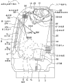
Fig. 1 means the integral body of drum-type washing drying machine 1 of embodiment involved in the present invention and the stereogram that comprises biopsy cavity marker devices of internal structure, Fig. 2 means the rearview that comprises biopsy cavity marker devices of the internal structure of drum-type washing drying machine shown in Figure 11, Fig. 3 means the right view that comprises biopsy cavity marker devices of the internal structure of drum-type washing drying machine shown in Figure 11, and Fig. 4 means the top view that comprises biopsy cavity marker devices of the internal structure of drum-type washing drying machine shown in Figure 11.
[summary of drum-type washing drying machine 1]
The drum-type washing drying machine 1 of embodiment (Fig. 1~Fig. 4) supply water and draining in cylinder 5 rotations, thus, wash putting into washings 14 (with reference to Fig. 3) in cylinder 5, rinsing and dehydration, then blow warm braw (50 (50A, 50B)) (with reference to Fig. 3) to washings 14 in cylinder 5 rotations and carry out drying, thereby carry out automatically and continuously washing, rinsing, dehydration and the drying of washings 14.
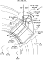
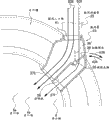
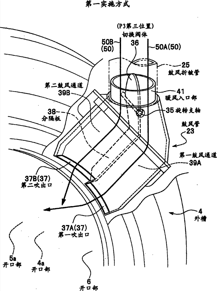
Fig. 5 is the switching action (with reference to arrow 40A, the 40B of Fig. 5, Fig. 7) that the structure of the blast pipe 23 by drum-type washing drying machine 1 and warm braw 50A, 50B that 36 pairs of switching valves blow to washings 14 carry out to Fig. 7, changes the stereogram of the first embodiment of the blow-off direction of warm braw 50A, 50B.
Be provided with switching valve 36 in the blast pipe 23 of Fig. 3 and drum-type washing drying machine 1 shown in Figure 4, this switching valve 36 can be supported on warm braw inlet portion 41 (with reference to Fig. 5~Fig. 7), this switching valve 36 forms the upstream side (diagram upside) mobile from 35 extensions of rotation fulcrum to warm braw 50A, 50B or the shape of heater 21 sides by rotary axis of earth.
As Fig. 5, shown in Figure 6, in the air channel of switching valve 36 from blast pipe 23 till the peristome 4a of water jacket 4, be formed with and be separated into the first blast channel 39A and the second blast channel 39B of two by demarcation strip 38, the first blast channel 39A be connected blast channel 39B respectively with towards the first blow-off outlet 37A of the inside opening of cylinder 5 be connected blow-off outlet 37B and be connected.
When dry operating, from the first and second blow-off outlet 37A, the 37B of blast pipe 23, washings 14 is blown warm braw 50 (50A, 50B) and carry out drying.
When dry operating, by making the switching valve 36 in blast pipe 23 carry out rotational action (with reference to arrow 40A, the 40B in Fig. 5, Fig. 7), switch the first blow-off outlet 37A and the second blow-off outlet 37B, come thus suitably to change wind direction, wind speed and the air quantity etc. of warm braw 50A, 50B.
Thus, can be used in wind direction or the variable area that dries up dry warm braw 50 (50A, 50B) to cylinder 5 inside thereby make the warm braw blow-off outlet (the first and second blow- off outlet 37A, 37B) of washings 14 dryings.
The below is elaborated to the structure of drum-type washing drying machine 1.
[drum-type washing drying machine 1 exterior]
Drum-type washing drying machine 1 shown in Figure 1 is on the top as the pedestal 3 of foundation support parts, fixes etc. that by screw the housing as support unit (not shown) that combined steel plate and synthetic resin consist of being installed.
On housing, be provided with the front surface cover c1 of the housing that consists of front surface and be used for picking and placeing the lid that can open and close 7 of washings 14 at its front surface, and being provided with the back side cover c2 of the housing that consists of the back side at the back side of housing.Consist of the housing of scrubbing-and-drying unit 1 by these front surface covers c1, back side cover c2 and pedestal 3 etc.
On the top of front surface cover c1, be provided with the guidance panel 51 for the operation of being carried out drum-type washing drying machine 1 by the user.
Be equipped with on guidance panel 51: the power switch of the on/off of the power supply of responsible drum-type washing drying machine 1; Be used for selection and wash a plurality of pushbutton switch 51s of each patterns such as the standard procedure of dry (washing dry continuous operation), washing, drying; And (not shown) such as beginning switches that be pressed when beginning each pattern.In addition, be equipped with the display 51h of light emitting diode on guidance panel 51, this display 51h has a plurality of demonstrations for the operating state of informing drum-type washing drying machine 1 to the user.
[water jacket 4]
Drum-type washing drying machine 1 shown in Figure 1, on pedestal 3 in the housings such as its front surface cover c1, be supported with the open water jacket cylindraceous 4 of front surface side by draft hitch (suspention) 2, and this water jacket 4 be supported to make its axle center as shown in Figure 3 before the level face side mode slightly up tilt.
The water jacket 4 following effects of performance: store washings when washing, rinsing process, receive the moisture of removing from washings 14 when dehydrating operation, and this moisture is discharged.
In addition, engaging has not shown draft helical spring on water jacket 4, thereby has prevented toppling over of water jacket 4.
Water jacket 4 with the lid 7 front surface side opposed position by peristome 4a (with reference to Fig. 1) and opening, and water jacket 4 forms the shape with very large diameter short cylinder shape that the inside with all side panel 4c cylindraceous (with reference to Fig. 2) and flat back veneer 4d is cavity.
When the past face side (the arrow A direction in Fig. 1) is observed drum-type washing drying machine 1 shown in Figure 1, dispose for the washing agent of putting into washing agent in water jacket 4 in the bight, upper left of water jacket 4 and put into section 10.In addition, description thereof is omitted to put into the details of structure of section 10 for washing agent.
[draft hitch 2]
The draft hitch 2 of supporting water jacket 4 grades constitutes and comprises the compression helical spring with elastic force and for example enclose have oil to produce the oil damper of damping force by the viscous drag of oil, in order to reduce the vibration of water jacket 4 when the running of drum-type washing drying machine 1.
[cylinder 5]
Dispose with the mode axle supporting ground that can rotate the cylinder 5 that makes the opening of front surface side by peristome 5a with one heart at the inboard of Fig. 2, water jacket 4 shown in Figure 3 and water jacket 4.
Cylinder 5 for example uses the very thin stainless-steel sheet of thickness of slab and forms the following shape with large diameter short cylinder shape: nearby side is passed through peristome 5a (with reference to Fig. 1, Fig. 3) and opening, and has cylindraceous all panel 5c and the flat back veneer 5d that consists of peripheral part.
The drive motor 8 of the back veneer 4d of cylinder 5 by being arranged at water jacket 4 back sides is being driven in rotation under directly driving.Cylinder 5 can certainly wait reducing gear to be driven by drive motor 8 through transmitting band in addition.
Here, run through being provided with a large amount of apertures (not shown) on cylindraceous all panel 5c of Fig. 2 and cylinder 5 shown in Figure 3 and flat back veneer 5d, the air stream the when moisture of removing from washings 14 when this aperture is used for making the centrifugal dehydration of dehydration procedure and drying process passes through.
In addition, in the inboard of cylinder 5, be provided with a plurality of tappets (lifter) (not shown), when these a plurality of tappets rotate in driven motor 8 drivings of cylinder 5, washings 14 is raised, the position of change washings 14, thus the effectively washing such as washing, dry etc. can be patted.
[lid 7]
As shown in Figure 1, the housing front surface side at drum-type washing drying machine 1 is formed with peristome 6, and is provided with and covers 7, and 7 pairs of these peristomes 6 of this lid, the peristome 4a of water jacket 4 and the peristome 5a of cylinder 5 etc. open and close.
Lid 7 for example is supported to and can opens and closes along arrow α 1 direction in Fig. 1 by axle, by pressing door open button (not shown), can be opened to the release position with label 7 ' (in Fig. 1 shown in dotted line) expression.
The user is by pressing door open button (not shown), to cover 7 be opened to label 7 ', washings 14 is put into the inside of cylinder 5 from peristome 6, then, closing cap 7, the peristome 4a of closed peristome 6, water jacket 4, the peristome 5a of cylinder 5 etc., wash, drying process after rinsing, dehydration, afterwards, by again pressing door open button, make cover 7 be opened to label 7 ', the dry complete washings 14 of washing is taken out.
[bellows 9]
The peristome 4a that the peristome 6 of the front surface side of drum-type washing drying machine 1 is connected with water jacket is by connecting such as the bellows 9 (bellows) that forms with flexible materials such as rubber.
And, when closing cap 7, the part of bellows 9 becomes and lid 7 position relationships that contact, thus, even water jacket 4 is in the situation that middle vibrations such as washing, rinsing, dehydration procedures, by the strain of bellows 9, prevented from the space occurring at bellows 9 with between covering 7, thereby made the sealing of water reliable.
On the other hand, the vibration of the water jacket 4 during about dehydration procedure etc., the internal friction by bellows 9 has absorbed transmits the vibration of the housing such as face cap c1 forward.
[drying unit 11]
In drum-type washing drying machine shown in Figure 11, in the past face side is observed (the arrow A direction in Fig. 1), disposes from the rear of water jacket 4 to the bight, upper right be used to the drying unit 11 that makes the washings that contains moisture 14 dryings after washing.
Drying unit 11 comprises: the dehumidification pipe 13 (with reference to Fig. 2, Fig. 3) that the moisture of absorption washings 14 dehumidifies to the high humid air of humidity; Be used for removing the filter 16 (with reference to Fig. 1, Fig. 4) as the fine hair of Soft flocks etc. of sending here together with above-mentioned air; Be used in the fan 18 (with reference to Fig. 1, Fig. 2) that dry air circulates; Heat to form the heater 21 as heating unit (with reference to Fig. 1, Fig. 3) of warm braw 50 to being used for dry air; And connect connection air channel 24 (with reference to Fig. 1, Fig. 2) that dehumidification pipe 13 is connected with fan.
In addition, heater 21 is so-called encapsulation heater (sheath Heater), in the situation that form the structure of not worrying by foreign matters from being blockeds such as fine hair, also can there is no filter 16.
[dehumidification pipe 13 of drying unit 11]
Closely be provided with dehumidification pipe 13 (with reference to Fig. 2) with water jacket 4 shown in Figure 1, this dehumidification pipe 13 through wrinkle pipe 15 (with reference to Fig. 3) with the exhaust outlet 12 of the back veneer 4d bottom that is arranged at water jacket shown in Figure 24 back sides, the exhaust outlet 12 that namely is arranged at water jacket 4 bottoms is connected, and this dehumidification pipe 13 extends towards the top, and connects with the air channel 24 (with reference to Fig. 2) that is connected that is connected in fan 18.Like this, connect by telescopic wrinkle pipe 15 (with reference to Fig. 3) between water jacket 4 and dehumidification pipe 13.
Dehumidification pipe 13 has the Dehumidifying elements such as heat exchanger (not shown), the humid air that will contain from cylinder shown in Figure 35 inner moist washings 14 and absorb the moisture that comes is discharged to arrow 30 directions from the exhaust outlet 12 of being located at water jacket 4 lower backside like that as shown in Figure 2 and Figure 3 and is transported to the process of top from the below along back veneer 4d (with reference to Fig. 2) outside of water jacket 4, this Dehumidifying element for example flows through cooling water, make by cooling humid air of discharging the hydrogenesis that wherein contains, thereby dehumidify.
The connection of the drying unit 11 [air channel 24]
As shown in Figure 1 and Figure 2, dehumidification pipe 13 the back upper place of water jacket 4 be connected air channel 24 and connect, (with reference to Fig. 1) roughly forwards extended along the rotating shaft of cylinder 5 in this connection air channel 24 from the rear.The air of sending from dehumidification pipe 13 that dehumidifies by Dehumidifying element is connecting the interior direction conveying to arrow 31 (with reference to Fig. 1) in air channel 24.
[filter 16 of drying unit 11]
As shown in Figure 1, connect air channel 24 and be connected with filter 16, capture as the fine hair that makes the Soft flocks that contain in the air of washings 14 dryings by this filter 16.
Filter 16 is arranged to the user and can be plugged from the front surface side (the arrow A direction Fig. 1) of drum-type washing drying machine 1, and is clean thereby the user can extract filter 16 the fine hair cleaning that traps.In addition, description thereof is omitted for the details of the structure of this filter 16.
In addition, heater 21 is so-called encapsulation heaters, in the situation that form the structure of not worrying by foreign matters from being blockeds such as fine hair, also can there is no filter 16.
[fan 18 of drying unit 11]
As Fig. 1, shown in Figure 3, carried out in filter 16 air that fine hair captures along the direction of arrow 32 by communicating passage and be directed to the rotating center section of the rotating vane of the inside of being located at fan 18, this communicating passage and filter 16 be adjacent to arrange and and water jacket 4 between have the space, and will and fan 18 between couple together.
Fan 18 is so-calledly to have the Sirocco fan (siroccofan) of centrifugal a plurality of small-sized forward curved vanes or have the turbofan (turbofan) of backward leaning vane, rotating vane rotates by fan drive motor 20, utilizes centrifugal force that air is accelerated.
Air after accelerating by fan 18 is heated the warm braw 50 that becomes drying by heater 21 (with reference to Fig. 3, Fig. 4) time, then be blown into the inside (warm braw 50 (50A, 50B)) of cylinder 5 via air blast wrinkle pipe 25 (with reference to Fig. 3) along the direction shown in arrow 34A or 34B from the blast pipe 23 to the front surface opening of water jacket 4.In addition, for the unit that is blown into direction that changes warm braw 50, will narrate in the back.
Thereby heating, the 50 pairs of washings 14 of warm braw that are blown into the inside of cylinder 5 make the moisture evaporation become humid air, then be drawn into from exhaust outlet shown in Figure 2 12 dehumidification pipe 13 of outside of water jacket 4, thereby and then from dehumidification pipe 13 by dehumidified as previously mentioned.
By repeatedly carrying out continuously dry cycle as described above, the moist washings such as clothing 14 are dried.
[blast pipe 23]
Next use Fig. 5 to Figure 12, the structure of blast pipe involved in the present invention 23 to be described.
Fig. 5 means the stereogram of the switching action of the structure of blast pipe 23 and 36 pairs of warm braws 50 of switching valve described later to Figure 10, Fig. 5 represents to change warm braw from the first embodiment of the blow-off direction of blast pipe 23 to Fig. 7.
In structure shown in Figure 7, the direction that the warm braw 50A that blows out from the first blow-off outlet 37A shown in Figure 5 blows to cylinder 5 inside is such direction at Fig. 5 of the first embodiment: near the central authorities or central authorities of the inboard of the cylinder 5 of arrow 34A direction shown in Figure 3.On the other hand, the direction that the warm braw 50B that blows out from the second blow-off outlet 37B shown in Figure 7 blows to cylinder 5 inside is such direction: near the lower surface or lower surface of the cylinder 5 of arrow 34B direction shown in Figure 3, the first and second blow- off outlet 37A, 37B are configured to the blow-off direction different (with reference to Fig. 6) of separately warm braw 50A, 50B.
Fig. 8 represents to change the air quantity of warm braw 50 to Figure 10 the second embodiment of structure is used as another example of blast pipe 23.
At Fig. 8 of the second embodiment in structure shown in Figure 10, the area of the area of the first blow-off outlet 37C and the second blow-off outlet 37D is different, for example, the area of the first blow-off outlet 37C is less, and the area of the second blow-off outlet 37D is larger, the direction that warm braw 50A, the 50B that blows out from the first and second blow- off outlet 37C, 37D blows to cylinder 5 inside is equidirectional, is towards the central authorities of the inboard of the cylinder 5 of arrow 34A direction shown in Figure 3 or near the direction (with reference to Fig. 9) central authorities.
As shown in Fig. 8,9 of Fig. 5 of the first embodiment, the 6 and second embodiment, in blast pipe 23, be provided with switching valve 36, this switching valve 36 is supported to and can rotates around rotation fulcrum 35 by axle, this rotation fulcrum 35 with the flow direction of edge and warm braw 50 (50A, 50B) roughly the mode in the direction transversal air channel of quadrature be arranged at warm braw inlet portion 41.
Namely, as Fig. 9 of Fig. 6, Fig. 7 of the first embodiment and the second embodiment, shown in Figure 10, with respect to warm braw inlet portion 41, the downstream (diagram downside) of flowing at warm braw 50 disposes rotation fulcrum 35, on the other hand, switching valve 36 is configured to the shape that the upstream side (diagram upside) that flows to warm braw 50 with respect to warm braw inlet portion 41 from rotation fulcrum 35 or heater 21 sides are extended.
Like this, the shape of extending by upstream sides (diagram upside) from rotation fulcrum 35 to warm braw 50 that switching valve 36 is configured to flow from or heater 21 sides, as Fig. 5, shown in Figure 7, at primary importance P1 (with reference to Fig. 5), second place P2 (with reference to Fig. 7), blast by warm braw 50 (50A, 50B), switching valve 36 is compressed against on the inner surface of warm braw inlet portion 41, thereby can carry out reliably the switching action of switching valve 36.
On the other hand, inverted configuration with present embodiment, in the situation that with switching valve 36 is configured to from rotation fulcrum 35 to downstreams (diagram downside) that warm braw 50 flows or heater 21 opposition sides extend shape, blast by warm braw 50, switching valve 36 opens wide air flow channel, that is, switching valve 36 is pressed into from the inner surface of warm braw inlet portion 41 and leaves, thereby the switching action of switching valve 36 becomes unstable.
Shown in Figure 5 as the first embodiment, from the downstream of switching valve 36 to the first and second blow- off outlet 37A, 37B till, separate and the first blast channel 39A and the second blast channel 39B that separate each other are set up in parallel by demarcation strip 38.
That is, as Fig. 5, shown in Figure 8, the first blast channel 39A is connected with the first blow-off outlet 37A, and the second blast channel 39B is connected with the second blow-off outlet 37B.
The first blow-off outlet 37A, the second blow-off outlet 37B cylinder 5 inside in water jacket (4) respectively are opened near the peristome 5a of cylinder 5, when dry operating, the first blow-off outlet 37A and the second blow-off outlet 37B carry out drying with the washings 14 that warm braw 50 (50A, 50B) blows in cylinder 5.
One end of demarcation strip 38 and the rotation fulcrum 35 of switching valve 36 configure in contact, in the part that contacts with each other, will be held in airtight construction between demarcation strip 38 and switching valve 36 thereby be provided with such as the seal that is made of flexible member may such as rubber.
In Fig. 8 of Fig. 5 of the first embodiment and the second embodiment, illustrate the primary importance P1 that switching valve 36 is got to the rotation of arrow 40A direction, around switching valve 36 or the part that contacts with switching valve 36 of the inner peripheral surface of warm braw inlet portion 41 be provided with such as the seal that is consisted of by flexible member may such as rubber (not shown), in order to will seal between switching valve 36 and warm braw inlet portion 41, thereby will be held in airtight construction between the inner peripheral surface of warm braw inlet portion 41 and switching valve 36.
Thus, shown in Figure 8 as Fig. 5 of the first embodiment and the second embodiment, pass through blast pipe 25 (with reference to Fig. 3) warm braw 50A and only be directed to the first blast channel 39A that is separated by switching valve 36 and demarcation strip 38 at warm braw inlet portion 41, then be blown out to cylinder 5 inside from the first blow-off outlet 37A (37C).On the other hand, the the second blast channel 39B that is connected with the second blow-off outlet 37B is by switching valve 36 and demarcation strip 38 and through seal (not shown) sealing (with reference to Fig. 5, Fig. 8), therefore, warm braw 50A can not enter this second blast channel 39B, and warm braw 50A can not blow out from the second blow-off outlet 37B.
In Figure 10 of Fig. 7 of the first embodiment and the second embodiment, respectively expression make switching valve 36 to arrow 40B direction rotate and second place P2.To remain airtight construction between the inner peripheral surface of warm braw inlet portion 41 and switching valve 36 by not shown seal between the inner peripheral surface of switching valve 36 and warm braw inlet portion 41.
Thus, warm braw 50B such as the Fig. 7, shown in Figure 10 of blast pipe 25 (with reference to Fig. 3) have been passed through, only be directed to the second blast channel 39B that is separated by switching valve 36 and demarcation strip 38 at warm braw inlet portion 41, and be blown out to cylinder 5 inside from the second blow-off outlet 37B (37D).On the other hand, the the first blast channel 39A that is connected with the first blow-off outlet 37A (37C) seals through seal (not shown) by switching valve 36 and demarcation strip 38, therefore warm braw 50B can not import to the first blast channel 39A, and warm braw 50B can not blow out from the first blow-off outlet 37A (37C).
Fig. 6 of the first embodiment represents the 3rd position P3, and the 3rd position P3 is the centre position between the second place P2 of the primary importance P1 of switching valve shown in Figure 5 36 and switching valve 36 shown in Figure 7.Similarly, Fig. 9 of the second embodiment represents the 3rd position P3, and the 3rd position P3 is the centre position between the second place P2 of the primary importance P1 of switching valve shown in Figure 8 36 and switching valve 36 shown in Figure 10.
The switching valve 36 at the 3rd P3 place, position shown in Figure 9 of Fig. 6 of the first embodiment, the second embodiment does not contact with the inner peripheral surface of warm braw inlet portion 41.
Under the state shown in Figure 9 of Fig. 6 of the first embodiment, the second embodiment, when being blown into warm braw 50 from blast pipe 25 to warm braw inlet portion 41, a part of warm braw 50A of warm braw 50 is imported into the first blast channel 39A, then be blown out to cylinder 5 inside from the first blow-off outlet 37A (37C), another part 50B of warm braw 50 is imported into the second blast channel 39B, then is blown out to cylinder 5 inside from the second blow-off outlet 37B (37D).
Here, in the structure of Figure 10, make the area of the first blow-off outlet 37C and the second blow-off outlet 37D different at Fig. 8 of the second embodiment, for example make the area of the first blow-off outlet 37C less, make the area of the second blow-off outlet 37D larger.
As shown in Figure 8, primary importance P1 at switching valve 36, when blowing out warm braw 50A from the first blow-off outlet 37C, because the fluid resistance of blow-off outlet is large, so flow velocity is large but air quantity is little, as shown in figure 10, at the second place P2 of switching valve 36, when blowing out warm braw 50B from the second blow-off outlet 37D, the fluid resistance of blow-off outlet is little, therefore flow velocity is little, but air quantity is large.
In addition, at the 3rd position P3 shown in Figure 9 of the second embodiment, owing to blowing out warm braw 50A, 50B from the first blow-off outlet 37C and the second blow-off outlet 37D, therefore, the fluid resistance of blow-off outlet is minimum, so the air quantity of warm braw 50A, 50B is maximum.
Like this, in the second embodiment, by as Fig. 8, Figure 10, change as shown in Figure 9 the area of blow-off outlet, can change air quantity and the wind speed of warm braw 50.
Here, at the primary importance P1 shown in Figure 8 of the second embodiment, the speed of establishing the warm braw 50A that blows out from the first little blow-off outlet 37C of area is the speed of for example 100m (rice)/more than s (second), and air quantity is 1.4m
3(cubic meter)/minute more than, can launch by the blast of warm braw 50A the fold of the washings 14 such as clothing, can make quality good.
In addition, in case be that the washings 14 such as clothing is in the situation that dry with fold, even after this blow warm braw 50 to the washings such as clothing 14 at high speed, fold is not unfolded yet, therefore, in order to make quality good, also need also to blow constantly warm braw 50A at a high speed until dry complete very moist state from the washings such as clothing 14.
On the other hand, at second place P2 shown in Figure 10, when blowing out warm braw 50 from the second large blow-off outlet 37D of area, perhaps when the 3rd position P3 shown in Figure 9 blows out warm braw 50 from the first blow-off outlet 37C and the second blow-off outlet 37D, wind speed for example can be reduced to 20m/s, but air quantity can increase to 2m
3/ more than dividing.Perhaps, if the air quantity of warm minute 50 keeps 1.4m
3/ divide to get final product, even further reduce the rotary speed of fan 18, also can obtain the air quantity of warm braw 50, therefore, can reduce the power that is applied to fan drive motor 20 (with reference to Fig. 1), can realize the low consumption electrification, have energy-conservation effect.
[driving mechanism of switching valve 36]
Next, one example of the driving mechanism of the switching valve 36 of Fig. 5~shown in Figure 10 is described to Figure 12 by Figure 11.
Figure 11 observes the stereogram of an example of driving mechanism of the expression switching valve 36 of blast pipe 23 from the direction opposite with the blast pipe shown in Figure 8 23 of Fig. 5 of the first embodiment and the second embodiment (Fig. 5, shown in Figure 8 B direction).Figure 12 observes the stereogram of an example of driving mechanism of the expression switching valve 36 of blast pipe 23 from the direction opposite with Fig. 7 and Figure 10 (Fig. 7, shown in Figure 10 C direction).
As Figure 11, shown in Figure 12, being fixed with on the rotation fulcrum 35 of switching valve 36, be fixed with cursor 42, when making cursor 42 rotation, switching valve 36 is through 35 rotations of rotation fulcrum.
With respect to one of cursor 42 distolateral rotation fulcrum 35, at another distolateral fulcrum 43 that is provided with of cursor 42, be connected with rotationally an end of connecting rod 44 on this fulcrum 43, cursor 42 links rotationally through the end of fulcrum 43 with connecting rod 44.
And the other end of connecting rod 44 is connected in fulcrum 46 rotationally, and this fulcrum 46 is arranged at an end of the actuating arm 47 that is driven by transfer valve motor 45, and the other end of connecting rod 44 is connected with actuating arm 47 rotationally through this fulcrum 46.
Transfer valve motor 45 has the reducing gear (not shown) of predetermined speed reducing ratio, and the High Rotation Speed of the motor reel of transfer valve motor 45 is decelerated to the matched speed of low speed action with switching valve 36.
Under state shown in Figure 11, switching valve 36 rotates significantly and is in primary importance P1 (top dead-centre) (with reference to Fig. 5, Fig. 8) to arrow 40A direction, contact with switching valve 36 by the inner peripheral surface that makes warm braw inlet portion 41, keep airtight construction through not shown seal.
Under state shown in Figure 12, switching valve 36 significantly rotates and is in second place P2 (bottom dead centre) (with reference to Fig. 7, Figure 10) to arrow 40B direction, contact with switching valve 36 by the inner peripheral surface that makes warm braw inlet portion 41, keep airtight construction through not shown seal.
Namely, by making 45 reciprocating motions of transfer valve motor, switching valve 36 is moved between top dead-centre (primary importance P1) (with reference to Figure 11) and bottom dead centre (second place P2) (with reference to Figure 12), thereby switch the first blow-off outlet 37A (37C) (with reference to Figure 11) and the second blow-off outlet 37B (37D) (with reference to Figure 12).
In addition, also be provided with: the first detecting unit 48, it detects the situation that switching valve shown in Figure 11 36 is positioned at upper dead center position (primary importance P1) (with reference to Fig. 5, Fig. 8); And second detecting unit 49, it detects the situation that switching valve shown in Figure 12 36 is positioned at lower dead point position (second place P2) (with reference to Fig. 7, Figure 10).
These first detecting units 48 and the second detecting unit 49 can be the microswitches that for example detects the position of actuating arm 47, can be perhaps the Hall IC that the magnet that is arranged at actuating arm 47 is detected, can be also perhaps the light-emitting component of the photo-coupler that detects of the situation to a part of shading of actuating arm 47 and a pair of element that photo detector forms.
In addition, the one the second detecting units 48,49 can also detect switching valve 36 driving mechanisms except actuating arm 47 or the motion of switching valve 36.
In addition, it can be also the approach switch that the actions of the action of the driving mechanism of the actuating arm 47 that comprises switching valve 36 or switching valve 36 itself is detected in non-contacting mode, be positioned at upper dead center position (primary importance P1) or lower dead point position (second place P2) as long as can detect switching valve 36, the structure of the first detecting unit 48 and the second detecting unit 49 can suitably be selected.
[control system]
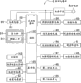
Figure 13 means the block diagram of structure of the control system of index drum formula scrubbing-and-drying unit 1.
On guidance panel shown in Figure 1 51, as mentioned above, the various switch 51s that are provided with the display 51h that comprises various demonstrations and comprise power supply, these displays 51h, various card close 51s and are connected with display part, the key input part of shown in Figure 13 function circuit section 94 respectively.
Switch 51s be used for to select the execution of washing, rinsing, dehydration, dry each operation etc., the display 51h that comprises various demonstrations be used for showing detergent amount, the water yield or various operations time, carry out state, abnormal etc.
The control circuit S of section shown in Figure 13 consists of centered by the microcomputer 100 (hereinafter referred to as microcomputer) that is arranged at main control substrate 52.This control circuit S of section plays a role as the control module of the overall operation of index drum formula scrubbing-and-drying unit 1.
The operation signal of the various switch 51s that comprise power switch of guidance panel 51 shown in Figure 1 is imported in microcomputer 100, on the other hand, microcomputer 100 will operate switch (51s) with the user and the operation signal that produces turn round accordingly setting value, need detergent amount, the water yield or various operations time, carry out state, the information output such as abnormal to the display 51h that comprises various demonstrations, buzzer (not shown), control the water supply and sewage control circuit 96 of the various actuators such as water supply and sewage valve 93 etc.
95 pairs of source power supplies of power circuit directly carry out rectification makes it level and smooth, to supply with needed dc source to microcomputer 100 or other circuit.Therefore, the dc source of microcomputer 100 or other circuit becomes the form overlapping with commercial ac power source.
And, microcomputer 100 is according to the input signal such as the operation signal of various switch 51s, the detection signal of humidity sensor 90 and be stored in the control program of describing with C language etc. in ROM (Read Only Memory), controls each motor such as water supply and sewage valve 93 each motor-driven valves such as grade, fan drive motor 20 etc.
Specifically, microcomputer 100 utilizes source power supply to switch on through 96 pairs of various water supply and sewage valves 93 of water supply and sewage control circuit, comes the switching of control valve.In addition, microcomputer 100 is controlled the rotation of fan drive motor 20 through air-supply control circuit 98, thereby makes from the air quantity of blast pipe 23 (with reference to Fig. 3) variable.
In addition, microcomputer 100 is controlled direction of rotation, the rotary speed of the drive motors such as brushless motor 8 of head roll 5 (with reference to Fig. 3) rotation through motor drive circuit 99.If it is large that the rotary load torque of drive motor 8 becomes, motor drive circuit 99 increases put on the electric current of drive motor 8 so that the driving torque increase, on the other hand, if the rotary load torque of drive motor 8 diminishes, motor drive circuit 99 reduces to put on the electric current of drive motor 8, so that driving torque reduces, thus, motor drive circuit 99 makes rotary speed keep constant control.
In motor drive circuit 99, can put on the electric current of drive motor 8 by detection, judge the size of the load torque that acts on drive motor 8, thereby detect the cloth amount of putting into cylinder 5 inside.
Like this, the detection of the cloth amount of washings 14 can be by carrying out according to the electric current of drive motor 8 and the rotating torques of rotary speed detection drive motor 8.These structures that detect the cloth amount of washings 14 are called the cloth amount detection unit.
Detergent amount operational part 101 calculates the required detergent amount of washing according to the cloth amount that detects.
90 pairs of temperature and humidities that are used for the warm braw 50 (50A, 50B) of cloth drying of temperature sensor 92 and humidity sensor detect, and this detection signal is sent to main control substrate 52.
Comparing section 102 compares the measured value (detection signal) of temperature sensor 92 and humidity sensor 90 and pre-stored a reference value 103, and 100 outputs are large or little with respect to a reference value 103 to microcomputer.In addition, microcomputer 100 is controlled direction of rotation, rotating speed of transfer valve motor 45 (with reference to Figure 11, Figure 12) etc. through transfer valve control circuit 97, thereby makes the position changeable of switching valve 36.
Upper dead center position (primary importance P1) (with reference to Fig. 5, Fig. 8, Figure 11) or the lower dead point position (second place P2) (with reference to Fig. 7, Figure 10, Figure 12) of the first detecting unit 48 and 49 pairs of switching valves 36 of the second detecting unit detect, and detection signal is sent to microcomputer 100.
[action of drum-type washing drying machine 1]
Next the action of drum-type washing drying machine shown in Figure 11 described.
At first, the summary operation of the washing drying in drum-type washing drying machine 1 is described.
Figure 14 means the figure of general flowchart of the standard procedure of drum-type washing drying machine 1.
At first, the user presses the power switch of guidance panel shown in Figure 1 51, and standard procedure switch 51s is connected, and at this moment, begins to carry out the action of standard procedure, carries out successively the washing of washings 14, twice middle dehydration post rinse, final dewatering and drying.
With reference to Figure 14, at first, the power switch of user's push panel 51 (with reference to Fig. 1) switches on power, connects standard procedure switch 51s, and at this moment, the cloth amount of carrying out washings 14 detects (step 1).And afterwards, the user puts into washing agent (step 20).
Carrying out necessary water pipe water supply (step 2) afterwards, wash (step 3), washings are carried out draining (step 4).Afterwards, for contained washing agent in the washings 14 of back-outing, carry out middle dehydration (step 5) for the first time, in order then to carry out rinsing for the first time, water supply start (step 6).
After primary rinsing (step 7) finishes, carry out the draining (step 8) of these washings.After this, for the washing agent that also contains in the washings 14 of back-outing, carry out secondary middle dehydration (step 9), in order to carry out secondary rinsing water supply start (step 10).
After secondary rinsing (step 11) finishes, these washings are carried out draining (step 12), then carry out final dewatering (step 13).
At last, carry out drying (step 14), thereby finish washing and dry.
[action control 1 of switching valve 36]
Next, an example of the action control (with reference to Fig. 5, Fig. 6, Fig. 7) of the switching valve 36 in drying process (step 14 of Figure 14) described.
As an example, how many judgements of cloth amount that detect according to the cloth amount based on washings 14 are described, carry out the example that wind direction is controlled.
in general flowchart shown in Figure 14, carried out the cloth amount at the cloth amount detection unit by washings 14 and detected (step 1) afterwards, in the amount that consequently is judged as washings 14 in the situation that below 3kg, the cloth amount is thought on a small quantity, in the step 14 of Figure 14, as shown in Figure 7, mobile switching valve 36 blows out warm braw 50B from the second blow-off outlet 37B, arrow 34B as shown in Figure 3 makes the wind direction of warm braw 50B like that near the lower surface or lower surface of cylinder 5, thus, concentrate near the state the lower surface of cylinder 5 for a small amount of washings 14, can make expeditiously warm braw 50B blow near a small amount of washings 14 of lower surface of cylinder 5.
On the other hand, detect (step 1 of Figure 14) afterwards in the cloth amount of having carried out washings 14, surpassed 3kg in the situation that consequently be judged as the amount of washings 14, the amount of washings 14 is more, and washings 14 is full of the inside of cylinder 5.
Therefore, in the step 14 of Figure 14, as shown in Figure 5, mobile switching valve 36 blows out warm braw 50A from the first blow-off outlet 37A, shown in the direction of arrow 34A as shown in Figure 3, the blow-off direction that makes warm braw 50A be wind direction near the central authorities or central authorities of cylinder 5, make thus warm braw 50A blow to the central authorities of washings 14.
Like this, by the suitable wind direction of how much selecting corresponding to the amount of washings 14, thus, can effectively promote moisture from washings 14 evaporations, thereby can improve drying efficiency.
[action control 2 of switching valve 36]
As other embodiment, the example that first half term and the second half at drying process (step 14 of Figure 14) are changed air quantity or wind speed describes.
Under the state that final dewatering operation (step 13) shown in Figure 14 is completed, washings 14 is in wet well-proportioned state in the inside of cylinder 5, therefore, first half term in drying process (step 14 of Figure 14), in order to promote moisture from wet that well-proportioned washings 14 evaporates, preferably make warm braw 50 blow to washings 14 integral body by increasing air quantity, to promote moisture from washings 14 evaporations.
but, from blow-off outlet 37 (37A, 37B, 37C, 37D) (with reference to Fig. 5, Fig. 8) near the washings 14 of the nearby side the peristome 5a of very near cylinder 5 is due to the warm braw 50 (50A that directly are dried, 50B) (with reference to Fig. 5, Fig. 8) blow to, therefore easily dry, on the contrary, the warm braw 50 of the washings 14 by being in cylinder 5 inboards (the paper right side of Fig. 3) has passed through nearby between the washings 14 of the humidity of side (the paper left side of Fig. 3), humidity uprises, and be used for making the latent heat of moisture evaporation to be seized, the temperature step-down, therefore, moisture is not easy evaporation.
Therefore, the second half at drying process, become following washings 14 and produced the even state of uneven drying: the washings 14 of the nearby side of cylinder 5 (left side of cylinder 5 shown in Figure 3) is drying, but the washings of cylinder 5 inboards (right side of cylinder 5 shown in Figure 3) 14 or humidity.
Like this, in order to make washings 14 dryings that produced the even state of uneven drying, need to be blown into warm braw 50, make warm braw 50 pass through the nearby washings 14 of side (left side of cylinder 5 shown in Figure 3), and arrive or the washings 14 of moist cylinder 5 inboards (right side of cylinder 5 shown in Figure 3).
For this reason, preferably, restriction blows out the area of outlet (blow-off outlet 37) of warm braw 50 (50A, 50B) (with reference to Fig. 5, Fig. 8), make the speed of blowing out at a high speed to improve pressure, make warm braw 50 blow to fiercely washings 14.
Namely, preferred such structure: in the first half term of drying process, for example the second embodiment is shown in Figure 10, the second blow-off outlet 37D large from area is blown into a large amount of warm braw 50B in cylinder 5, promote the drying that washings (14) is whole, in the second half of drying process, for example the second embodiment is shown in Figure 8, the first blow-off outlet 37C little from area is blown into warm braw 50A fiercely, so that inboard washings 14 dryings.
Perhaps, also can be in the first half term of drying process, shown in Figure 9 as the second embodiment blows out warm braw 50 (50A, 50B) in large quantities from the first blow-off outlet 37C and two blow-off outlets of the second blow-off outlet 37D.
As an example of the switching of the one the second blow-off outlet 37C, the 37D of the first half term that is used for carrying out such drying process and the second half, in the switching of carrying out the one the second blow- off outlet 37C, 37D from drying process begins after through the scheduled time.
About this scheduled time, detect the testing result of (step 1 of Figure 14) according to the cloth amount of washings 14, in the situation that the amount of washings 14 is many, because the time consumption of drying must be long, therefore, this scheduled time is also long, in the situation that the amount of washings 14 is few, because the time of drying is very short, therefore should set the scheduled time shortlyer, can make according to the amount of washings 14 like this warm braw 50 air quantity switching time just in time.
Perhaps, also can carry out according to the hygrometry result of being measured by humidity sensor 90 (with reference to Figure 13) switching of the one the second blow- off outlet 37C, 37D.
Namely, preferred such structure: in the situation that from beginning is dry humidity more than predetermined value, shown in Figure 10 as the second embodiment, the second blow-off outlet 37D large from area is blown into a large amount of warm braw 50B, be dried and make humidity reduce gradually and reach below predetermined value in the situation that arrived the second half, the washings 14 of drying process, for example the second embodiment is shown in Figure 8, and the first blow-off outlet 37C little from area blows out warm braw 50A fiercely.
Perhaps, also can be in the first half term of drying process in the situation that humidity also more than predetermined value, shown in Figure 9 as the second embodiment blows out warm braw 50 (50A, 50B) in large quantities from the first blow-off outlet 37C and two blow-off outlets of the second blow-off outlet 37D.
[action control 3 of switching valve 36]
In addition, as other example, following example is described: can select the preferential pattern of dry mass and the preferential pattern of drying efficiency, blow out suitable warm braw 50 according to selected pattern.
That crosses as previously explained is such, when from washings 14 also very moist state to the area of the complete restriction warm braw of drying blow-off outlet (the one the second blow- off outlet 37C, 37D (with reference to Fig. 8)) and when continuing to blow out at a high speed warm braw 50, utilize the blast of warm braw 50, fold is unfolded, and quality is good.
On the other hand, when the area that enlarges warm braw blow-off outlet (the one the second blow- off outlet 37C, 37D (with reference to Fig. 8)) and when continuing to blow out a large amount of warm braws 50, promoted the evaporation of moisture, drying efficiency is improved, therefore, can shorten drying time and save energy, if further reduce the rotary speed of fan 18 (with reference to Fig. 1), can be more energy-conservation.
Here, be provided with selection take good quality as preferential high quality mode with take shortening drying time and energy-conservation drying mode selected cell as preferential high efficiency mode on guidance panel 51, for example be provided with for any the pushbutton switch 51s that selects high quality mode and high efficiency mode, pushbutton switch 51s is connected with the key input part (with reference to Figure 13) of function circuit section 94.And, if when having selected high quality mode, in drying process, shown in Figure 8 as the second embodiment, the first blow-off outlet 37C little from area blows out warm braw 50A fiercely, when having selected high efficiency mode, in drying process, shown in Figure 10 as the second embodiment, the second blow-off outlet 37D large from area blows out warm braw in large quantities, can blow out suitable warm braw 50 according to selected pattern, therefore, very preferably.
In the situation that selected high efficiency mode, also can be as the second embodiment shown in Figure 9, blow out a large amount of warm braw 50A, 50B from the first blow-off outlet 37C and two blow-off outlets of the second blow-off outlet 37D.
in addition, Fig. 5 about above-mentioned embodiment, the first blow-off outlet 37A shown in Figure 8, 37C and the second blow- off outlet 37B, 37D, in the first embodiment that reference Fig. 5 illustrated to Fig. 7, separately direction is different in the first blow-off outlet 37A and the second blow-off outlet 37B, make change of the wind, and in the second embodiment that reference Fig. 8 illustrated to Figure 10, the first blow-off outlet 37C is different with the second blow-off outlet 37D area separately, air quantity is changed, but about the first blow- off outlet 37A, 37C and the second blow- off outlet 37B, 37D, also can make area and direction neither same, air quantity and wind direction are changed together.
[mode of texturing of the second embodiment of the air quantity of change warm braw 50 (50A, 50B)]
Next, by Figure 15, Fig. 8 of the air quantity that changes warm braw 50 is described to other modes of texturing of the second embodiment shown in Figure 10.
In addition, Figure 15 is that face side (the arrow A direction of Fig. 1) is observed near the stereogram that comprises the major part cutaway view of blast pipe 23 of the mode of texturing of the second embodiment in the past.
The first blow-off outlet 37E is the little blow-off outlet that can blow out at high speed warm braw of area, when different from Fig. 8 of the second embodiment, switching valve 36 is (label 36 that represents with double dot dash line in reference to Figure 15 ') when having rotated to arrow 40A direction, and switching valve 36 is in and the internal perisporium of warm braw inlet portion 41 position relationship of butt not.
In Figure 15 of mode of texturing, when switching valve 36 has been rotated to the direction of arrow 40B (label 36 that represents with solid line in reference to Figure 15), warm braw 50 only is directed in the first blow-off outlet 37E by switching valve 36 and demarcation strip 38, and is blown at high speed the inside of cylinder 5.
On the other hand, switching valve 36 rotates and when being in the position of label 36 ' (representing with double dot dash line) in Figure 15 to the direction of arrow 40A, warm braw 50E, 50F are the same with Fig. 9 of the second embodiment, flow through the both sides of switching valve 36 and the both sides of demarcation strip 38 and blow out from the first blow-off outlet 37E and the second blow-off outlet 37F.In addition, in Figure 15 of mode of texturing, can not realize the mode that warm braw 50 only blows out from the second blow-off outlet 37F.
Here, about the warm braw 50E that blows out from the first blow-off outlet 37E, if be suitable for blowing out warm braw 50, blow-off outlet small size of the high speed corresponding with above-mentioned high quality mode, when making switching valve 36 arrive the position of label 36 ' (representing with double dot dash line) to the direction rotation of arrow 40A in Figure 15, the blow-off outlet that adds up to from the area with the first blow-off outlet 37E and the second blow-off outlet 37F blows out warm braw 50E, 50F, therefore can increase air quantity.
In addition, in the above-described embodiment, rotate about making switching valve 36, the situation of application transfer valve motor 45 (with reference to Figure 13) has been described, but also can have replaced motor with solenoid.
[action effect]
According to said structure, when drying, be blown into warm braw 50 from the blow-off outlet 37 (37A, 37B, 37C, 37D) of the front surface side of cylinder 5, therefore, warm braw 50 free space of face side in the past directly blows to the washings 14 such as clothing, warm braw 50 is by the inside of washings 14 and from exhaust outlet 12 discharges, so drying efficiency improves.
In addition, in order to improve the dry mass of the washings 14 such as clothing, diminish with more than wind speed is brought up to predetermined speed by the area that makes the blow-off outlet 50 that is blown into warm braw 50, the fold of the washings 14 such as clothing is launched, can improve thus dry quality.
therefore, in this drum-type washing drying machine 1, what change to be used for blowing out to cylinder 5 inside warm braw 50 when dry operating blows out mouth (the one the second blow-off outlet 37C, D etc.) aperture area, drying mode that can be preferential to quality (with reference to Fig. 8) and the drying mode that improved drying efficiency are (with reference to Fig. 9, Figure 10) switch, the preferential drying mode of described quality increases the speed of warm braw 50 by dwindling the area constraints air channel that blows out mouth, thereby be suitable for making the fold of the washings 14 such as clothing to trail, the area that the drying mode of described raising drying efficiency blows out mouth by increase increases the air quantity of warm braw 50, thereby improved drying efficiency.
in addition, about be blown into the direction of warm braw 50 to cylinder 5 inside, according to what of washings 14, for example many in washings 14 amounts, when washings 14 is filled cylinder 5 inside, make warm braw 50 towards the center of cylinder 5 (near central authorities or central authorities) (with reference to Fig. 5, Fig. 3), on the other hand, in the situation that washings 14 amounts are piled up near the lower surface of cylinder 5 less and only, make warm braw 50 near the lower surface of cylinder 5 or lower surface to blowing down (with reference to Fig. 7, Fig. 3), blow-off direction by such change warm braw 50, by warm braw 50 directly being blowed to the washings 14 such as clothing, can further improve drying efficiency.
Namely, by switching valve 36 is rotated, can be in the blow-off outlet direction that changes warm braw 50 midway of drying process, blow-off direction (with reference to Fig. 5, Fig. 7) when change blows out from warm braw 50 to cylinder 5 inside, therefore, can select the blow-off direction that is fit to according to the kind of the washings such as clothing 14 or amount, thereby improve drying efficiency.
In addition, in order to change the air quantity of warm braw 50, the mouth area (the one the second blow- off outlet 37C, 37D (with reference to Fig. 8) such as areas) that changes blow-off outlet is effectively.
Therefore, as previously mentioned, rotate by making switching valve 36, can change the mouth area of blow-off outlet, can increase and decrease the air quantity of warm braw 50, therefore, can improve drying efficiency and shorten drying time.
In addition, when enlarging the area of mouth, the pressure loss reduces, and therefore can reduce the rotary speed that obtains the required fan 18 of predetermined air quantity, therefore can reduce power consumption and realize energy-conservation.In addition, also has the effect that can reduce fan noise.
In addition, in the above-described embodiment, as switching valve 36, illustration revolving structure describe, as long as but can control the first blow- off outlet 37A, 37C, 37E and the second blow- off outlet 37B, 37D, 37F switching separately, about switching valve 36, also can utilize the switching part of slidingtype to open and close, the structure of switching valve 36 switching parts such as grade is not limited to illustrative rotary certainly.
In addition, in the above-described embodiment, illustration the blow-off outlet of warm braw 50 is arranged to the first blow-off outlet 37A and two blow-off outlets of the second blow-off outlet 37B, and change the situation of the blow-off direction of warm braw 50, but the blow-off outlet that also can make warm braw 50 is one, and the position of mechanically changing this blow-off outlet changes blow-off direction.
In addition, the blow-off outlet that also can make warm braw 50 is any number more than three, its at least one party who blows out in area, direction can change, suitably select the blow-off outlet of warm braw 50 according to kind, amount and the drying regime etc. of washings 14, and suitably change at least one party who blows out in area, direction.
Like this, the structure that blows out area, direction of the quantity of the blow-off outlet of warm braw 50, the mechanism that opens and closes the blow-off outlet of warm braw 50, change warm braw 50 etc. is not limited to the illustrated situation of embodiment, can suitably select.
In addition, in the above-described embodiment, situation about tilting take the place ahead of the rotating shaft of cylinder 5 from level mode slightly up is illustrated as example, as long as but can use structure of the present invention, reach action effect of the present invention, the angle of the rotating shaft of cylinder 5 does not limit.
In addition, in the above-described embodiment, near situation about being arranged on the opening (peristome 5a) of cylinder 5 take blow-off outlet 37 is illustrated as example, but be not to be defined in such structure, even blow-off outlet 37 is arranged on the back veneer 4d side of water jacket 4, the back veneer 5d of cylinder 5 is formed can be by the mesh-shape of warm braw, from back veneer 5d side, warm braw is blown to cylinder 5 inside, also can obtain same effect.
In addition, in the above-described embodiment, various structures are illustrated respectively, but described each structure can appropriate combination, thus, can obtain to make up each structure and the effect that obtains.
In addition, in the above-described embodiment, be illustrated with the example of drum-type washing drying machine 1 as scrubbing-and-drying unit, but for only carrying out the drying machine of drying process, certainly can be suitable for too.