CN102000352A - Steam sterilizer - Google Patents
Steam sterilizer Download PDFInfo
- Publication number
- CN102000352A CN102000352A CN2010101109982A CN201010110998A CN102000352A CN 102000352 A CN102000352 A CN 102000352A CN 2010101109982 A CN2010101109982 A CN 2010101109982A CN 201010110998 A CN201010110998 A CN 201010110998A CN 102000352 A CN102000352 A CN 102000352A
- Authority
- CN
- China
- Prior art keywords
- handle
- depth
- opening
- state
- rocking arm
- Prior art date
- Legal status (The legal status is an assumption and is not a legal conclusion. Google has not performed a legal analysis and makes no representation as to the accuracy of the status listed.)
- Granted
Links
- 238000007789 sealing Methods 0.000 claims abstract description 36
- 230000001954 sterilising effect Effects 0.000 claims description 67
- 238000004659 sterilization and disinfection Methods 0.000 claims description 55
- 230000003287 optical effect Effects 0.000 claims description 49
- 230000033228 biological regulation Effects 0.000 claims description 11
- 230000006835 compression Effects 0.000 claims description 11
- 238000007906 compression Methods 0.000 claims description 11
- 230000000694 effects Effects 0.000 claims description 9
- 238000006073 displacement reaction Methods 0.000 claims description 2
- 238000001514 detection method Methods 0.000 abstract description 7
- 238000005516 engineering process Methods 0.000 description 8
- 125000004122 cyclic group Chemical group 0.000 description 7
- 238000009434 installation Methods 0.000 description 6
- XLYOFNOQVPJJNP-UHFFFAOYSA-N water Substances O XLYOFNOQVPJJNP-UHFFFAOYSA-N 0.000 description 5
- 238000000034 method Methods 0.000 description 4
- 230000008093 supporting effect Effects 0.000 description 3
- PXHVJJICTQNCMI-UHFFFAOYSA-N Nickel Chemical compound [Ni] PXHVJJICTQNCMI-UHFFFAOYSA-N 0.000 description 2
- 230000015572 biosynthetic process Effects 0.000 description 2
- 238000010586 diagram Methods 0.000 description 2
- 238000007639 printing Methods 0.000 description 2
- 230000011514 reflex Effects 0.000 description 2
- 230000000630 rising effect Effects 0.000 description 2
- FGRBYDKOBBBPOI-UHFFFAOYSA-N 10,10-dioxo-2-[4-(N-phenylanilino)phenyl]thioxanthen-9-one Chemical compound O=C1c2ccccc2S(=O)(=O)c2ccc(cc12)-c1ccc(cc1)N(c1ccccc1)c1ccccc1 FGRBYDKOBBBPOI-UHFFFAOYSA-N 0.000 description 1
- 238000003854 Surface Print Methods 0.000 description 1
- 238000012790 confirmation Methods 0.000 description 1
- 230000007423 decrease Effects 0.000 description 1
- 238000007772 electroless plating Methods 0.000 description 1
- 230000008020 evaporation Effects 0.000 description 1
- 238000001704 evaporation Methods 0.000 description 1
- 239000012467 final product Substances 0.000 description 1
- 238000010438 heat treatment Methods 0.000 description 1
- 229910052759 nickel Inorganic materials 0.000 description 1
- 230000000717 retained effect Effects 0.000 description 1
- 239000007921 spray Substances 0.000 description 1
- 239000000758 substrate Substances 0.000 description 1
- 229920003002 synthetic resin Polymers 0.000 description 1
- 239000000057 synthetic resin Substances 0.000 description 1
- 238000012795 verification Methods 0.000 description 1
Images



Landscapes
- Apparatus For Disinfection Or Sterilisation (AREA)
Abstract
The invention provides a safety device of a steam sterilizer, capable of not making a cover opened by arbitrary handle operation when the pressure in an inner cavity is relative high. The steam sterilizer comprises a cover for opening and closing a vertical inner cavity with an upper opening on the upper surface of a main body and capable of opening and closing along the vertical direction by the rotation of a handle axle, wherein the handle axle is screwed in a manner of vertically moving relative to a rocker and the rocker is supported on the upper surface of the main body in a manner of one end of the rocker horizontally rotating. The steam sterilizer comprises: a lock solenoid valve capable of preventing the handle from rotating by the protrusion of a lock pin which protrudes when not being electrified and returns when being electrified and a handle rotation angle detection device. When the rotation angle detection device detects that the handle rotates by preset angle towards the direction of compressing an annular seal ring, the cover is kept at the state of sealing the opening by not electrifying the lock solenoid valve.
Description
Technical field
The present invention relates to a kind of steam autoclave, it mainly is arranged on place such as hospital and under high temperature and high pressure steam quilts such as medical device sterilization thing is sterilized, and relates in particular to a kind of sealing holding device that opens or closes at the lid of the vertical inner chamber of the upper surface open of main part.
Background technology
About open or close steam autoclave by lid at the vertical inner chamber of the upper surface upper shed of main part, the goods of existing following structure, it has: rocking arm, it disposes support and fixed part the upper surface of described main part on the position of described opening, its the other end in the mode that can on left and right directions, rotate by described support part supports, so that the one end can move up and down with respect to described fixed part; Handle axis, its upper end has handle, and lid is supported in rotating mode in the bottom, and the pin thread that pars intermedia forms is screwed in the female thread portion of up/down perforation rocking arm; Rotation by the described Handle axis that causes by described handle, one end of described rocking arm is restricted with respect to moving on the described fixed part, simultaneously, and by moving down of described lid, make described opening sealed, thereby intracavity utilize steam to being sterilized by the sterilization thing in described.(with reference to patent documentation 1)
Patent documentation 1: Japanese kokai publication hei 11-276557 communique
Summary of the invention
Problem to be solved by this invention
The invention of this patent documentation 1 is to relate to the technology of the Security Countermeasures when the annular seal ring of the reverse side setting of covering comes off.Yet, when sterilization action is being carried out or after the sterilization action just finished, if open lid by operating grip, then will flow out because of interior intracavity elevated pressure causes high-temperature steam, danger close still, does not but have record to be used to prevent this dangerous technology that takes place in this patent documentation 1.
Point in view of the above problems, the present invention provides a kind of safety device for above-mentioned this steam autoclave, is used for realizing can't opening by the casual lever operated lid that makes under given conditions.And structurally, the present invention can't be because of the lever operated sealing holding device (interlock) of opening lid and be provided with for passing through to increase fairly simple member.This interlock provides following technology, that is, for example after sterilization action beginning, if under the state that the pressure of intracavity has raise in being in, then can't be by lever operated and open lid, thus can avoid above-mentioned this danger.
In addition, for upper surface open, between the edge of the upper surface open of vertical inner chamber and lid, be provided with sealing ring by the vertical inner chamber of lid sealing.When not started the sterilization action down by compressed sufficiently state by turning handle closing cap and sealing circle, the steam of interior intracavity will be revealed, danger close.The invention provides a kind of technology, when it is used to be implemented in by the turning handle closing cap,, then can't begin the sterilization action if sealing ring is not in by compressed sufficiently state.
Solve the method for problem
The present invention is a kind of steam autoclave, and its structure is, has: vertical inner chamber, and it is in the upper surface upper shed of main part; Lid is used to open or close described opening, and has the annular seal ring of fitting with the circumference of described opening; Rocking arm, it disposes support and fixed part on the position of described opening in the upper surface of described main part, and its free end can move up and down with respect to described fixed part, but the other end is supported by the mode of described support with lateral rotation; Handle axis, its upper end has handle, and described lid is supported in the bottom, and the threaded portion that is formed at pars intermedia screws togather with the threaded portion that forms in the mode that runs through described rocking arm up and down; By rotate the rotation of the described Handle axis of carrying out with described handle, described lid moves down, and makes described annular seal ring be connected to described opening, and moves on the free end of described rocking arm, and move by described fixed part on being somebody's turn to do and limit; Described steam autoclave is characterised in that to have: sense switch, and it is set on the described fixed part, is used to detect the state that the free end of described rocking arm is limited by described fixed part; The lock-up solenoid valve device, it stops the rotation of described handle by outstanding when the no power and the effect lock pin return when the energising has sealed at described lid under the state of described opening; Rotation angle detecting device, it is used to detect the rotational angle of described handle; Detect at described rotation angle detecting device, be rotated under the state of predetermined angular from the direction of the described handle of the detected state of described sense switch to the described annular seal ring of compression, the no power by described lock-up solenoid valve device is maintained under the state of the described opening of sealing described lid.
In addition, the present invention is a kind of steam autoclave, and it has: vertical inner chamber, and it is in the upper surface upper shed of main part; Lid is used to open or close described opening, and has the annular seal ring of fitting with the circumference of described opening; Rocking arm, it disposes support and fixed part on the position of described opening in the upper surface of described main part, and its free end can move up and down with respect to described fixed part, but the other end is supported by the mode of described support with lateral rotation; Handle axis, its upper end has handle, and described lid is supported in the bottom, and the threaded portion that is formed at pars intermedia screws togather with the threaded portion that forms in the mode that runs through described rocking arm up and down; Make described Handle axis rotation and the described rocking arm that causes moves on free-ended by the rotation of described handle, limited by described fixed part, and described opening is closed, thereby intracavity utilizes steam that the thing of being sterilized is sterilized described in by moving down of described lid; Described steam autoclave is characterised in that to have: first sense switch by being the lateral rotation of the described rocking arm at center with described support, and detects the top position that described lid is positioned at described opening; Second sense switch is set on the described fixed part, and the free-ended superior displacement that is used to detect described rocking arm is put; The lock-up solenoid valve device, it is by outstanding when the no power and the effect lock pin return when the energising, thereby has sealed at described lid under the state of described opening, stops the rotation of described handle; The 3rd sense switch is used to detect the action of described lock pin; The rotation angle detecting device of described handle, it is used for detecting from the detected state of described second sense switch, and described handle has been rotated the situation of predetermined angular to the direction of the described annular seal ring of compression; When described first sense switch detects the top position that described lid has moved to described opening, and under the described detected state of described rotation angle detecting device, startup by sterilization action beginning switch makes described lock-up solenoid valve device no power, thereby utilize the outstanding of described lock pin and stop the rotation of described handle, make described lid be maintained at the state of the described opening of sealing; Utilize the outstanding of described lock pin, described the 3rd sense switch is started, thereby begin to sterilize action.
In addition, the invention is characterized in that described rotation angle detecting device has: depth figure, its be arranged in coaxial with described handle and the circumference that together rotates on; Optical sensor, it has light-sensitive device, and this light-sensitive device receives and sends and be radiated at the light that described depth figure is reflected from luminescent device; By output, detect the rotational angle of described handle because of the described light-sensitive device of the corresponding variation of described depth figure with rotational angle.
In addition, the invention is characterized in, described depth figure is formed on the side surface of rotor plate, described rotor plate is installed on described handle or the described Handle axis in mode coaxial with the rotation of described handle and that together rotate, described optical sensor be installed in described rocking arm one side with the opposed position of described depth figure on.
In addition, the invention is characterized in, described rotor plate is, with described Handle axis is that the center is installed on the described handle and is formed with and is used to the circle locking that card ends the stop hole of outstanding described lock pin and bears member, described depth figure is formed on described by on the lower surface of locking component, and described optical sensor is installed in described rocking arm one side of the below of described depth figure.
In addition, the invention is characterized in, described depth figure is made of concentrically ringed outside depth figure on the side surface that is formed on described rotor plate and inboard depth figure, described outside depth figure and described inboard depth figure dispose with the phase contrast of regulation, and dispose described optical sensor respectively with corresponding to described outside depth figure and described inboard depth figure, according to corresponding to the described optical sensor of described outside depth figure with corresponding to the output of the described optical sensor of described inboard depth figure, detect the forward rotation angle and the backward rotation angle of described handle, and poor according to described forward rotation angle and backward rotation angle, the opening that detects described inner chamber is in normal sealing state.
The invention effect
According to the present invention, sealed at lid under the state of lumen openings, make lock pin outstanding by making lock-up solenoid valve device no power, thereby stop the rotation of handle to the direction of opening lid, thereby can't be by the lever operated lid of opening, so be safe.Especially, the situation when the sterilization action is being carried out after the sterilization action beginning is from needless to say, so long as be under the rising state at the pressure of interior intracavity, open lid by operating grip, steam will flow out, danger close, and the present invention can avoid this problem, thereby can guarantee safety.
Especially, compare with the state that rotation angle detecting device is set and detects the position of moving on the free end of rocking arm, rotated the situation of predetermined angular by detecting handle to the direction of extruding annular seal ring, the state confirmation of having closed lumen openings for lid becomes more accurate, under this state, by the lock-up solenoid valve device is set at no power, makes the rotation of handle be prevented from and make to cover being maintained at the state of sealed open, thereby guaranteed safety.
In addition, as rotation angle detecting device, be provided with the optical sensor of depth figure and detection depth figure, depth figure is by forming concentrically ringed outside depth figure and inboard depth figure constitutes on a surface of rotor plate, and it is corresponding with outside depth figure and inboard depth figure, disposed optical sensor respectively, output according to these optical sensors, detect the forward rotation angle and the backward rotation angle of handle, thus, whether the opening that can detect inner chamber is in normal sealing state, thereby, only realized when the opening of inner chamber is in sealing state, can begin the sterilization action.
In addition, if depth figure is formed on the circle of rotating simultaneously by on the lower surface of locking component with handle, be easy to then to determine that handle turns to the outstanding and card of the lock pin of the rotational angle of normal sealing state and lock-up solenoid valve device and ends position at stop hole, simultaneously, compare with the situation that the plectane that forms depth figure is set especially, can not cause cost to increase.
Description of drawings
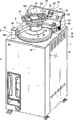
Fig. 1 is the overall perspective view under the lid sealing hold mode of steam autoclave involved in the present invention.
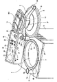
Fig. 2 opens the lid of steam autoclave involved in the present invention for expression and makes the axonometric chart of its state that rotates in the horizontal.
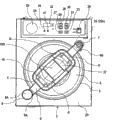
Fig. 3 is the vertical view under the lid sealing hold mode of steam autoclave involved in the present invention.
Fig. 4 for expression from the state of the lid of closing steam autoclave involved in the present invention vertical view with its state that has rotated in the horizontal.
Fig. 5 is the exploded perspective view of the relation of lid, rocking arm and the handle of expression steam autoclave involved in the present invention.
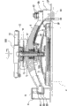
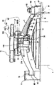
Fig. 6 be the handle of steam autoclave involved in the present invention is rotated and the state of closing cap under the longitudinal sectional view of Handle axis central part.
Fig. 7 is the following direction axonometric chart of the structure of support one side of first sense switch part of expression steam autoclave involved in the present invention and rocking arm.
Fig. 8 is the axonometric chart that is illustrated in the state when the lock-up solenoid valve device stops handle to rotate under the state of the lid of closing steam autoclave involved in the present invention.
Fig. 9 is the lock-up solenoid valve device of steam autoclave involved in the present invention and to the longitudinal sectional view of the power supply section of its power supply.
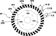
Figure 10 is the figure that is illustrated in the depth figure that is formed by the lower surface of locking component involved in the present invention.
Figure 11 is when the handle of forward rotation steam autoclave involved in the present invention, by the detected output waveform figure of rotation angle detecting device.
Figure 12 is when the handle of backward rotation steam autoclave involved in the present invention, by the detected output waveform figure of rotation angle detecting device.
Figure 13 is the structure chart of the control part of steam autoclave involved in the present invention.
Figure 14 is the graph of a relation with respect to the optical sensor of depth figure involved in the present invention.
Figure 15 is made as the key diagram of the state when closing (OFF) for expression the 3rd sense switch involved in the present invention.
The key diagram of the state when Figure 16 is made as unlatching (ON) for expression the 3rd sense switch involved in the present invention.
Symbol description:
1 ... steam autoclave
2 ... main part
2A ... control chamber
3 ... upper surface open
4 ... vertical inner chamber
5 ... lid
6 ... annular seal ring
7 ... support
8 ... fixed part
9 ... rocking arm
10 ... handle
11 ... pin thread
12 ... female thread
13 ... Handle axis
15 ... second sense switch
16 ... by locking component
19 ... first sense switch
20 ... the lock-up solenoid valve device
21 ... lock pin
21A ... startup portion
21A1 ... start the major diameter rake of subordinate portion
21A2 ... the minor diameter rake on startup portion top
22 ... pressure detecting portion
23 ... start button
24 ... the 3rd sense switch
24A ... the startup portion of the 3rd sense switch
25 ... helical spring
26 ... power switch button
27 ... the reset switch button
28 ... the temperature setting switch button
29 ... the time setting switch button
30 ... shift knob makes progress
31 ... downward shift knob
32 ... display part
33 ... piezometer
35 ... switch activated rod
36 ... helical spring
37 ... decorative shell
38 ... lead-in wire
40 ... groove
41 ... cover plate
45 ... control part
KK ... rotation angle detecting device
NP ... depth figure
NP1 ... outside depth figure
NP2 ... inboard depth figure
SS ... optical sensor
SS1 ... outside optical sensor
SS2 ... inboard optical sensor
The specific embodiment
[embodiment 1]
Below, with reference to the accompanying drawings embodiments of the invention are described.Steam autoclave 1 of the present invention has: vertical inner chamber 4, and it forms opening 3 on the upper surface of main part 2, and is cylindric; Lid 5, the annular seal ring 6 that it has the surrounding edge that is adjacent to opening 3 is used to open or close opening 3; And, steam autoclave 1 also has: rocking arm 9, it disposes support 7 and fixed part 8 the upper surface of main part on the position of opening, the other end 9B as supported end is supported portion's 7 supportings in the mode that can rotate in the horizontal, so that can move up and down with respect to fixed part 8 as a free-ended end 9A; Handle axis 13, its upper end has handle 10, and the bottom is supported in rotating mode and is covered 5, and pars intermedia forms the threaded portion 11 as pin thread, and is screwed in the threaded portion 12 as female thread that forms in the mode that connects rocking arm 9 up and down.Support 7 is fixed on the top panel 2P by bolt 44 from the downside of the top panel 2P of formation main part 2 upper surfaces.Fixed part 8 also is same mounting structure.
The structure of handle 10 is, for the cyclic operating portion of rectangle that will be made of four limits of A, B, C, D and the central part of handle 10 are installed on the Handle axis 13, on handle 10, be provided with installation portion 10S integratedly, this installation portion 10S is to form decorative panel across the mode of opposed two limit A, B in the operating portion, the center bottom 10S1 of installation portion 10S is installed on the Handle axis 13 by bolt etc., and handle 10 and Handle axis 13 are by integrated formation.
In rocking arm 9, its supported end 9B is installed on the support 7 by nut 43, with can rotate in the horizontal and the free end 9A of rocking arm 9 can on move (moving) towards the top mode be supported, be axle with support 7, can make the transversely rotation of rocking arm 9 in regulation.Therefore, under the state that has risen on the position above lid 5 the upper surface open 3 in leaving inner chamber 4, by making the lateral rotation of rocking arm 9 to regulation, lid 5 is thereupon also to the lateral rotation of stipulating, thereby as Fig. 2 and shown in Figure 4, can be on the upper surface open 3 in inner chamber 4 isolating position removable cover 5, thereby can be accommodated in the inner chamber 4 by the sterilization thing, and in inner chamber 4, take out by the sterilization things.
In inner chamber 4, take in by the sterilization thing, and rotate rocking arm 9, simultaneously with the free end 9A embedding fixed part 8 of rocking arm 9 so that cover 5 top positions that are positioned at the upper surface open 3 of inner chamber 4.Fixed part 8 is accommodated mouthful 8B towards the structure of folk prescription to opening for making, and by the rotation of rocking arm 9, the free end 9A of rocking arm 9 accommodates mouthful 8B from this and inserts, and is maintained at and is arranged on the position of this 8C of the portion that stops that accommodating mouthful 8B inboard collision.Under this state, the lid 5 be positioned at inner chamber 4 upper surface open 3 directly over the position.
And, rotate by a direction of rotating the Handle axis 13 of (being called forward rotation again) rotation with a direction of handle 10, move (moving) on the free end 9A with respect to the rocking arm 9 of fixed part 8 towards the top, this mobile (towards the moving of top) that makes progress is subjected to the restriction of the top 8A of fixed part 8, under this state that is restricted, further rotation along with handle 10, lid 5 will move down, thereby annular seal ring 6 will be connected on the upper surface open 3 of inner chamber 4, and be compressed, make upper surface open 3 tegmentums 5 sealings of inner chamber 4.Under the sealing state, carry out desired sterilization action.And,, can open and cover 5 by the backward rotation of the Handle axis 13 of carrying out along with the backward rotation of handle 10.
In this steam autoclave 1, under the state that the pressure in inner chamber 4 has raise, cover 5 if open by operating grip 10, steam will flow out, danger close.The present invention provides a kind of sealing holding device (interlock) of lid 5 in order to avoid this danger.At first, its basic structure is described.
The basic structure of the sealing holding device (interlock) of the lid 5 of steam autoclave 1 of the present invention is, has lock-up solenoid valve device 20, it is used for by no power or energising, thereby make lock pin 21 give prominence to or return action, cover 5 in order to open by operating grip 10 under the state that is implemented in the upper surface open 3 of covering 5 closed cavities 4, and sealed at lid 5 under the state of upper surface open 3 of inner chamber 4, by making lock pin 21 outstanding by lock-up solenoid valve device 20 no powers, thereby stoped handle 10 to opening the rotation of covering 5 direction.
Below the specific embodiment that has adopted this basic structure is described.
At first, the embodiment to the steam autoclave 1 that adopted this basic structure describes.Steam autoclave 1 has: first sense switch 19, and it is used for by being rocking arm 9 rotation in the horizontal at center with support 7, and detects 5 situations that are positioned at the top position of opening 3 of covering; Second sense switch 15, it is set in the fixed part 8, is used to detect the position of moving on the free end 9A of rocking arm 9; Lock-up solenoid valve device 20, it is used to make lock pin 21 to start.Lock-up solenoid valve device 20 makes lock pin 21 give prominence to action, make lock pin 21 return action by energising by no power.Thus, as described later, realized by making lock pin 21 outstanding, thereby kept covering the structure of the state of 5 sealed opens 3.In addition, steam autoclave 1 has also adopted following structure: under the state that makes lock-up solenoid valve device 20 energising, first sense switch 19 detects 5 situations about having moved to the top position of opening 3 from position that opening 3 leaves of covering; Detected at second sense switch 15 under the state of the position of moving on the free end 9A of rocking arm 9,, made the rotation of handle 10 be prevented from, thereby kept covering the state of 5 sealed opens 3 because of the outstanding of lock pin 21 by making lock-up solenoid valve device 20 no powers.
The present invention has considered multiple structure, in order to realizing by making lock-up solenoid valve device 20 no powers, and makes that lock pin 21 is outstanding, thereby stops handle 10 to rotate.Below, with reference to the accompanying drawings wherein a kind of structure is described.In the accompanying drawings, in order to form one, be the center with Handle axis 13 with handle 10, circular by locking component 16 be wholely set with the center bottom 10S1 of the installation portion 10S of handle 10 one on.Though should be by locking component 16 be the center with Handle axis 13, an independent plectane has been installed on center bottom 10S1 with bolt, it also can be by forming discoideus member with center bottom 10S1 is integrally formed.In this structure, close under the state of opening 3 at lid 5, by making lock-up solenoid valve device 20 no powers make lock pin 21 outstanding, outstanding lock pin 21 is inserted into by among the stop hole 16A that forms in the locking component 16, thereby the opening action of the lid 5 that is undertaken by turning handle 10 is prevented from.Rotated with handle 10 by locking component 16, thereby, being inserted into easily among the stop hole 16A in order to make lock pin 21 on the position that stops operating at handle 10, stop hole 16A forms circular-arc slotted hole.
First sense switch 19 is, covers 5 switches that are positioned at the situation of opening 3 top positions in order to detect, and by being rocking arm 9 rotation in the horizontal at center with support 7, and carries out the action of Open-closure (ON-OFF).Specifically as shown in Figure 7, first sense switch 19 is installed in the side of the support plate 17 on the lower position of support 7, and this support plate 17 is installed in the downside of the top panel 2P of the upper surface that forms main part 2.Above the drive division 19A of first sense switch 19, by helical spring 36 application of force switch activated excellent 35 upward, with the mode that can move up and down in vertical direction by from support plate 17 to guided plate 17A, the 17B of the above and below that horizontal direction is extended supporting.By helical spring 36 upward switch activated excellent 35 structure of the application of force be, it connects the top panel 2P of main part 2 and the bottom of support 7, its top 35A is in the position that becomes on the lateral rotation track of rocking arm 9, from the upper surface of support 7 bottoms with to a certain degree outstanding (be to give prominence to 2.5mm in an embodiment), by rocking arm 9 to make cover 5 be positioned at opening 3 directly over the rotation carried out of position, make switch activated excellent 35 to be pushed, thereby make first sense switch 19 start (being unlatching (ON) among the embodiment) towards the below.And, because switch activated excellent 35 run through the bottom of support 7, thereby can prevent the generation of following situation, promptly, owing to be subjected to from operator's hands or by the active force (being called external force) of sterilization thing etc., switch activated excellent 35 distortion, thus the normal startup of first sense switch 19 is hindered.
Below, the concrete structure of the work of first sense switch 19 is described.As Fig. 2 and shown in Figure 4, moved under 5 the state of covering in the position of leaving to the upper surface open 3 in inner chamber 4, switch activated excellent 35 by helical spring 36 application of force and be positioned at outstanding upper limit position upward, under this state, by covering 5 positions that are positioned at directly over the opening 3 and rotate rocking arm 9 to making, make switch activated excellent 35 rounded top 35A, be connected on the rounded cross part 9C of the lower surface of supported end 9B of rocking arm 9 and side surface, and lead by this cross part 9C, in compression helical spring 36, switch activated excellent 35 are pushed downwards, collide at the free end 9A of rocking arm 9 on the position of the 8C of the portion that stops that being arranged on the inboard of accommodating mouthful 8B, switch activated excellent 35 top 35A is positioned at the position of the lower surface that enters rocking arm 9.By switch activated excellent 35 these a series of actions of being pushed downwards, switch activated excellent 35 push the drive division 19A of first sense switch 19, make first sense switch 19 start (being unlatching (ON) among the embodiment).
Below, the concrete structure of the work of second sense switch 15 is described.Shown in Fig. 6 waits, this structure is, the top 8A of fixed part 8 is provided with second sense switch 15; move (moving towards the top) on the free end 9A of rocking arm 9; behind the 8A of the top of butt fixed part 8; move on this and be restricted, and goes out this state (being switch open (ON) in an embodiment) by second sense switch, 15 operation detection.
As mentioned above, be embedded in the fixed part 8 and collision stops under the state of the 8C of portion at the free end 9A of rocking arm 9, lid 5 be positioned at inner chamber 4 upper surface open 3 directly over the position.Like this, be positioned at lid 5 inner chamber 4 upper surface open 3 directly under the state of position, make Handle axis 13 forward rotation by making handle 10 forward rotation, thereby make Handle axis 13 move down (moving) that covering 5 will move down towards the below with respect to rocking arm 9.Annular seal ring 6 is because of covering 5 move down on the upper surface open 3 that is connected to inner chamber 4, by from the further forward rotation handle 10 of this state, reason owing to the female thread 12 that screws togather with pin thread 11; the free end 9A of rocking arm 9 will on move (moving) towards the top, move the restriction that (moving towards the top) is subjected to the top 8A of fixed part 8 on this.On the top 8A of fixed part 8, be provided with second sense switch 15, therefore when moving (moving towards the top) on the free end 9A of rocking arm 9 and being connected to the top 8A of fixed part 8, second sense switch 15 starts (being switch open (ON) in an embodiment).
At this moment, in normal running, because in the way that makes handle 10 forward rotation, second sense switch 15 starts (being switch open (ON) in an embodiment), therefore start the moment of (being switch open (ON) in an embodiment) since second sense switch 15, handle 10 is by further forward rotation, thereby annular seal ring 6 further is compressed, and the degree that makes annular seal ring 6 be close to the upper surface open 3 in the inner chamber 4 strengthens.Therefore, the present invention has considered following situation, promptly, startup (being switch open (ON) in an embodiment) by second sense switch 15, light the display lamp that the control chamber 2A of the upper surface that is arranged on main part 2 is had, thereby will cover 5 and seal the advisory end user of the upper surface open 3 of inner chamber 4, and notify it can begin the situation of sterilizing and moving by starting switch.
Yet, when after second sense switch 15 starts (being switch open (ON) in an embodiment), further make handle 10 forward rotation under annular seal ring 6 becomes by the situation of compressed sufficiently state, because lid 5 is in the state of the upper surface open 3 that has sealed inner chamber 4, thereby it is no problem, but, when just having started (being switch open (ON) in an embodiment) as second sense switch 15, cause under the inadequate situation of sealing of upper surface open 3 of inner chamber 4 because the forward rotation of handle 10 is insufficient, perhaps annular seal ring 6 has been formed by compressed sufficiently state from forward rotation handle 10, in that not starting in the scope of (cutting out (OFF) in an embodiment for switch), second sense switch 15 make handle 10 be reversed rotation, cause under the inadequate situation of sealing of upper surface open 3 of inner chamber 4, from guaranteeing the sealing this point of inner chamber 4, can not assert that it is in perfect state.
In view of this point, the invention provides a kind of technology, promptly, when detecting: be restricted and second sense switch 15 has started the state of (being switch open (ON) in an embodiment) from the moving of the free end 9A of rocking arm 9 (moving) towards the top, further make handle 10 forward rotation when making annular seal ring 6 become by the situation till the compressed sufficiently state, by sterilization action beginning switch (being equivalent to hereinafter described start button 23), can begin the sterilization action.This technology is described in more detail below.
In the present invention, make handle 10 forward rotation arrive annular seal ring 6 to become, have the rotation angle detecting device KK of the rotational angle that is used to detect handle 10 by the abundant situation of compressive state in order to detect current being in.This rotation angle detecting device KK is, be used to detect from second sense switch, 15 detected states handle 10 towards making annular seal ring 6 compressed directions further rotate the device of the situation of predetermined angular, when this rotation angle detecting device KK detects handle 10 when having rotated the situation of predetermined angular, the opening 3 of inner chamber 4 is in tegmentum 5 hermetically sealed states.Detecting under the state of this situation, startup by sterilization action beginning switch (being equivalent to hereinafter described start button 23), make lock-up solenoid valve device 20 no powers, thereby utilize the outstanding of lock pin 21 and stoped the backward rotation of handle 10, make 5 states that are maintained at the upper surface open 3 of closed cavity 4 that cover.
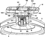
The structure of this rotation angle detecting device KK has shown in Fig. 9, Figure 10 etc.: depth figure NP, its be arranged in coaxial with handle and the circumference that together rotates on; Optical sensor SS, it has light-sensitive device JS, and this light-sensitive device receives from what luminescent device HS sent and is radiated on the depth figure NP and the light that is reflected; By the output (being mainly current value) of light-sensitive device JS corresponding with rotational angle and that change according to depth figure NP, detect the rotational angle of handle 10.Therefore, depth figure NP is formed on, be installed on and co-rotational mode coaxial on the surface of rotor plate KB on handle 10 or the Handle axis 13 with the rotation of handle 10, optical sensor SS with the opposed position of depth figure NP on be installed in rocking arm 9 one sides.In an embodiment, rotor plate KB is by being constituted by locking component 16, by the lower surface of locking component 16, be formed with and locate the depth figure NP that is arranged on the circumference, on the support plate 18 that is installed on the rocking arm 9, optical sensor SS so that luminescent device HS and light-sensitive device JS mode up be mounted thereon.
In the present invention, for the backward rotation of the forward rotation that detects handle 10 (towards the rotation of the direction of closing cap 5) and handle 10 (towards opening the rotation of covering 5 direction), depth figure NP is constituted by being formed on concentric circles by outside depth figure NP1 on the lower surface of locking component 16 and inboard depth figure NP2, and outside depth figure NP1 and inboard depth figure NP2 are configured with 1/4th phase contrast (being 2.5 degree phase contrasts among the embodiment) of the unit angle (among the embodiment be 10 degree) of regulation.And, with respectively with outside depth figure NP1 and the corresponding mode of inboard depth figure NP2, be configured in up on the support plate 18 that is installed on rocking arm 9 as outside optical sensor SS1 and the inboard optical sensor SS2 of optical sensor SS.The outside optical sensor SS1 and inboard optical sensor SS2 are the reflection type optical pick off of the transmitting-receiving light one that luminescent device HS and light-sensitive device JS assembled by one, its structure is, the luminescent device HS of outside optical sensor SS1 and the optical axis of light-sensitive device JS are, with respect to outside depth figure NP1 approximate vertical, the luminescent device HS of inboard optical sensor SS2 and the optical axis of light-sensitive device JS are, with respect to inboard depth figure NP2 approximate vertical.And outside optical sensor SS1 is configured on the identical radius with inboard optical sensor SS2.
The outside depth figure NP1 and inboard depth figure NP2 also can be, the form of printing black-and-white two color figure on by the lower surface of locking component 16.But, in an embodiment,, be to handle forming glassy surface by electroless plating nickel, and on this face, apply the printing of single black by the structure of the lower surface of locking component 16 for raising is equivalent to the reflectance of light-colored part of white.As shown in the Examples, by will be, thereby compare, reduced cost with the situation of establishing independent rotor plate KB outside by locking component 16 in addition by locking component 16 double as rotor plate KB.In addition, because rotor plate KB is by being constituted by locking component 16, thereby the lock pin 21 of rotational angle when being easy to stipulate to make handle 10 to turn to normal sealing state and lock-up solenoid valve device 20 is outstanding and card ends position in stop hole 16A.
Rotation along with handle 10, the rectangular pulse that sends from luminescent device HS as light and occurred by the output (being mainly current value) of the light-sensitive device JS of depth figure NP reflex time, as Figure 11 and shown in Figure 12, with the output (being mainly current value) that forms the corresponding luminescent device JS of white portion of light-colored part among the depth figure NP be H level (high level), with form depth figure NP in the black part of dark part to divide the output (being mainly current value) of corresponding light-sensitive device JS be L level (low level).And the white portion NPW on the same circumference is identical with black part NPB width, will be formed the unit angle (being 10 degree among the embodiment) of regulation by the pitch PT that a white portion NPW and black part NPB constitute.Therefore, the width of the width of a white portion NPW and a black part NPB is respectively the unit angle (among the embodiment be 10 degree) of regulation half (being 5 degree among the embodiment).Thus, in an embodiment, moving 10 degree of handle 10 revolutions just produce a pulse (paired pulses that is made of H level and L level), and the rotations by 90 degree will produce 9 pulses.
Outside depth figure NP1 and inboard depth figure NP2 are constituted as, a phase contrast (being the phase contrasts of 2.5 degree among the embodiment) of/4th with the unit angle (among the embodiment be 10 degree) of regulation is configured, and the judgement of the rotation direction of handle 10 is to be that standard is judged with outside depth figure NP1.Promptly, when never reflecting (the dark part of corresponding outside depth figure NP1) by the outside detected result of optical sensor SS1 when being transformed into reflection (light-colored part of depth figure NP1 outside corresponding), whether detected the rotation direction that handle 10 is judged in reflection (being light-colored part or the corresponding dark part corresponding to inboard depth figure NP2) according to inboard optical sensor SS2.Like this, be transformed into reflex time when never reflecting by the outside detected result of optical sensor SS1, internally whether sidelight pick off SS2 has detected to reflect and has detected, but, such detection is at short time (μ sec: be to be the short time of unit with the microsecond, be set at the time of comparing enough weak points with the velocity of rotation of handle) in accordance with regulations number of times (for example 2~3 times) detect the output of outside optical sensor SS1 and the output of inboard optical sensor SS2, if this testing result is identical, then this result is adopted as normal detection data, survey thereby can tackle the flase drop that causes because of noise etc.
Below, specifically tell about the judgement of the rotation direction of adversary's handle 10.That is, as shown in figure 11, corresponding outside depth figure NP1 and the output pulse that produces and corresponding inboard depth figure NP2 and the output pulse that produces generates with the phase contrasts of 2.5 degree.In Figure 11, output state when illustrating handle 10 forward rotation (rotation on the direction of closing cap 5), when when the t1 that is detected by outside optical sensor SS1 observes constantly, never reflect (the dark part of corresponding outside depth figure NP1) by the outside detected result of optical sensor SS1 and be transformed into reflection (light-colored part of corresponding outside depth figure NP1), the output (being mainly current value) of the light-sensitive device JS of outside optical sensor SS1 becomes H level (high level).The output (being mainly current value) of the light-sensitive device JS of inboard optical sensor SS2 is L level (low level) at this moment, and thus, control part 45 is judged as handle 10 and carries out forward rotation (rotations on closing cap 5 directions), and instrumentation rotational angle at this moment.
On the other hand, in Figure 12, output state when illustrating handle 10 backward rotation (opening the rotation of covering on 5 directions), when when the t1 that is detected by outside optical sensor SS1 observes constantly, never reflect (the dark part of corresponding outside depth figure NP1) by the outside detected result of optical sensor SS1 and be transformed into reflection (light-colored part of corresponding outside depth figure NP1), the output (being mainly current value) of the light-sensitive device JS of outside optical sensor SS1 is H level (high level).The output (being mainly current value) of light-sensitive device JS according to the inboard optical sensor SS2 of this moment is H level (high level), and the action by control part 45, carry out backward rotation (opening the rotation of covering on 5 directions) thereby be judged as handle 10, and instrumentation rotational angle at this moment.
In this way, because according to the output of outside optical sensor SS1 and the output of inboard optical sensor SS2, having judged handle 10 is to carry out forward rotation (rotations on closing cap 5 directions), still carrying out backward rotation (opening the rotation of covering on 5 directions), thereby, for example, from the 2nd sense switch 15 detected states, make handle 10 after the direction of compression annular seal ring 6 is further rotated 90 degree, if being reversed again, handle 10 rotated 20 degree, then 90 degree-20 degree=70 degree are judged as handle 10 by control part 45 and are in the state that has been rotated 70 degree from the 2nd sense switch 15 detected states.
In the steam autoclave 1 of embodiment, when further handle 10 being rotated 90 when spending to the direction of compression annular seal ring 6 from the 2nd sense switch 15 detected states, be judged as annular seal ring 6 and fully compressed, and make the opening 3 of inner chamber 4 be in normal sealing state by covering 5.And, if be reversed again more than rotation 20 degree from this state handle 10, then by control part 45 by for example lighting emergency warning lamp or making the mode of buzzer startup etc. make alarm device 34 work, warn error situation, and the situation of the sealing state outofkilter of the opening 3 of notice inner chamber 4.If just finish under the state of less than 70 degree from the angle of the further turning handle 10 of the 2nd sense switch 15 detected states lever operated, then by alarm device 34, the situation of the sealing state outofkilter of the opening 3 of notice inner chamber 4.
Like this, if from the 2nd sense switch 15 detected states, with handle 10 further to angle that the direction of compression annular seal ring 6 is rotated more than predetermined angular (being 70 degree among the embodiment), then be in the state of tegmentum 5 sealings at the opening 3 that is judged as inner chamber 4 by control part 45, and light the display lamp 47 that is arranged on the control chamber 2A showing this kind situation, can begin the state of sterilizing and moving by the startup of sterilization action beginning switch (being equivalent to hereinafter described start button 23) thereby form.And, if the rotational angle of handle 10 is less than predetermined angular (among the embodiment be 70 degree), the situation of the sealing state outofkilter of the opening 3 by alarm device 34 notice inner chambers 4 then.
The upper surface of main part 2 is provided with control chamber 2A.By to being arranged on unlatching (ON) operation of the start button 23 on the control chamber 2A, make the starting switch in the control chamber 2A corresponding start (being switch open (ON) this moment), thereby sterilization action sign on is issued with it.In addition, among the described control chamber 2A, dispose that the action pattern that is used for steam autoclave 1 is selected and the switching manipulation portion of operation condition setting etc., and take in the control part 45 that comprises relevant control circuit etc.
In figure such as Fig. 3, illustrate a kind of in the configuration structure of switching manipulation portion of being configured on the control chamber 2A upper surface etc.In the drawings, 23 is start button, 26 is power switch button, 27 is the reset switch button, 28 is the temperature setting switch button, 29 is the time setting switch button, and 30 are each downward shift knob that makes temperature or time decline (minimizing) when opening (pushing) for each rise upwards shift knob, 31 of (increases) of temperature or time that makes when opening (pushing).32 for to by temperature setting switch button 28, time setting switch button 29, upwards shift knob 30 and the display part that shows of the temperature and time that sets of shift knob 31 downwards.33 are the piezometer to being shown by the pressure in pressure detecting portion (being also referred to as pressure transducer) the 22 detected inner chambers 4.Alarm device 34 and display lamp 47 also are configured on the upper surface of control chamber 2A.
When setting as the temperature of steam autoclave 1 sterilising conditions, open temperature setting switch button 28, by shift knob 30 upwards and downwards shift knob 31 set sterilising temps.In addition, when setting as the time of sterilising conditions, opening time configuration switch button 29, and by shift knob 30 upwards and downwards shift knob 31 set sterilization time.When resetting, after opening reset switch button 27, by aforesaid operations, set sterilising temp and/or sterilization time once more.
Next, the control action to steam autoclave 1 is described as follows.Make on and off switch unlatching etc. by operation, the state (power connection state) that steam autoclave 1 is in added power supply by the power switch button 26 of steam autoclave 1.By this additional power source, the coil 20A of lock-up solenoid valve device 20 is energized, thereby makes lock pin 21 opposing helical springs 25 (compression helical spring 25) and be pulled into and attract position (in the drawings, becoming the state of returning that has moved downwards).Therefore, the state that lock pin 21 is in compression helical spring 25 and is attracted downwards, the top of lock pin 21 is positioned at than the position of more being leaned on the below by locking component 16.
Under this state, as Fig. 2 and shown in Figure 4, be axle with support 7, the position removable cover 5 that staggers to upper surface open 3 from inner chamber 4, and will be accommodated in the inner chamber 4 by the sterilization thing.After having taken in, as mentioned above,, set sterilising temp and sterilization time as steam autoclave 1 working condition by to being configured in the operation of the switching manipulation portion on the control chamber 2A upper surface by the sterilization thing.The setting of this sterilization operation condition also can be carried out before taking in by the sterilization thing.And, be in the top position of the upper surface open 3 in the inner chamber 4 by rotating rocking arm 9 so that cover 5, thereby make first sense switch 19 start (this moment, switch was for opening (ON)).Meanwhile the free end with rocking arm 9 is embedded in the fixed part 8.Thereby fixed part 8 is for forming the structure of accommodating mouthful 8B in unidirectional upper shed, and by the rotation of rocking arm 9, the free end of rocking arm 9 is accommodated mouthful 8B from this and inserted, and is maintained at and is arranged on the position of this 8C of the portion that stops that accommodating mouthful 8B inboard collision.Under this state, the lid 5 be positioned at inner chamber 4 upper surface open 3 directly over the position.
Under this state, make Handle axis 13 forward rotation by making handle 10 forward rotation, make Handle axis 13 move down (moving) towards the below with respect to rocking arm 9, move down thereby cover 5.By covering 5 move down, annular seal ring 6 is compressed in the upper surface open 3 that is connected to inner chamber 4, thereby upper surface open 3 is closed.By further make handle 10 forward rotation from this state, thereby reason owing to the female thread 12 that screws togather with pin thread 11; free end of rocking arm 9 will on move (moving) towards the top, and should on move the restriction that (moving towards the top) is subjected to the top 8A of fixed part 8.By further make handle 10 forward rotation from this state, thereby be under the bearing state of benchmark with rocking arm 9, further compress annular seal ring 6, and make and cover 5 and move down (moving) towards the below with Handle axis 13, forming the state of further compression annular seal ring 6, and form air-tight states in the inner chamber 4.When moving (moving towards the top) on the free end of rocking arm 9 and be connected to the top 8A of fixed part 8, second sense switch 15 starts (be switch open (ON) this moment).
As mentioned above, detect by first sense switch 19 cover 5 be in inner chamber 4 upper surface open 3 directly over position and detect by second sense switch 15 cover 5 and close under the state of upper surface open 3 of inner chamber 4, further rotation by handle 10, make and cover 5 and move down in the above described manner, thereby realize the sealing of opening 3.And, detection according to rotation angle detecting device KK, sealed under the state of opening 3 at lid 5, by the unlatching (ON) that is arranged on the start button 23 on the control chamber 2A is operated, make the starting switch in the control chamber 2A corresponding start (switch open (ON) this moment), thereby sterilization action sign on is issued with it.After receiving this sterilization action sign on, make lock-up solenoid valve device 20 no powers by control part 45, lock pin 21 is given prominence to upward by helical spring 25, outstanding lock pin 21 is inserted into and is formed on by among the stop hole 16A on the locking component 16, thereby has stoped the opening action of the lid 5 that is undertaken by the rotation of handle 10.
The pass of lock-up solenoid valve device 20 and the 3rd sense switch 24 is, as shown in Figure 8, the a pair of support plate 18 in front and back that is installed in mode with bolt on the rocking arm 9 from front and back clamping rocking arm 9, therein on the installation portion 18A of a support plate 18, so that lock pin 21 is equipped with lock-up solenoid valve device 20 towards the mode of approximate vertical.And the 3rd sense switch 24 is installed on the installation portion 18A of support plate 18, so that the top ends A1 of the 24A of startup portion of the 3rd sense switch 24 is corresponding in the mode that moves up and down with lock pin 21 one and the cyclic drive division 21A that is provided with.
When being implemented in lock-up solenoid valve device 20 no powers, make on the lock pin 21 by helical spring 25 and to move, promptly outstanding upward, and make drive division 21A drive the 3rd sense switch 24 operate as normal thus, thereby adopt following structure as the structure of moving distance (distance that moves towards the top) on the restriction lock pin 21, promptly, the upper end of a crooked described support plate 18, thereby form the retainer 18B of approximate horizontal, retainer 18B is positioned at by the downside of locking component 16, and this retainer 18B is run through on the top of lock pin 21.Thus, when lock-up solenoid valve device 20 no powers, move (moving) on the lock pin 21 towards the top, the lower surface of the upper end of drive division 21A collision retainer 18B, make lock pin 21 greatly on move (towards moving of top) and be restricted.Under this state, become the state that inserts stop hole 16A by the top of locking component 16, drive division 21A is in the state that makes the 3rd sense switch 24 operate as normal.
As Figure 15 and shown in Figure 16, lock pin 21 be provided with cyclic support 21T midway, cyclic drive division 21A is made by synthetic resin, forms the bowl-shape of diapire back-off up, and is retained as diapire on it is placed on state on the support 21T in the mode that is run through by lock pin 21.And support 21T has the effect of the support of the upper end that is used to support helical spring 25 concurrently.In order to make the 3rd sense switch 24 carry out work, be that top and pars intermedia diameter are little, the shape that lower diameter is big with the shape set of the 21A of startup portion in the bottom of cyclic drive division 21A.As its concrete shape, in the outer surface of drive division 21A, cyclic major diameter rake 21A1 is formed at the bottom, in the upper section of major diameter rake 21A1, formed pars intermedia 21A3 and diameter than the pars intermedia 21A3 littler minor diameter rake 21A2 of diameter on top less than the tubular of major diameter rake 21A1.
According to this structure, when 20 energisings of lock-up solenoid valve device, as shown in figure 15, the 21A of startup portion descends with lock pin 21, make the top of the 24A of startup portion of the 3rd sense switch 24 be in the corresponding state of minor diameter rake 21A2 (in an embodiment for contacting minor diameter rake 21A2) with the 21A of startup portion, thereby make the 3rd sense switch 24 be in idle state (in an embodiment for closing (OFF)).Therefore, the sterilization action by control part 45 controls is in the state that does not start (beginning).
And, when lock-up solenoid valve device 20 no powers, as shown in figure 16, the 21A of startup portion raises with lock pin 21, make the lower surface of the top collision retainer 18B of the 21A of startup portion, and Tu Chu lock pin 21 is inserted into and is formed on by in the stop hole 16A on the locking component 16 upward.Under this state, the major diameter rake 21A1 that the top of the 24A of startup portion of the 3rd sense switch 24 is activated portion 21A bottom pushes, thereby makes the 3rd sense switch 24 start (being unlatching (ON) among the embodiment).Owing to make starting switch start (this moment, switch was for opening (ON)) by the way, therefore pass through the startup (this moment, switch was for opening (ON)) of the 3rd sense switch 24, move thereby start (beginning) sterilization according to the sterilising conditions that configures by control part 45.
In addition, become no power when lock-up solenoid valve device 20 and make when moving on the lock pin 21, between the adjacent stop hole 16A of the upper end of lock pin 21 collision by the lower surface of the part of locking component 16 (16T part as shown in Figure 8), thereby become the state that rises and stoped, under this state (this state is the counter-rotational state that lock pin 21 does not suppress handle 10), shown in the chain-dotted line among Figure 16, the top of the 24A of startup portion of the 3rd sense switch 24 is corresponding with pars intermedia 21A3, because the 3rd sense switch 24 is not in the state that starts (being unlatching (ON) among the embodiment) under this state, thereby the sterilization action starts (beginning).Therefore, do not suppress at this lock pin 21 under the counter-rotational state of handle 10,, thereby can guarantee safety because the sterilization action does not start (beginning).
And, adopting the startup 21A of portion to be fixed under the situation of the structure on the lock pin 21, because the assembly error of each parts, might produce the major diameter rake 21A1 situation of the powerful ground started by press 24A of portion too that makes startup portion 21A bottom because of moving on the lock pin 21.Yet, if the structure of the 21A of startup portion is set at, diapire is placed on the support 21T in the mode that is run through by lock pin 21 and keeps this state in mode to a certain degree free to rotate on it, when then on because of lock pin 21, moving the major diameter rake 21A1 that makes the 21A of startup portion and pushing the 24A of startup portion of the 3rd sense switch 24 too powerfully, the action of giving that the 21A of startup portion to a certain degree makes a concession, thus the damage of the 3rd sense switch 24 that causes by too pushing of the 24A of startup portion can be prevented.
In this way, between the adjacent stop hole 16A of the upper end of lock pin 21 collision by the lower surface of the part of locking component 16 (16T part as shown in Figure 8), make under the state that its rising stoped, the sterilization action will can not start (beginning).At this moment, by making handle 10 a little to forward or backward rotation, thereby lock pin 21 is broken away from rise the state that is obstructed and rise, and be inserted among the stop hole 16A, and the major diameter rake 21A1 that the 24A of startup portion is activated the 21A of portion pushes, and makes the 3rd sense switch 24 start (this moment, switch was for opening (ON)).At this moment, if it is big that the backward rotation angle of handle 10 becomes, and as mentioned above, until reaching when making the rotational angle that is rotated from second sense switch, 15 detected state handles 10 less than the state of predetermined angular (being 70 degree the embodiment), the sealing state outofkilter of the opening 3 of inner chamber 4, thereby this state is notified by the action of alarm device 34.Therefore, can make user notice this situation, and can be by the mode that described power-off is opened after once again, if perhaps have reset switch then by opening the mode of reset switch, thereby from beginning to operate again at first.
As mentioned above, by starting (beginning) sterilization action, the water of ormal weight is injected in the inner chamber 4 automatically.And, also can adopt in advance water with ormal weight to be stored in structure in the inner chamber 4.In addition, by beginning this sterilization action, heater 46 on the bottom that is arranged in the inner chamber 4 is energized, thereby make the water heating evaporation in the inner chamber 4, and by control part 45 action of sterilizing, after the operation of regulations such as the sterilization process of having carried out regulation, the deairing step in the inner chamber 4, finish the sterilization action.
Because of the sterilization release has been reduced under the state below the setting pressure in the inner chamber 4, the demonstration of notice sterilization release appears on the display part 32.This demonstration literal by for example " sterilization release " etc. is displayed on the display part 32.In addition, this moment, inner chamber 4 interior pressure can carry out safety verification by the demonstration of observing piezometer 33.Because according to this demonstration can confirm the to sterilize end of action, thereby by carrying out the backward rotation operation of handle 10, cover 5 upper surface open 3 that are moved upward and break away from inner chamber 4 thereby make.Under this state, rocking arm 9 is rotated and make and cover 5 and move to the position that the upper surface open 3 from inner chamber 4 staggers, thereby can take out in the inner chamber 4 by the thing of sterilizing.
As indicated above, in an embodiment, after sterilization action beginning, except in the sterilization action, as long as be under the state that pressure in the inner chamber 4 have risen, just can keep and to open the state of lid by the rotation of handle 10, thereby can avoid owing to steam flows out the danger that causes by lock-up solenoid valve device 20.And, if because the pressure in the inner chamber 4 is reduced to setting following (is zero air pressure in an embodiment ... atmospheric pressure), therefore then can open and cover 5, can avoid, because of the pressure inner chamber 4 in covers 5 danger that the steam outflow that takes place caused that are opened when higher by the rotation of handle 10.In addition, for the existing steam autoclave that has been in use, by appending the sealing holding device of lid 5 of the present invention, also can improve the safety of existing steam autoclave at an easy rate, thereby can not replace existing steam autoclave and continue use safely, and can bring into play the effect of reduction of expenditure fully.
In the above-described embodiments, Security Countermeasures owing to have a power failure waiting power supply that causes steam autoclave 1 to be cut off have also been proposed.That is, because in the sterilization of steam autoclave 1 action, the pressure in the inner chamber 4 is higher, thereby when the power supply of steam autoclave 1 under this state is cut off, be opened then as operculum 5 that inner chamber 4 interior steam will spray at that time, very dangerous.Therefore, when the power supply of steam autoclave 1 was cut off, lock-up solenoid valve device 20 is in closed (OFF) (non-energising), so that lock pin 21 is kept the state that is embedded in by among the stop hole 16A of locking component 16, thereby can avoid above-mentioned danger.。
As mentioned above, if at first sense switch 19, second sense switch 15, rotation angle detecting device KK, when the 3rd sense switch 24 starts according to said sequence, control and the action that begins to sterilize by control part 45, and when starting not according to said sequence, control and do not begin sterilization action by control part 45, then constituted the steam autoclave 1 that to realize safe action.In this case, when the sterilization action does not begin, if give a warning by control part 45 control warning devicess 34, for example make warning light light or make buzzer action etc., then user will be noted that this situation, and can by earlier described on and off switch is closed (OFF) open (ON) again or when if reset switch is arranged with its unlatching (ON), thereby operate again from beginning at first.
In addition, lid 5 is connected with Handle axis 13, covers 5 structures of rotating along with the rotation of Handle axis 13 though also can adopt to make, in this case because the friction of annular seal ring 6 and upper surface open 3 can cause annular seal ring 6 damaged easily.In order to address this problem, as shown in Figure 6, make the cyclic joint portion 13A that is formed on Handle axis 13 lower ends be in the sliding state that is embedded among the joint portion 5A that covers 5 central parts, can not rotate, make the structure that can rotate freely that is connected to become of the two thus along with the rotation of Handle axis 13 so that cover 5.Particularly, form by the bolt 5P that is screwed into from the side among the 5A of joint portion, this bolt 5P stretches out to the inside, enters and be incorporated into the joint portion 13A of Handle axis 13 by this bolt 5P, thereby cover 5 and supported by Handle axis 13 to cover 5 states that can not rotate, to make along with the rotation of Handle axis 13.Therefore, though constituted cover 5 can move up at upper and lower along with the rotation of Handle axis 13, the structure that can thereupon rotate not.
In the above description, be to move will covering 5 the positions of upper surface open 3 in the inner chamber 4 that staggers, and in inner chamber 4, taken in by under the state of sterilization thing, by the operation that is arranged on the switching manipulation portion on the control chamber 2A, carry out the selection of action pattern of steam autoclave 1 and the setting of operation condition, set sterilising conditions.In addition, also can be in the following way, that is, wait by the operation of switching manipulation portion and set after the sterilising conditions, will cover 5 the positions of upper surface open 3 in the inner chamber 4 that staggers again and move, and in inner chamber 4, take in by the sterilization thing.
Covered by the decorative shell 37 of front and back respectively from the front and back of rocking arm 9 by locking component 16, support plate 18, lock-up solenoid valve device 20, the 3rd sense switch 24, so that these parts can't see that wherein the decorative shell 37 before and after is by on the support plate 18 before and after being installed in screw from the outside.In addition, to the lead-in wire 38,38 of lock-up solenoid valve device 20 and the 3rd sense switch 24 power supply usefulness by with following state distribution, promptly, from being configured in the substrate of the control part 45 in the control chamber 2A, in main part 2 and run through the top panel 2P of main part 2 and near support 7, pass, and be incorporated in be formed on groove 40 on rocking arm 9 lower surfaces along rocking arm 9 in, and covered by the cover plate 41 that is installed on rocking arm 9 lower surfaces with screw 48.By this structure, though because some situation causes dripping from the top of rocking arm 9 water droplet, also can in this water droplet, protect and firmly go between 38.In addition; lead-in wire runs through the top panel 2P of main part 2 in 38 and arrives the part at groove 40 places of rocking arm 9; covered and protection by flexible shells 39 such as rubber, and its part midway is held ring 42 supportings with mobilizable state, with fully respective rocker arm 9 rotation of direction to the left and right.
Because depth figure of the present invention, so long as coaxial with described handle and carry out that the location structure arranged gets final product on the circumference of identical rotation, thereby can be in the following situation any one, promptly, its can for, the form that forms depth figure on the surface that is installed in the rotor plate on described handle or the described Handle axis and described handle for circular situation under in the form of the lower surface printing depth figure of this handle.Because as a kind of situation wherein, described in an embodiment rotor plate is by being constituted by locking component 16, thereby, not only has the effect that reduces cost, and, can be easy to be determined to the outstanding and card of the lock pin 21 of the rotational angle of the turning handle 10 till the normal sealing state and lock-up solenoid valve device 20 and end position in stop hole 16A.
In addition, for existing steam autoclave in use, by increasing the sealing holding device of lid 5 of the present invention, can be easy to improve the safety of existing steam autoclave, substitute existing steam autoclave and just can continue to use safely thereby need not buy new steam autoclave, given full play to the effect of reduction of expenditure.
Industrial utilizability
The present invention is not limited to the foregoing description, and the steam autoclave that it can also be applicable to the various forms that adopt vertical inner chamber mode in technical scope of the present invention, comprises various forms.
Claims (6)
1. steam autoclave, its structure is, has:
Vertical inner chamber, it is in the upper surface upper shed of main part; Lid is used to open or close described opening, and has the annular seal ring of fitting with the circumference of described opening; Rocking arm, it disposes support and fixed part on the position of described opening in the upper surface of described main part, and the free end of this rocking arm can move up and down with respect to described fixed part, and the other end is supported in mode that can lateral rotation by described support; Handle axis, its upper end has handle, and described lid is supported in the bottom, and the threaded portion that is formed at pars intermedia screws togather with the threaded portion that forms in the mode that runs through described rocking arm up and down; Described steam autoclave rotates by described handle described Handle axis is rotated, and causes described lid to move down, and makes described annular seal ring be connected to described opening, and moves on the free end of described rocking arm, and move by described fixed part on being somebody's turn to do and limit;
Described steam autoclave is characterised in that,
Have: sense switch, it is set on the described fixed part, is used to detect the state that the free end of described rocking arm is limited by described fixed part; The lock-up solenoid valve device, it stops the rotation of described handle by outstanding when the no power and the effect lock pin return when the energising has sealed at described lid under the state of described opening; Rotation angle detecting device, it is used to detect the rotational angle of described handle;
When described rotation angle detecting device detects, to the direction of the described annular seal ring of compression when being rotated predetermined angular, the no power by described lock-up solenoid valve device is maintained under the state of the described opening of sealing described lid from the described handle of the detected state of described sense switch.
2. steam autoclave, it has:
Vertical inner chamber, it is in the upper surface upper shed of main part; Lid is used to open or close described opening, and has the annular seal ring of fitting with the circumference of described opening; Rocking arm, it disposes support and fixed part on the position of described opening in the upper surface of described main part, and its free end can move up and down with respect to described fixed part, but the other end is supported by the mode of described support with lateral rotation; Handle axis, its upper end has handle, and described lid is supported in the bottom, and the threaded portion that is formed at pars intermedia screws togather with the threaded portion that forms in the mode that runs through described rocking arm up and down; Described steam autoclave makes described Handle axis rotation by the rotation of described handle and the described rocking arm that causes moves on free-ended, limited by described fixed part, and by moving down of described lid described opening is closed, thereby intracavity utilize steam to being sterilized by the sterilization thing in described;
Described steam autoclave is characterised in that,
Have: first sense switch by being the lateral rotation of the described rocking arm at center with described support, and detects the top position that described lid is positioned at described opening; Second sense switch is set on the described fixed part, and the free-ended superior displacement that is used to detect described rocking arm is put; The lock-up solenoid valve device, it is by outstanding when the no power and the effect lock pin return when the energising, thereby has sealed at described lid under the state of described opening, stops the rotation of described handle; The 3rd sense switch is used to detect the action of described lock pin; The rotation angle detecting device of described handle, it is used for detecting from the detected state of described second sense switch, and described handle has been rotated the situation of predetermined angular to the direction of the described annular seal ring of compression;
When described first sense switch detects the top position that described lid has moved to described opening, and under the described detected state of described rotation angle detecting device, startup by sterilization action beginning switch makes described lock-up solenoid valve device no power, thereby utilize the outstanding of described lock pin and stop the rotation of described handle, make described lid be maintained at the state of the described opening of sealing;
Outstanding by described lock pin, described the 3rd sense switch starts, thereby begins to sterilize action.
3. steam autoclave as claimed in claim 1 or 2 is characterized in that,
Described rotation angle detecting device has: depth figure, and it is arranged in described handle on the circumference coaxial and that together rotate; Optical sensor, it has light-sensitive device, and this light-sensitive device receives and sends and be radiated on the described depth figure and the light that is reflected from luminescent device;
By output, detect the rotational angle of described handle because of the described light-sensitive device of the corresponding variation of described depth figure with rotational angle.
4. steam autoclave as claimed in claim 3 is characterized in that,
Described depth figure is formed on the side surface of rotor plate, described rotor plate is installed on described handle or the described Handle axis in mode coaxial with the rotation of described handle and that together rotate, described optical sensor be installed in described rocking arm one side with the opposed position of described depth figure on.
5. steam autoclave as claimed in claim 4 is characterized in that,
Described rotor plate is, with described Handle axis be the center be installed on the described handle and be formed be used for the stop hole that ends with outstanding described lock pin card circle by locking component, described depth figure is formed on described by on the lower surface of locking component, and described optical sensor is configured in described rocking arm one side of described depth figure below.
6. as any described steam autoclave in the claim 3 to 5, it is characterized in that:
Described depth figure is made of outside depth figure that is formed on the concentric circles on described rotor plate one side surface and inboard depth figure, described outside depth figure and described inboard depth figure are configured with the phase contrast of regulation, and dispose described optical sensor respectively with the described outside of correspondence depth figure and described inboard depth figure, according to corresponding to the described optical sensor of described outside depth figure with corresponding to the output of the described optical sensor of described inboard depth figure, detect the forward rotation angle and the backward rotation angle of described handle, and poor according to described forward rotation angle and backward rotation angle, the opening that detects described inner chamber is in normal sealing state.
Applications Claiming Priority (4)
| Application Number | Priority Date | Filing Date | Title |
|---|---|---|---|
| JP2009-203367 | 2009-09-03 | ||
| JP2009203367 | 2009-09-03 | ||
| JP2009226469A JP5300678B2 (en) | 2009-09-03 | 2009-09-30 | Steam sterilizer |
| JP2009-226469 | 2009-09-30 |
Publications (2)
| Publication Number | Publication Date |
|---|---|
| CN102000352A true CN102000352A (en) | 2011-04-06 |
| CN102000352B CN102000352B (en) | 2013-11-06 |
Family
ID=43808220
Family Applications (1)
| Application Number | Title | Priority Date | Filing Date |
|---|---|---|---|
| CN 201010110998 Expired - Fee Related CN102000352B (en) | 2009-09-03 | 2010-01-29 | Steam sterilizer |
Country Status (1)
| Country | Link |
|---|---|
| CN (1) | CN102000352B (en) |
Cited By (2)
| Publication number | Priority date | Publication date | Assignee | Title |
|---|---|---|---|---|
| CN114652867A (en) * | 2022-01-14 | 2022-06-24 | 安徽圣泰检测科技有限公司 | Multi-effect sterilization pot |
| CN115282301A (en) * | 2022-08-26 | 2022-11-04 | 青岛澳柯玛生物医疗有限公司 | Sealed self-locking steam sterilizer |
Citations (4)
| Publication number | Priority date | Publication date | Assignee | Title |
|---|---|---|---|---|
| JP2000237287A (en) * | 1999-02-25 | 2000-09-05 | Miura Co Ltd | Sealing method of steam sterilizer |
| CN2905065Y (en) * | 2006-05-26 | 2007-05-30 | 陈俊慧 | A seal structure of horizontal pressurized steam sterilizer |
| JP2008229201A (en) * | 2007-03-23 | 2008-10-02 | Sanyo Electric Co Ltd | Steam sterilizer |
| CN201200628Y (en) * | 2008-05-29 | 2009-03-04 | 山东新华医疗器械股份有限公司 | Quick-opening double-stage sealed steam sterilizer |
-
2010
- 2010-01-29 CN CN 201010110998 patent/CN102000352B/en not_active Expired - Fee Related
Patent Citations (4)
| Publication number | Priority date | Publication date | Assignee | Title |
|---|---|---|---|---|
| JP2000237287A (en) * | 1999-02-25 | 2000-09-05 | Miura Co Ltd | Sealing method of steam sterilizer |
| CN2905065Y (en) * | 2006-05-26 | 2007-05-30 | 陈俊慧 | A seal structure of horizontal pressurized steam sterilizer |
| JP2008229201A (en) * | 2007-03-23 | 2008-10-02 | Sanyo Electric Co Ltd | Steam sterilizer |
| CN201200628Y (en) * | 2008-05-29 | 2009-03-04 | 山东新华医疗器械股份有限公司 | Quick-opening double-stage sealed steam sterilizer |
Cited By (2)
| Publication number | Priority date | Publication date | Assignee | Title |
|---|---|---|---|---|
| CN114652867A (en) * | 2022-01-14 | 2022-06-24 | 安徽圣泰检测科技有限公司 | Multi-effect sterilization pot |
| CN115282301A (en) * | 2022-08-26 | 2022-11-04 | 青岛澳柯玛生物医疗有限公司 | Sealed self-locking steam sterilizer |
Also Published As
| Publication number | Publication date |
|---|---|
| CN102000352B (en) | 2013-11-06 |
Similar Documents
| Publication | Publication Date | Title |
|---|---|---|
| US8071933B2 (en) | Photochromic optically keyed dispenser | |
| KR101472236B1 (en) | Pressure detection system for a pressure cooker | |
| US20070204925A1 (en) | Multifunctional faucet | |
| IT202000013432A1 (en) | WASHING AGENTS DISPENSER FOR DISHWASHERS | |
| JP2009000558A (en) | Medical fluid injector | |
| JP5709916B2 (en) | Steam sterilizer | |
| KR20090075068A (en) | Refrigerator having a dispenser unit and a method of using the same | |
| ES2238567T3 (en) | DEVICE FOR DISPENSING FLUID PRODUCTS, SUCH AS FOOD PRODUCTS, FROM DEFORMABLE CONTAINERS. | |
| US20160046478A1 (en) | Water dispenser | |
| EP3463030B1 (en) | Motor driven in-door dishwasher washing aid dispenser | |
| CN102000352B (en) | Steam sterilizer | |
| JP2010012085A (en) | Steamer | |
| JP5197506B2 (en) | Steam sterilizer | |
| KR20160133863A (en) | Sterilizing apparatus for kitchen sink | |
| IT202000013159A1 (en) | IMPROVED AUTOMATED SWING DOOR. | |
| KR20120140511A (en) | Auto locking device of gas valve | |
| CA2688734C (en) | Photochromic optically keyed dispenser | |
| CN101745127A (en) | Steam sterilizer | |
| IT202000013453A1 (en) | WASHING AGENTS DISPENSER FOR DISHWASHERS | |
| JPH0679387U (en) | Liquid ejector | |
| IT202000013435A1 (en) | WASHING AGENTS DISPENSER FOR DISHWASHERS | |
| JP7728577B2 (en) | Drain plug system | |
| CN112914367B (en) | Intelligent tea bar machine integrating steam, hot water and boiled water in disinfection bin | |
| KR200173550Y1 (en) | A device for automatically inputting disinfectant | |
| JP3091347B2 (en) | Hand sanitizer |
Legal Events
| Date | Code | Title | Description |
|---|---|---|---|
| C06 | Publication | ||
| PB01 | Publication | ||
| C10 | Entry into substantive examination | ||
| SE01 | Entry into force of request for substantive examination | ||
| C14 | Grant of patent or utility model | ||
| GR01 | Patent grant | ||
| C41 | Transfer of patent application or patent right or utility model | ||
| TR01 | Transfer of patent right |
Effective date of registration: 20160104 Address after: Tottori County, Japan Patentee after: Tega Sanyo Industry Co., Ltd. Address before: Osaka Patentee before: Sanyo Electric Co., Ltd. Patentee before: Tega Sanyo Industry Co., Ltd. |
|
| CF01 | Termination of patent right due to non-payment of annual fee |
Granted publication date: 20131106 Termination date: 20160129 |
|
| EXPY | Termination of patent right or utility model |