CN1022877C - Puffer-type gas circuit breaker - Google Patents
Puffer-type gas circuit breaker Download PDFInfo
- Publication number
- CN1022877C CN1022877C CN92101162A CN92101162A CN1022877C CN 1022877 C CN1022877 C CN 1022877C CN 92101162 A CN92101162 A CN 92101162A CN 92101162 A CN92101162 A CN 92101162A CN 1022877 C CN1022877 C CN 1022877C
- Authority
- CN
- China
- Prior art keywords
- mentioned
- circuit breaker
- gas circuit
- gas
- puffer
- Prior art date
- Legal status (The legal status is an assumption and is not a legal conclusion. Google has not performed a legal analysis and makes no representation as to the accuracy of the status listed.)
- Expired - Fee Related
Links
Images


Classifications
-
- H—ELECTRICITY
- H01—ELECTRIC ELEMENTS
- H01H—ELECTRIC SWITCHES; RELAYS; SELECTORS; EMERGENCY PROTECTIVE DEVICES
- H01H33/00—High-tension or heavy-current switches with arc-extinguishing or arc-preventing means
- H01H33/70—Switches with separate means for directing, obtaining, or increasing flow of arc-extinguishing fluid
- H01H33/72—Switches with separate means for directing, obtaining, or increasing flow of arc-extinguishing fluid having stationary parts for directing the flow of arc-extinguishing fluid, e.g. arc-extinguishing chamber
- H01H33/74—Switches with separate means for directing, obtaining, or increasing flow of arc-extinguishing fluid having stationary parts for directing the flow of arc-extinguishing fluid, e.g. arc-extinguishing chamber wherein the break is in gas
-
- H—ELECTRICITY
- H01—ELECTRIC ELEMENTS
- H01H—ELECTRIC SWITCHES; RELAYS; SELECTORS; EMERGENCY PROTECTIVE DEVICES
- H01H33/00—High-tension or heavy-current switches with arc-extinguishing or arc-preventing means
- H01H33/70—Switches with separate means for directing, obtaining, or increasing flow of arc-extinguishing fluid
- H01H33/88—Switches with separate means for directing, obtaining, or increasing flow of arc-extinguishing fluid the flow of arc-extinguishing fluid being produced or increased by movement of pistons or other pressure-producing parts
- H01H33/90—Switches with separate means for directing, obtaining, or increasing flow of arc-extinguishing fluid the flow of arc-extinguishing fluid being produced or increased by movement of pistons or other pressure-producing parts this movement being effected by or in conjunction with the contact-operating mechanism
- H01H33/901—Switches with separate means for directing, obtaining, or increasing flow of arc-extinguishing fluid the flow of arc-extinguishing fluid being produced or increased by movement of pistons or other pressure-producing parts this movement being effected by or in conjunction with the contact-operating mechanism making use of the energy of the arc or an auxiliary arc
-
- H—ELECTRICITY
- H01—ELECTRIC ELEMENTS
- H01H—ELECTRIC SWITCHES; RELAYS; SELECTORS; EMERGENCY PROTECTIVE DEVICES
- H01H33/00—High-tension or heavy-current switches with arc-extinguishing or arc-preventing means
- H01H33/70—Switches with separate means for directing, obtaining, or increasing flow of arc-extinguishing fluid
- H01H33/88—Switches with separate means for directing, obtaining, or increasing flow of arc-extinguishing fluid the flow of arc-extinguishing fluid being produced or increased by movement of pistons or other pressure-producing parts
- H01H33/90—Switches with separate means for directing, obtaining, or increasing flow of arc-extinguishing fluid the flow of arc-extinguishing fluid being produced or increased by movement of pistons or other pressure-producing parts this movement being effected by or in conjunction with the contact-operating mechanism
- H01H33/901—Switches with separate means for directing, obtaining, or increasing flow of arc-extinguishing fluid the flow of arc-extinguishing fluid being produced or increased by movement of pistons or other pressure-producing parts this movement being effected by or in conjunction with the contact-operating mechanism making use of the energy of the arc or an auxiliary arc
- H01H2033/902—Switches with separate means for directing, obtaining, or increasing flow of arc-extinguishing fluid the flow of arc-extinguishing fluid being produced or increased by movement of pistons or other pressure-producing parts this movement being effected by or in conjunction with the contact-operating mechanism making use of the energy of the arc or an auxiliary arc with the gases from hot space and compression volume following different paths to arc space or nozzle, i.e. the compressed gases do not pass through hot volume
-
- H—ELECTRICITY
- H01—ELECTRIC ELEMENTS
- H01H—ELECTRIC SWITCHES; RELAYS; SELECTORS; EMERGENCY PROTECTIVE DEVICES
- H01H33/00—High-tension or heavy-current switches with arc-extinguishing or arc-preventing means
- H01H33/70—Switches with separate means for directing, obtaining, or increasing flow of arc-extinguishing fluid
- H01H33/7015—Switches with separate means for directing, obtaining, or increasing flow of arc-extinguishing fluid characterised by flow directing elements associated with contacts
- H01H33/7061—Switches with separate means for directing, obtaining, or increasing flow of arc-extinguishing fluid characterised by flow directing elements associated with contacts characterised by use of special mounting means
Landscapes
- Circuit Breakers (AREA)
Abstract
一种充气型断路器内部充满灭弧气体,设有定动触头1、2,固定活塞12,在活塞12内滑动的驱动轴11,由它驱动开合这两个触头的滑动充气圆筒13,它与活塞12配合限定充气室7的容积,外圆筒15装在圆筒13的外周上,其间构成一个热充气室8;外套19覆盖动触头2外面;第一喷嘴5环绕外套19其间构成第一气流通道18a;第二喷嘴6环绕第一喷嘴构成第二气流通道18b,灭弧气体从两个通道引导到发弧段。
A gas-filled circuit breaker is filled with arc-extinguishing gas, and is equipped with fixed contacts 1 and 2, a fixed piston 12, and a drive shaft 11 sliding in the piston 12, which drives the sliding gas-filled circle of the two contacts. Cylinder 13, which cooperates with the piston 12 to define the volume of the inflatable chamber 7, and the outer cylinder 15 is installed on the outer circumference of the cylinder 13, forming a thermal inflatable chamber 8 therebetween; the outer casing 19 covers the outside of the movable contact 2; the first nozzle 5 surrounds The casing 19 forms a first airflow channel 18a therebetween; the second nozzle 6 surrounds the first nozzle to form a second airflow channel 18b, and the arc extinguishing gas is guided from the two channels to the arcing section.
Description
本发明总的涉及到一种气体断路器,更具体说涉及到一种具有一个充气容器和一个热充气容器的充气型气体断路器。The present invention relates generally to a gas circuit breaker, and more particularly to a gas-filled type gas circuit breaker having a gas-filled vessel and a hot-filled gas-filled vessel.
已拟用的一种充气型气体断路器包括一个与断路操作有关的灭弧时压缩灭弧气体用的充气室,和一个热的充气室,用触头彼此分离时电弧产生的能量灭弧,增大灭弧气体的压力。例如,在日本未审查专利的公报2-12982号中,揭示了这样一种充气型气体断路器,这种断路器示在图14中。A gas-filled gas circuit breaker that has been proposed includes a gas-filled chamber for compressing the arc-extinguishing gas when the arc is extinguished in connection with the breaking operation, and a hot gas-filled chamber for extinguishing the arc by the energy generated by the arc when the contacts are separated from each other, Increase the pressure of the arc extinguishing gas. For example, in Japanese Unexamined Patent Publication No. 2-12982, such a gas-filled type gas circuit breaker is disclosed, which is shown in FIG. 14 .
图14的这种充气型气体断路器包括一个固定触头1,一个装在固定触头1相对面的可动触头2,以便与固定触头接触,一个用于驱动可动触头2朝向或离开固定触头1的驱动轴11,一个固定活塞12、一个可滑动地装在固定活塞12上的充气圆筒13,和与充气圆筒13相连并环绕着可动触头2的第一和第二绝缘喷咀5和6。固定活塞12、驱动轴11和充气圆筒13彼此相配合,以划定在充气圆筒体13内的充气室7的界限。一个第二气体流动通道18b在第一和第二绝缘喷咀5和6之间构成,并与热充气室8相通。热充气室8由设在充气圆筒13内侧的隔离部件25与充气室7分开,在可
动触头2和第一绝缘喷咀5之间,且还在可动触头2和隔离部件25之间构成一个第一气流通道18a,该第一气流通道18a与充气室7相通。The inflatable gas circuit breaker shown in Fig. 14 includes a
当图14中的驱动轴11向右驱动时,可动触头2与固定触头1脱离接触,于是在两个触头间产生电弧16,与驱动轴11的这个向右运动一起,在充气室7中的灭弧气体被压缩成高压,再则,热充气室8中的灭弧气体由电弧16的热量加热并由此形成高压。When the drive shaft 11 in Fig. 14 is driven to the right, the
然后,在充气室7中压缩成高压的灭弧气体通过第一气流通道18a被吹到电弧16上,另外,在热充气室8中压缩成高压的灭弧气体通过第二气流通道18b被吹到电弧16上,从而产生灭弧操作。Then, the arc extinguishing gas compressed to high pressure in the
如果上面的充气型气体断路器被设计成借助于从充气室7吹出的灭弧气体主要地遮断中、小电流,而大电流主要靠来自热充气室8吹出的灭弧气体遮断,则断路器能被做成一种小型结构。If the above gas-filled gas circuit breaker is designed to mainly interrupt medium and small currents by means of the arc-extinguishing gas blown from the gas-filled
然而,为了加强遮断性能,尤其是断开大电流的性能,如果增大热充气室8的容积,由图14清楚地看出,必然会使可用于压缩气体的充气室7的空间减小,这就会使充气室7的压力提升特性降低。压力提升特性主要是通过增大充气室7的容积来增大。换句话说,这可以通过加大充气圆筒13的直径来实现。然而,用这样一种结构,充气圆筒13的承压面积增大,结果导致驱动驱动轴11的操作力加大的缺点。However, in order to enhance the breaking performance, especially the performance of breaking large currents, if the volume of the thermal gas-filled
因此本发明的一个目的是提供一种可以增强电流遮断性能,而 不降低充气室的压力提升特性的充气型气体断路器。It is therefore an object of the present invention to provide a current interrupting performance that can be enhanced, while A gas-filled gas circuit breaker that does not degrade the pressure rise characteristics of the gas-filled chamber.
本发明的另一个目的是提供一个充气型气体断路器,在这种断路器中,充气室和热充气室彼此可以独立地调定到各自要求的容积,以便可以任意地调定遮断性能。Another object of the present invention is to provide a gas-filled type gas circuit breaker in which the plenum chamber and the hot plenum chamber can be adjusted to respective required volumes independently of each other so that the breaking performance can be arbitrarily adjusted.
本发明的又一个目的是提供一种充气型气体断路器,在这种断路器中,可以不增大断路操作力而可以增强遮断电流性能。Still another object of the present invention is to provide a gas-filled type gas circuit breaker in which the breaking current performance can be enhanced without increasing the breaking operation force.
根据本发明,提供的一种充气型气体断路器包括充灌在气体断路器内部的灭弧气体,一个固定触头,一个与固定触头相对着装设的以与固定触头接触的可动触头,一个固定活塞,一个通过固定活塞可滑动地延伸并使可动触头接触和离开固定触头的驱动轴,一个可滑动地装在固定活塞上的充气圆筒,充气圆筒与固定活塞相配合,以限定充气圆筒内的充气室界限,一个安装在充气圆筒的外圆周上的外圆筒,以在充气圆筒外侧构成一个热充气室,一个覆盖住可动触头外表面的外套,一个环绕着外套的第一绝缘喷咀,构成一个将灭弧气体从充气室引到一个电弧产生段的第一气流通道,和一个环绕着第一绝缘喷咀的第二绝缘喷咀,构成一个将灭弧气体从热充气室引到该电弧发生段的第二气流通道。According to the present invention, a gas-filled gas circuit breaker is provided, which includes arc extinguishing gas filled inside the gas circuit breaker, a fixed contact, and a movable contact installed opposite to the fixed contact to contact the fixed contact. head, a fixed piston, a drive shaft that slidably extends through the fixed piston and makes the movable contact touch and leave the fixed contact, an inflatable cylinder slidably mounted on the fixed piston, the inflatable cylinder and the fixed piston Cooperate to define the limit of the gas-filled chamber in the gas-filled cylinder, an outer cylinder installed on the outer circumference of the gas-filled cylinder to form a thermal gas-filled chamber outside the gas-filled cylinder, and an outer cylinder that covers the outer surface of the movable contact A jacket, a first insulating nozzle surrounding the jacket, forming a first gas flow channel leading the arc extinguishing gas from the plenum to an arc generating section, and a second insulating nozzle surrounding the first insulating nozzle , constituting a second gas flow channel leading the arc extinguishing gas from the hot plenum to the arc generating section.
第一气流通道在固定触头的轴向距离最好小于第二气流通道在固定触头的轴向距离。The axial distance of the first airflow passage to the fixed contact is preferably smaller than the axial distance of the second airflow passage to the fixed contact.
第一和第二绝缘喷咀分别设有环绕着固定触头的喉部,最好该第一绝缘喷咀的喉部直径大于第二绝缘喷咀喉部的直径。The first and second insulating nozzles are each provided with a throat surrounding the fixed contact, preferably the diameter of the throat of the first insulating nozzle is larger than the diameter of the throat of the second insulating nozzle.
通过充气圆筒圆周壁可以构成一个小孔或多个孔,以使充气室与热充气室相通,在热充气室内靠近小孔可设置一个冷却叶翼或多个叶翼。A small hole or holes can be formed through the peripheral wall of the inflatable cylinder so that the plenum communicates with the hot plenum, and a cooling blade or blades can be arranged in the heat plenum close to the hole.
可以设置多个排气通道,将可动触头的内部与外圆筒的外部连通,且在排气通道的出口处可以设有一个排气导管,在第二绝缘喷咀的喉部脱离固定触头前,排气导管关闭各出口。A plurality of exhaust passages may be provided to connect the interior of the movable contact with the exterior of the outer cylinder, and an exhaust duct may be provided at the outlet of the exhaust passage, and the throat of the second insulating nozzle shall be detached from the fixed Before contact, the exhaust duct closes the outlets.
最好,该外套第一绝缘喷咀和第二绝缘喷咀整体地模压成一个单元结构。Preferably, the jacket first insulating nozzle and second insulating nozzle are integrally molded into a unitary structure.
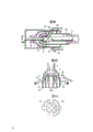
图1是一张根据本发明的充气型气体断路器的第一实施例纵断面视图,示出气体断路器的一种合闸状态;Fig. 1 is a longitudinal sectional view of the first embodiment of a gas-filled gas circuit breaker according to the present invention, showing a closed state of the gas circuit breaker;
图2是第一实施例的一张纵断面图,示出断路操作的中间阶段;Figure 2 is a longitudinal sectional view of the first embodiment, showing an intermediate stage of the breaking operation;
图3是一张第一实施例的纵断面图,示出断路操作的最终阶段;Figure 3 is a longitudinal sectional view of the first embodiment, showing the final stage of the breaking operation;
图4是一张表示第一实施例和一种常规的充气型气体断路器的压力提升特性图;Fig. 4 is a graph showing the pressure rise characteristics of the first embodiment and a conventional gas-filled type gas circuit breaker;
图5和6是一个本发明的充气型气体断路器的主要部分的放大断面图,示出第一和第二绝缘喷咀。5 and 6 are enlarged sectional views of a main part of a gas-filled type gas circuit breaker of the present invention, showing first and second insulating nozzles.
图7是一张根据本发明的一个充气型气体断路器第二种实施例的纵断面图,示出气体断路器的一种合闸状态;Fig. 7 is a longitudinal sectional view of a second embodiment of an inflatable gas circuit breaker according to the present invention, showing a closed state of the gas circuit breaker;
图8是一张该第二实施例的一种改形的纵断面图;Fig. 8 is a longitudinal sectional view of a modification of the second embodiment;
图9是一张根据本发明的一个气体断路器第三实施例的纵断面图,示出该气体断路器的一种合闸状态;Fig. 9 is a longitudinal sectional view of a third embodiment of a gas circuit breaker according to the present invention, showing a closed state of the gas circuit breaker;
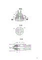
图10是一张第一和第二绝缘喷咀的断面图;Fig. 10 is a sectional view of a first and a second insulating nozzle;
图11是一张沿图10Ⅺ-Ⅺ线的断面图;Fig. 11 is a sectional view along line XI-XI of Fig. 10;
图12是相似于图10的一张视图,但示出改进了的第一和第二绝缘喷咀;Figure 12 is a view similar to Figure 10, but showing improved first and second insulating nozzles;
图13是一张取身图12的ⅩⅢ-ⅩⅢ线的断面图;以及Figure 13 is a sectional view taken along line XIII-XIII of Figure 12; and
图14是一张常规的充气型气体断路器的纵断面图。Fig. 14 is a longitudinal sectional view of a conventional gas filled type gas circuit breaker.
现在参考图1至4,叙述根据本发明的一种充气型气体断路器的第一个实施例。Referring now to FIGS. 1 to 4, a first embodiment of a gas charging type gas circuit breaker according to the present invention will be described.
一个灭弧气体充灌在该充气型气体断路器的内部一个可动触头2与固定触头1相对地设置,以便与固定触头接触,且由一个驱动轴11载着该可动触头2,在可动触头2的远离固定触头1那侧上设有一个固定活塞12,并驱动轴11可滑动地通过固定活塞12伸出,驱动轴11由一个操作机构(未示出)驱动作轴向移动,以驱动可动触头2朝向和远离固定触头1。充气圆筒13可滑动地装在固定活塞12上并与驱动轴11相连,充气圆筒13与固定活塞12相配合,以在充气圆筒13内构成充气室7,一个外圆筒15装在充气圆筒13的外圆周上,该圆筒的一端与充气圆筒外圆周表面封装,另一端与一个第二绝缘喷咀6相连,在外园筒和充气园筒之间形成热充气室(8)。在可动触头2的外表面上设置了一个外套19,以覆盖住可动触头2的外表面,且一个第一绝缘喷咀5与该充气圆筒13相连相对于
外套19呈环绕状。该第一绝缘喷咀构成一个第一气流通道,用于将灭弧气体从充气室7引导到一个电弧发生段,一个第二绝缘喷咀6与外圆筒15相连,相对于第一绝缘喷咀5呈环绕状。该第二绝缘喷咀6构成一个第二气流通道,用于将灭弧气体从热充气室8引导到电弧发生段。An arc extinguishing gas is filled inside the gas-filled gas circuit breaker. A
如果需要,可以围绕该固定触头1设一个主固定触头3,在上面这种情况,外圆筒15用作为主可动触头,使之与主固定触头3接触,从而供给主电流。If necessary, a main fixed contact 3 can be provided around the fixed
在如图1中所示的合闸状态时,该充气室7和该热充气室8处于非压缩状态,而在这些室8和7中充灌着额定压力的灭弧气体。In the closed state as shown in FIG. 1, the
当驱动轴11由操作机构(未示出)以这些图中所示的向右驱动时,该可动触头2移动离开该固定触头1,于是在这两个触头(图2)之间产生电弧16。当驱动轴11如此移动时,充气圆筒13也与驱动轴11一起移动,以致在充气室7中的灭弧气体被压缩成高压力,与此同时,围绕电弧16的灭弧气体由固定触头1和可动触头2之间产生的电弧16的热能所加热,从而朝向热充气室8产生一股气流,结果在热充气室8中的压力升到一个高的水平,在此时,加热了的那部分灭弧气体也流进充气室7,然而,由于充气室7的容积是调定到切断中、小电流有效的那样一个相对小的值,所以经过充气圆筒13作用在操作机构上的反作用力是小的,因此不会发生任何不良影响。When the drive shaft 11 is driven by the operating mechanism (not shown) to the right as shown in these figures, the
当遮断操作进一步进行下去达到和图3中的最后阶段时,固定触头1离开了第二绝缘喷咀6的喉部,此时,随着使触头彼此断开的驱动轴11的移动而升到高压的灭弧气体从充气室7馈入,并通过第一气流通道18a吹到电弧16上。另外,由电弧16的热能加热且升到高压的灭弧气体由热充气室8馈入并吹到电弧16上,结果,实现了灭弧操作。When the breaking operation was further carried out and reached the final stage in Fig. 3, the
在图4中同时示出充气室7和热充气室8中的灭弧气体的压力提升特性,与热充气室8相通的第二气流通道18b比与充气室7相通的第一气流通道18a设置得更靠近固定触头1,因此,在第二气流通道18b中的灭弧气体与电弧16实现接触的时刻晚于第一气流通道18a中的灭弧气体与电弧16实现接触的时刻,结果,热充气室8中的压力8p的增大晚于充气室7中的压力7p,随着时间的消逝,该热充气室8中的压力变得高于充气室7中的压力,且达到需在电流断开点B(破折线)断开电流时所需要的水平。另一方面,该充气室7中的压力7p被充气圆筒13的压缩操作和电弧16的热能以脉动方式增加,达到所需要的水平,正如图4所示,该压力的增大比图14中所示的常规充气型气体断路器所达到的要高,其原因是能被用于压缩的充气室空间尽管热充气室的容积增大而并不减小。In Fig. 4, the pressure rise characteristics of the arc extinguishing gas in the
正如上述,在本发明的充气型气体断路器中,充气室7和热充气室8是互相独立设置的,因此,该充气室7和热充气室8的容积
可以任意设定。换言之,该气体断路器的电流断开性能可以任意设定。另外,即使热充气室8的容积增加以应付切断大电流,可以用于压缩的充气室7空间也不减小,因此可以增强电流切断性能,而不降低充气室7的压力增加特性。再则,由于充气室7的容积和尤其它的承压面积不变,所以切断电流的操作力也不增大。As mentioned above, in the gas-filled gas circuit breaker of the present invention, the gas-filled
接着,参考图5,现在将详细地介绍用于将灭弧气体从充气室7引导到电弧发生部分的第一气流通道18a,以及用于将灭弧气体从热充气室8引导到电弧发生部分的第二气流通道18b。Next, with reference to FIG. 5 , the first
如图5所示,最好在固定触头1的轴向第一气流通道18a的距离L1小于第二气流通道18b在固定触头1的轴向的距离L2,当触头周围的灭弧气体被电弧16加热且加压时,产生方向朝着充气室7和热充气室8的灭弧气体流,通过让第一气流通道18a的距离L1小于第二气流通道18b的距离L2,可以减小朝向充气室7的灭弧气体流。换言之,可以减小电弧对充气室7的压力影响,因此也可以减小对驱动轴的操作力的影响。As shown in Fig. 5, it is preferable that the distance L1 of the first
如图6中所示,该第一绝缘喷咀5和第二绝缘喷咀6分别具有它的喉部5a和6a环绕着固定触头1,在可动触头2离开固定触头1的时刻到喉部5a向外移动离开固定触头1时的短暂期间中,如果喉部5a的直径D1大于喉部6a的直径D2,由电弧16加热和加压后的灭弧气体也通过第一绝缘咀5的喉部5a流到热充气室8,然而,即使在这种暂态工况中,可以减小对充气室的影响,因此,喉
部5a的直径D1以大于喉管段6a的直径D2为好。As shown in FIG. 6, the first insulating
现在参考图7将叙述根据本发明的一种充气型气体断路器的第二个实施例。在这个第二实施例中,通过充气圆筒13的周壁上形成有多个小孔17,而充气室7和热充气室8通过这些小孔17彼此相通。除了这个结构外,该第二个实施例在结构上与第一个实施例相同。Referring now to FIG. 7, a second embodiment of a gas charging type gas circuit breaker according to the present invention will be described. In this second embodiment, a plurality of
在上面介绍的暂态工况中,电弧16周围的灭弧气体被加热和加压,且流入充气室7。另一方面,热充气室8至此一直未被电弧16加热和加压,因此处于一种相对低的压力状况,从而使流进充气室7中的灭弧气体通过小孔17流进热充气室8。由此可减小电弧对充气室7的影响,也能减小对驱动轴的操作力的影响。In the transient conditions described above, the quenching gas around the
图8示出第二实施例的一种改形,在此改形中,在热充气室8中没有多个冷却翼片21,各翼片靠近各小孔17,它们使通过各小孔17流进热充气室8中的灭弧气体得到冷却。Figure 8 shows a modification of the second embodiment, in which there are no cooling
当切断某些事故产生的不平衡电流时,产生的电弧呈高强度,因此,电弧周围的灭弧气体被电弧加热到很高温度并流入该热充气室8中,于是流入热充气室8中的非常高温度的灭弧气体被各冷却翼片21冷却到适当温度,这将防止该热充气室8中的灭弧气体因为高温而分解,从而避免了灭弧气丧失灭弧特性。When the unbalanced current generated by some accidents is cut off, the arc generated is of high intensity, so the arc extinguishing gas around the arc is heated to a very high temperature by the arc and flows into the
图9示出根据本发明的充气型气体断路器的第三个实施例,在这个第三实施例中,驱动轴11差不多是实心的,且设有多个排气通
道10(图9中只示出一个排气通道)使可动触头2与外圆筒体15的外部相通。在排气通道10的出口14处设有一个排气导管20,当断路器处于合闸状态时,排气导管20将出口14封闭,而在第二绝缘喷咀6的喉部离开固定触头1时打开该出口。Figure 9 shows a third embodiment of a gas-filled gas circuit breaker according to the invention, in this third embodiment the drive shaft 11 is almost solid and provided with a plurality of exhaust vents.
The passage 10 (only one exhaust passage is shown in FIG. 9 ) communicates the
在图14的常规充气型气体断路器和本发明第一和第二实施例的充气型气体断路器中,用于熄弧并通过可动触头2内部的灭弧气体通过在驱动轴11内部构成的一个排气通道排出。然而在第三实施例中,通过可动触头2内部的灭弧气体从许多排气通道10排出,与驱动轴中的排气通道相比,排气通道10较短,而这些排气通道10的总流动面积更大,从而减小了由排气通道10产生的流动阻力而增强了排气效率。另外,由于驱动轴11是实心的,因为它的强度增大,可以减小驱动轴11的直径,从而断路器的总直径可被减小。In the conventional gas-filled gas circuit breaker of FIG. 14 and the gas-filled gas circuit breakers of the first and second embodiments of the present invention, the arc-extinguishing gas used for extinguishing the arc and passing through the inside of the
下面将叙述第一和第二绝缘喷咀。The first and second insulating nozzles will be described below.
参考图10,设有外套19以覆盖该可动触头2的外表面,并设有第一绝缘喷咀5以在外套19的外侧构成该第一气流通道18a。设有第二绝缘喷咀6以在第一绝缘喷咀5的外侧构成第二气流通道18b。该外套19有一个支柱段19a,而该第一绝缘喷咀以这样一种方式装配,即第一绝缘喷咀5的下端部安置在支柱段19a上,该第一绝缘喷咀5有一个支柱段5a,而该第二绝缘喷咀5以这种一种方式装配,即第二绝缘喷咀6的下端部安置在支柱段5a上。
该第二绝缘喷咀6用一个金属夹持器22紧固到外圆筒15上。在这种情况下,如图11中所示,必须使充气室7和第一气流通道18a连通的每个联络孔24相对于将热充气室8与第二气流通道6连通的联络孔25移位45°。Referring to FIG. 10 , a
随着上面的结构,外套19和第一及第二绝缘喷咀5和6仅可以用金属夹持件20固定,从而使组装简便。With the above structure, the
图12和13示出本发明的又一个实施例,在该实施例中,外套19、第一绝缘喷咀5和第二绝缘喷咀6为整体模铸成一个单元部件。Figures 12 and 13 show yet another embodiment of the present invention, in which the
由于以上结构,两喷咀互相间的位置变化减小,且可以确定电弧的发生位置。因此可以对灭弧气体吹到电弧上产生更正确的效果,从而增强了遮断效能,此外使组装简便。Due to the above structure, the mutual position variation of the two nozzles is reduced, and the occurrence position of the arc can be determined. Therefore, it is possible to produce a more correct effect on blowing of the arc extinguishing gas to the arc, thereby enhancing the interrupting performance, and furthermore, assembling is facilitated.
正如上述,在根据本发明的该充气型气体断路器中,热充气室是独立地在充气圆筒的外圆周上构成,因此,热充气室的容积可以根据遮断电流值任意调定,而不降低充气室的压力提升特性。As mentioned above, in the gas-filled gas circuit breaker according to the present invention, the hot gas-filled chamber is independently formed on the outer circumference of the gas-filled cylinder, so the volume of the hot-filled gas chamber can be adjusted arbitrarily according to the breaking current value without Reduced pressure boost characteristics of plenum chambers.
Claims (12)
Applications Claiming Priority (2)
| Application Number | Priority Date | Filing Date | Title |
|---|---|---|---|
| JP072075/91 | 1991-03-13 | ||
| JP3072075A JPH04284319A (en) | 1991-03-13 | 1991-03-13 | Gas-blast circuit breaker |
Publications (2)
| Publication Number | Publication Date |
|---|---|
| CN1064763A CN1064763A (en) | 1992-09-23 |
| CN1022877C true CN1022877C (en) | 1993-11-24 |
Family
ID=13478928
Family Applications (1)
| Application Number | Title | Priority Date | Filing Date |
|---|---|---|---|
| CN92101162A Expired - Fee Related CN1022877C (en) | 1991-03-13 | 1992-02-19 | Puffer-type gas circuit breaker |
Country Status (6)
| Country | Link |
|---|---|
| US (1) | US5229561A (en) |
| EP (1) | EP0503223B1 (en) |
| JP (1) | JPH04284319A (en) |
| KR (1) | KR100212820B1 (en) |
| CN (1) | CN1022877C (en) |
| DE (1) | DE69209551T2 (en) |
Families Citing this family (19)
| Publication number | Priority date | Publication date | Assignee | Title |
|---|---|---|---|---|
| FR2696041B1 (en) * | 1992-09-18 | 1994-10-14 | Alsthom Gec | Circuit breaker with elements fixed by hooping. |
| JP3281528B2 (en) * | 1996-02-09 | 2002-05-13 | 株式会社日立製作所 | Gas shut-off device |
| JP3876357B2 (en) * | 2002-01-09 | 2007-01-31 | 株式会社日立製作所 | Gas circuit breaker |
| DE10226044A1 (en) * | 2002-06-12 | 2003-12-24 | Alstom | Air blast switch |
| KR100770330B1 (en) * | 2006-04-26 | 2007-10-25 | 한국전기연구원 | Hybrid type gas interrupter with one united body of a puffer cylinder and a thermal-expansion chamber |
| DE102009009452A1 (en) * | 2009-02-13 | 2010-08-19 | Siemens Aktiengesellschaft | Switchgear assembly with a switching path |
| WO2013153110A1 (en) * | 2012-04-11 | 2013-10-17 | Abb Technology Ag | Circuit breaker |
| JP6320106B2 (en) * | 2014-03-25 | 2018-05-09 | 株式会社東芝 | Gas circuit breaker |
| US10364107B2 (en) | 2016-05-27 | 2019-07-30 | Richmond Engineering Works L.L.C. | Trunnion assembly for rotary dumper |
| CN105977073B (en) * | 2016-06-07 | 2018-07-06 | 平高集团有限公司 | Nozzle connection structure and the arc-chutes and breaker using the structure |
| EP3273463B1 (en) * | 2016-07-18 | 2019-08-28 | General Electric Technology GmbH | Electric switch provided with an arc-blasting unit |
| US10984973B2 (en) | 2017-07-31 | 2021-04-20 | General Electric Technology Gmbh | Electric switch provided with an arc-blasting unit |
| KR101968228B1 (en) * | 2017-12-28 | 2019-04-11 | 효성중공업 주식회사 | Circuit Breaker of moving conductor in a gas insulation switchgear |
| DE102018211621A1 (en) * | 2018-07-12 | 2020-01-16 | Siemens Aktiengesellschaft | Gas-insulated switch |
| JP6961105B2 (en) * | 2018-10-24 | 2021-11-05 | 三菱電機株式会社 | Gas circuit breaker |
| CN113330529B (en) * | 2019-03-19 | 2024-04-02 | 株式会社东芝 | Gas circuit breaker |
| CN109872919B (en) * | 2019-04-10 | 2020-11-03 | 西安西电开关电气有限公司 | Circuit breaker and arc extinguish chamber thereof |
| CN111863521B (en) * | 2020-06-11 | 2022-05-20 | 南方电网科学研究院有限责任公司 | SF6 quick circuit breaker |
| CN112289628B (en) * | 2020-10-20 | 2023-02-24 | 西安西电开关电气有限公司 | Arc extinguish chamber with double pressure expansion chambers |
Family Cites Families (9)
| Publication number | Priority date | Publication date | Assignee | Title |
|---|---|---|---|---|
| JPS5732451B2 (en) * | 1974-01-16 | 1982-07-10 | ||
| DE3265381D1 (en) * | 1981-06-12 | 1985-09-19 | Bbc Brown Boveri & Cie | High-voltage power circuit breaker |
| FR2519470A1 (en) * | 1982-01-05 | 1983-07-08 | Alsthom Atlantique | COMPRESSED GAS CIRCUIT BREAKER |
| JPS6231772A (en) * | 1985-07-31 | 1987-02-10 | Toyoda Gosei Co Ltd | Throttle shaping method of diaphragm |
| FR2596574B1 (en) * | 1986-04-01 | 1988-05-20 | Alsthom | HIGH VOLTAGE CIRCUIT BREAKER WITH DIELECTRIC GAS UNDER PRESSURE |
| JPH01243328A (en) * | 1988-03-25 | 1989-09-28 | Hitachi Ltd | Patshua type gas circuit breaker |
| JP2625983B2 (en) * | 1988-11-08 | 1997-07-02 | 株式会社明電舎 | Puffer type gas circuit breaker |
| US5079391A (en) * | 1989-11-11 | 1992-01-07 | Hitachi, Ltd. | Puffer type gas circuit breaker, contact cover and insulated nozzle of the breaker |
| JPH03171521A (en) * | 1989-11-29 | 1991-07-25 | Hitachi Ltd | gas circuit breaker |
-
1991
- 1991-03-13 JP JP3072075A patent/JPH04284319A/en active Pending
-
1992
- 1992-01-02 EP EP92100034A patent/EP0503223B1/en not_active Expired - Lifetime
- 1992-01-02 DE DE69209551T patent/DE69209551T2/en not_active Expired - Fee Related
- 1992-01-23 KR KR1019920000902A patent/KR100212820B1/en not_active Expired - Fee Related
- 1992-02-19 CN CN92101162A patent/CN1022877C/en not_active Expired - Fee Related
- 1992-02-20 US US07/838,335 patent/US5229561A/en not_active Expired - Fee Related
Also Published As
| Publication number | Publication date |
|---|---|
| CN1064763A (en) | 1992-09-23 |
| KR100212820B1 (en) | 1999-08-02 |
| DE69209551D1 (en) | 1996-05-09 |
| EP0503223A3 (en) | 1993-03-17 |
| EP0503223B1 (en) | 1996-04-03 |
| US5229561A (en) | 1993-07-20 |
| DE69209551T2 (en) | 1996-11-21 |
| KR920018795A (en) | 1992-10-22 |
| EP0503223A2 (en) | 1992-09-16 |
| JPH04284319A (en) | 1992-10-08 |
Similar Documents
| Publication | Publication Date | Title |
|---|---|---|
| CN1022877C (en) | Puffer-type gas circuit breaker | |
| CN1126132C (en) | Circuit breaker | |
| CN1077327C (en) | Buffer gas breaker | |
| CN1068136C (en) | Circuit breaker | |
| US20130168357A1 (en) | Puffer-type gas circuit-breaker | |
| CN1226073A (en) | gas circuit breaker | |
| HU192364B (en) | Gas pressure switch | |
| US6660954B2 (en) | Gas-blast circuit-breaker | |
| WO2024017046A1 (en) | Switch unit, isolation switch, and power supply system | |
| KR20220046124A (en) | Self-blast type gas circuit breaker | |
| US5072084A (en) | Gas circuit breaker | |
| JP2514030B2 (en) | Compressed dielectric gas high voltage circuit breaker | |
| US12347634B2 (en) | Circuit breaker comprising an improved gas flow management | |
| US4289942A (en) | Gas-blast circuit-interrupter with multiple insulating arc-shield construction | |
| JP6830363B2 (en) | Gas circuit breaker | |
| CN1016548B (en) | High-and medium-voltage gas circuit breakers | |
| CN112509860A (en) | Gas circuit breaker | |
| CN85107324A (en) | Air blow switch | |
| CN1231940C (en) | Collector and gas circuit breaker | |
| CN217813844U (en) | Air compressor | |
| JP7268660B2 (en) | gas circuit breaker | |
| JP2002075148A (en) | Puffer type gas circuit breaker | |
| US4246459A (en) | Gas circuit breaker | |
| CN1018490B (en) | Gas-blast load-break switch | |
| JP7612893B2 (en) | Gas Circuit Breaker |
Legal Events
| Date | Code | Title | Description |
|---|---|---|---|
| C10 | Entry into substantive examination | ||
| SE01 | Entry into force of request for substantive examination | ||
| C06 | Publication | ||
| PB01 | Publication | ||
| C14 | Grant of patent or utility model | ||
| GR01 | Patent grant | ||
| C19 | Lapse of patent right due to non-payment of the annual fee | ||
| CF01 | Termination of patent right due to non-payment of annual fee |