CN102575475A - Double floor structure and support leg for double floor structure - Google Patents
Double floor structure and support leg for double floor structure Download PDFInfo
- Publication number
- CN102575475A CN102575475A CN2010800345219A CN201080034521A CN102575475A CN 102575475 A CN102575475 A CN 102575475A CN 2010800345219 A CN2010800345219 A CN 2010800345219A CN 201080034521 A CN201080034521 A CN 201080034521A CN 102575475 A CN102575475 A CN 102575475A
- Authority
- CN
- China
- Prior art keywords
- mentioned
- pedestal
- parts
- double floor
- beam material
- Prior art date
- Legal status (The legal status is an assumption and is not a legal conclusion. Google has not performed a legal analysis and makes no representation as to the accuracy of the status listed.)
- Granted
Links
Images


Classifications
-
- E—FIXED CONSTRUCTIONS
- E04—BUILDING
- E04F—FINISHING WORK ON BUILDINGS, e.g. STAIRS, FLOORS
- E04F15/00—Flooring
- E04F15/02—Flooring or floor layers composed of a number of similar elements
- E04F15/024—Sectional false floors, e.g. computer floors
- E04F15/02447—Supporting structures
- E04F15/02458—Framework supporting the panels
-
- E—FIXED CONSTRUCTIONS
- E04—BUILDING
- E04F—FINISHING WORK ON BUILDINGS, e.g. STAIRS, FLOORS
- E04F15/00—Flooring
- E04F15/02—Flooring or floor layers composed of a number of similar elements
- E04F15/024—Sectional false floors, e.g. computer floors
- E04F15/02447—Supporting structures
- E04F15/02452—Details of junctions between the supporting structures and the panels or a panel-supporting framework
-
- E—FIXED CONSTRUCTIONS
- E04—BUILDING
- E04F—FINISHING WORK ON BUILDINGS, e.g. STAIRS, FLOORS
- E04F15/00—Flooring
- E04F15/02—Flooring or floor layers composed of a number of similar elements
- E04F15/024—Sectional false floors, e.g. computer floors
- E04F15/02447—Supporting structures
- E04F15/02464—Height adjustable elements for supporting the panels or a panel-supporting framework
Landscapes
- Engineering & Computer Science (AREA)
- Architecture (AREA)
- General Engineering & Computer Science (AREA)
- Civil Engineering (AREA)
- Structural Engineering (AREA)
- Floor Finish (AREA)
Abstract
课题是提供一种能够以低成本对应施工条件及需求者的需求的双层地板构造。一种具备设置在下层地板上的多个支承脚(1)、和用来构成上层地板的多列梁材的双层地板构造(K),其特征在于,支承脚(1)具备从下侧支承梁材的上部件(14)、从下侧支承上部件(14)的中部件(13)、和从下侧支承中部件(13)的下部件(12);上部件(14)、中部件(13)及下部件(12)都由金属制的挤压型材构成,并且配置为,使其挤压方向为上下方向。
The subject matter is to provide a double-layer floor structure that can meet the construction conditions and user needs at a low cost. A double-layer floor structure (K) having multiple support feet (1) set on the lower floor and multiple rows of beams for forming the upper floor is characterized in that the support feet (1) have an upper part (14) that supports the beams from the lower side, a middle part (13) that supports the upper part (14) from the lower side, and a lower part (12) that supports the middle part (13) from the lower side; the upper part (14), the middle part (13) and the lower part (12) are all made of extruded metal profiles and are configured such that their extrusion direction is vertical.
Description
技术领域 technical field
本发明涉及双层地板构造,还涉及在构建双层地板时使用的双层地板用支承脚。 The present invention relates to double floor construction, and also relates to a support foot for a double floor used when constructing a double floor.
背景技术 Background technique
在专利文献1中,公开了一种双层地板构造,是在设置于下层地板上的多个支承脚上架设梁材(上层地板构成件)而成的双层地板构造,支承脚由铝合金制的挤压型材构成。专利文献1的支承脚是将由铝合金制的挤压型材构成的上部件、中部件及下部件组合而形成的。如果使用该支承脚构建双层地板构造,则能够以低成本对应于施工条件及需求者的各种要求。
In
专利文献1:特开2009-150088号公报。 Patent Document 1: JP-A-2009-150088.
发明内容 Contents of the invention
在专利文献1的技术中,由于支承双层地板的梁材的上部件的挤压方向与梁材的挤压方向平行,所以与配置为使挤压方向为上下方向的中部件及下部件垂直地交叉。因此,上部件的刚性依存于该挤压型材的截面形状,需要按照施工条件及需求者的各种要求设计挤压型材的截面形状。
In the technology of
所以,本发明的课题是提供一种能够以低成本对应于施工条件及需求者的需求的双层地板构造及双层地板用支承脚。 Therefore, an object of the present invention is to provide a double-floor structure and a support foot for a double-floor that can respond to construction conditions and needs of consumers at low cost.
解决这样的课题的有关本发明的双层地板构造,是具备设置在下层地板上的多个支承脚、和用来构成上层地板的多列梁材的双层地板构造,其特征在于,上述支承脚具备从下侧支承上述梁材的上部件、配置在上述上部件的下方的下部件、和夹设在上述上部件与上述下部件之间的中部件;上述上部件、上述中部件及上述下部件都由金属制的挤压型材构成,并且配置为,使其挤压方向为上下方向。 The double floor structure of the present invention which solves such problems is a double floor structure provided with a plurality of supporting feet provided on the lower floor and a plurality of rows of beams for constituting the upper floor, and is characterized in that the support The leg includes an upper member supporting the beam from below, a lower member disposed below the upper member, and a middle member interposed between the upper member and the lower member; the upper member, the middle member, and the The lower members are all made of metal extruded profiles, and are arranged so that the extrusion direction is the up-down direction.
根据本发明,通过变更作为上部件的坯材的挤压型材的切断长度,能够变更上部件的刚性,所以能够容易地调整双层地板构造的最大装载载荷及耐震性能。另外,挤压型材优选的是由铝合金构成,但只要能够挤压成形,也可以由其他金属构成。 According to the present invention, since the rigidity of the upper member can be changed by changing the cutting length of the extruded profile as the base material of the upper member, the maximum loading load and shock resistance of the double floor structure can be easily adjusted. In addition, the extruded profile is preferably made of aluminum alloy, but it may be made of other metals as long as it can be extruded.
优选的是,将上述中部件的上部插入到上述上部件中,将上述中部件的下部插入到上述下部件中。如果这样,则将上部件固定到中部件上时的定位变得容易,并且将下部件固定到中部件上时的定位变得容易。 Preferably, the upper portion of the middle member is inserted into the upper member, and the lower portion of the middle member is inserted into the lower member. This facilitates positioning when fixing the upper member to the middle member, and facilitates positioning when fixing the lower member to the middle member.
在梁材与上部件的连结方法中没有限制,例如可以利用螺栓、螺母连结。在此情况下,优选的是,在上述梁材的下表面上,形成有沿上述梁材的长度方向延伸的卡止槽;通过将插通在上述上部件中的螺栓的轴部拧合到收容在上述卡止槽中的螺母中、或将头部收容在上述卡止槽中的螺栓的轴部拧合到配置在上述上部件的下侧的螺母中,将上述上部件固定到上述梁材上。如果利用“卡止槽”,则能够将支承脚固定到梁材的长度方向的任意的位置上,所以能够容易地增减支承脚的设置间隔,进而,能够容易地调整双层地板构造的最大装载载荷及耐震性能。 There is no limitation on the method of connecting the beam and the upper member, for example, bolts and nuts may be used for connection. In this case, it is preferable that, on the lower surface of the above-mentioned beam material, a locking groove extending along the length direction of the above-mentioned beam material is formed; The nuts accommodated in the locking grooves, or the shafts of the bolts whose heads are accommodated in the locking grooves are screwed into the nuts arranged on the lower side of the upper member to fix the upper member to the beam. on the material. If the "locking groove" is used, the supporting legs can be fixed to any position in the longitudinal direction of the beam, so the installation interval of the supporting legs can be easily increased or decreased, and the maximum height of the double floor structure can be easily adjusted. load and shock resistance.
在本发明中,也可以具备将相邻的梁材彼此连接的连结部件。如果这样,则成为将支承相邻的两个梁材中的一个的支承脚和支承另一个的支承脚经由两梁材及连结部件连结,所以能够得到刚性较高的双层地板构造。 In this invention, you may provide the connection member which connects adjacent beam members. In this way, the support leg supporting one of the adjacent two beams and the support leg supporting the other are connected via both beams and the connecting member, so that a highly rigid double-floor structure can be obtained.
在将连结部件固定到梁材上的情况下,优选的是利用形成在梁材的下表面上的卡止槽。即,优选的是,通过将插通在上述连结部件中的螺栓的轴部拧合到收容在上述卡止槽中的螺母中、或将头部收容在上述卡止槽中的螺栓的轴部拧合到配置在上述连结部件的下侧的螺母中,将上述连结部件固定到上述梁材上。如果这样,则能够将连结部件固定到梁材的长度方向的任意的位置上。 When fixing the connecting member to the girder, it is preferable to use the locking groove formed on the lower surface of the girder. That is, it is preferable to screw the shaft portion of the bolt inserted into the connecting member into the nut accommodated in the locking groove, or the shaft portion of the bolt whose head is accommodated in the locking groove. It is screwed into the nut arranged on the lower side of the said connection member, and the said connection member is fixed to the said beam material. In this way, the connection member can be fixed to an arbitrary position in the longitudinal direction of the girder.
另外,在形成设备类设置用的双层地板构造的情况下,优选的是,将多列梁材配置在设备类的下侧,并且具备作为上述设备类的台座的台座部件。在此情况下,优选的是,在上述梁材的上表面上,形成沿上述梁材的长度方向延伸的多条台座安装槽,利用至少两条上述台座安装槽将上述台座部件固定到上述梁材上。如果这样,则能够将台座部件固定到梁材的长度方向的任意的位置上。 In addition, when forming a double-floor structure for installation of equipment, it is preferable to arrange beams in multiple rows on the lower side of the equipment and to include a pedestal member as a pedestal for the equipment. In this case, preferably, on the upper surface of the beam, a plurality of pedestal mounting grooves extending in the longitudinal direction of the beam are formed, and the pedestal member is fixed to the beam by at least two of the pedestal mounting grooves. on the material. In this way, the pedestal member can be fixed to an arbitrary position in the longitudinal direction of the beam.
在梁材与设备类之间夹设台座部件的情况下,优选的是,在上述台座部件上设有螺栓收容部,所述螺栓收容部收容用来将上述设备类固定到上述台座上的设备固定螺栓的头部;在上述螺栓收容部的上壁上,形成能够插通上述设备固定螺栓的轴部的多个设备固定孔、或者形成能够插通上述设备固定螺栓的轴部的长短两个长孔。如果这样,则即使是形成在设备类上的螺栓插通孔等的间距按照设备类而不同那样的情况,也能够容易地对应。 When a pedestal member is interposed between beams and equipment, it is preferable that the pedestal member is provided with a bolt accommodating portion for accommodating equipment for fixing the equipment to the pedestal. The head of the fixing bolt; on the upper wall of the above-mentioned bolt receiving part, a plurality of equipment fixing holes that can be inserted through the shaft of the equipment fixing bolt are formed, or two lengths of the shaft that can be inserted through the above-mentioned equipment fixing bolt are formed. Long hole. In this way, even when the pitches of the bolt insertion holes and the like formed in the devices differ depending on the devices, it can be easily handled.
在上述螺栓收容部的上壁上形成有多个设备固定孔的情况下,优选的是,设定上述设备固定孔的位置,以使使上述台座部件在水平面内反转时的上述设备固定孔的排列与反转前的排列不同。如果这样,则能够对应于更多的设备类。 In the case where a plurality of equipment fixing holes are formed on the upper wall of the bolt receiving portion, it is preferable to set the positions of the equipment fixing holes so that the equipment fixing holes when the above-mentioned pedestal member is reversed in the horizontal plane The arrangement of is different from the arrangement before inversion. In this way, more device classes can be supported.
也可以是,除了台座部件以外,还具备将上述设备类的重量传递给上述梁材的辅助部件。在此情况下,上述辅助部件优选的是跨越上述台座部件而配置。如果这样,则能够稳定地支承设备类。 In addition to the pedestal member, an auxiliary member for transmitting the weight of the above-mentioned equipment to the above-mentioned beam may be further provided. In this case, it is preferable that the said auxiliary member is arrange|positioned over the said pedestal member. In this way, devices can be stably supported.
也可以在上述设备类的未设置区域中配置填塞镶板。如果这样,则在使用来将设备类冷却的调和空气通流到地板下空间(上层地板与下层地板之间的空间)中的情况下,防止调和空气的散逸,所以能够将设备类效率良好地冷却。另外,上述填塞镶板优选的是以能够拆卸的状态覆盖设置在相邻的梁材间。如果这样,则在未设置区域中设置新的设备类的情况下的对应变得容易。 Infill panels can also be configured in unset areas of the above equipment classes. In this way, when the conditioned air used to cool the equipment is circulated into the underfloor space (the space between the upper floor and the lower floor), the conditioned air is prevented from escaping, so the equipment can be efficiently distributed. cool down. Moreover, it is preferable that the said caulking panel is covered and installed between the adjacent girders in the state detachable. This facilitates correspondence when a new device class is set in an unset area.
解决上述课题的有关本发明的双层地板用支承脚,是在构建双层地板时设置在下层地板上的双层地板用支承脚,其特征在于,具备:上部件,从下侧支承用来构成上层地板的上层地板构造体;下部件,配置在上述上部件的下方;中部件,夹设在上述上部件与上述下部件之间;上述上部件、上述中部件及上述下部件都由金属制的挤压型材构成,并且配置为,使其挤压方向为上下方向。 The supporting foot for a double floor of the present invention that solves the above-mentioned problems is a supporting foot for a double floor that is installed on a lower floor when a double floor is constructed, and is characterized in that it includes an upper member that is supported from the lower side for The upper floor structure constituting the upper floor; the lower member is disposed below the upper member; the middle member is interposed between the upper member and the lower member; the upper member, the middle member, and the lower member are all made of metal Made of extruded profiles, and configured so that the extruded direction is the up and down direction.
根据有关本发明的双层地板用支承脚,仅通过变更作为上部件、中部件或下部件的坯材的挤压型材的切断长度,就能够变更高度尺寸,所以能够容易地变更地板下空间的高度尺寸,进而能够以低成本对应于施工条件及需求者的需求。另外,在能够通过双层地板用支承脚支承的上层地板构成件中,不仅是梁材,还包括地板镶板等面状的部件。挤压型材优选的是由铝合金构成,但只要能够挤压成形,也可以由其他金属构成。 According to the supporting foot for a double floor according to the present invention, the height dimension can be changed only by changing the cut length of the extruded section material of the billet as the upper part, the middle part or the lower part, so the size of the underfloor space can be easily changed. The height dimension, and thus can correspond to the construction conditions and the needs of the demander at a low cost. In addition, the upper floor structure that can be supported by the supporting legs of the double floor includes not only beams but also planar members such as floor panels. The extruded profile is preferably made of aluminum alloy, but may be made of other metals as long as it can be extruded.
在中部件的截面形状等中没有限制,但优选的是使用呈圆筒状的中部件。如果这样,则在使设备类冷却用的调和空气通流到地板下空间中的情况下,调和空气的流动变得平顺,所以能够将设备类效率良好地冷却。此外,如果使中部件为圆筒状,则在中部件的外周面上不再存在突起等(即,中部件的外周面为容易适应于电缆的形状),所以将配线在地板下的电缆损伤的可能性变低,进而能够顺利地进行配线作业。此外,由于在中部件的形状中没有方向性,所以容易吸收制作上的误差。 There is no limitation in the cross-sectional shape and the like of the middle member, but it is preferable to use a cylindrical middle member. In this way, when the conditioned air for cooling the equipment is circulated into the underfloor space, the flow of the conditioned air becomes smooth, so that the equipment can be efficiently cooled. In addition, if the middle part is made into a cylindrical shape, there are no protrusions etc. on the outer peripheral surface of the middle part (that is, the outer peripheral surface of the middle part is a shape that is easy to adapt to the cable), so the cables that are wired under the floor The possibility of damage is reduced, and wiring work can be performed smoothly. In addition, since there is no directionality in the shape of the middle part, manufacturing errors are easily absorbed.
在上部件、中部件及下部件的接合方法中没有限制,但优选的是,将上述上部件与上述中部件通过焊接接合,并且将上述中部件与上述下部件通过焊接接合。在螺栓接合的情况下,需要对各部件的开孔加工或螺栓紧固作业等,但如果通过焊接接合,则能够将这样的作业省略。 There is no limitation on the joining method of the upper member, the middle member, and the lower member, but it is preferable to join the upper member and the middle member by welding, and join the middle member and the lower member by welding. In the case of bolt joining, drilling of each member, bolt fastening work, and the like are required, but such work can be omitted when joining by welding.
优选的是,在上述中部件的侧壁上形成阴螺纹。如果这样,则能够将任选类(例如用来将配线或配管固定的电缆槽或夹具等)容易地固定。 Preferably, a female thread is formed on the side wall of the above-mentioned middle member. In this way, optional items (for example, cable ducts, clamps, and the like for fixing wiring and piping) can be easily fixed.
根据有关本发明的双层地板构造及双层地板用支承脚,能够以低成本对应于施工条件及需求者的需求。 According to the double-floor structure and the supporting foot for double-floor according to the present invention, it is possible to respond to construction conditions and needs of customers at low cost.
附图说明 Description of drawings
图1是表示包括有关本发明的实施方式的双层地板构造的双层地板的立体图。 Fig. 1 is a perspective view showing a double floor including a double floor structure according to an embodiment of the present invention.
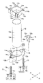
图2是有关本发明的实施方式的支承脚的主视图。 Fig. 2 is a front view of the support leg according to the embodiment of the present invention.
图3是有关本发明的实施方式的支承脚的分解立体图。 Fig. 3 is an exploded perspective view of the support leg according to the embodiment of the present invention.
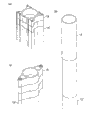
图4是说明构成支承脚的部件的制造方法的立体图,图4(a)是表示上部件的制造方法的图,图4(b)是表示中部件的制造方法的图,图4(c)是表示下部件的制造方法的图。 Fig. 4 is a perspective view illustrating a method of manufacturing a member constituting a supporting leg, Fig. 4(a) is a diagram showing a method of manufacturing an upper member, Fig. 4(b) is a diagram showing a method of manufacturing a middle member, Fig. 4(c) It is a figure which shows the manufacturing method of a lower part.
图5是有关本发明的实施方式的支承脚的剖视图。 Fig. 5 is a cross-sectional view of the support leg according to the embodiment of the present invention.
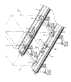
图6是表示将有关本发明的实施方式的双层地板构造的一部分分解的状态的立体图。 Fig. 6 is a perspective view showing a partially disassembled state of the double floor structure according to the embodiment of the present invention.
图7(a)是第一台座部件的立体图,图7(b)是第一台座部件的俯视图。 FIG. 7( a ) is a perspective view of the first pedestal member, and FIG. 7( b ) is a plan view of the first pedestal member.
图8(a)是第二台座部件的立体图,图7(b)是第二台座部件的俯视图。 FIG. 8( a ) is a perspective view of the second pedestal member, and FIG. 7( b ) is a plan view of the second pedestal member.
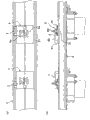
图9是表示从下侧观察有关本发明的实施方式的双层地板构造的状态的立体图。 Fig. 9 is a perspective view showing a state in which the double-floor structure according to the embodiment of the present invention is viewed from below.
图10是表示有关本发明的实施方式的双层地板构造的变形例的立体图。 Fig. 10 is a perspective view showing a modified example of the double floor structure according to the embodiment of the present invention.
图11(a)是其侧视图,图11(b)是其俯视图。 Fig. 11(a) is its side view, and Fig. 11(b) is its top view.
图12(a)是辅助部件的俯视图,图12(b)是表示使辅助部件反转的状态的俯视图。 FIG. 12( a ) is a plan view of the auxiliary member, and FIG. 12( b ) is a plan view showing a state in which the auxiliary member is reversed.
具体实施方式 Detailed ways
图1所示的双层地板F是构建在数据中心等的下层地板(水泥地板)S上的,具备设置设备类C的设备设置区域F1、和相邻于该设备设置区域F1而形成的通路区域F2。另外,在设备类C的种类、大小、规格等中没有限制。在设备类C中,不仅是通信设备或电子计算机这种仪器设备本身,还包括收纳它们的收纳架。 The double floor F shown in Fig. 1 is built on the lower floor (concrete floor) S of a data center, etc., and has an equipment installation area F1 where equipment C is installed, and a passage formed adjacent to the equipment installation area F1 Area F2. In addition, there is no limitation in the type, size, specification, etc. of the device class C. In equipment category C, not only the equipment itself such as communication equipment or electronic computer, but also the storage racks for storing them.
设备设置区域F1由有关本发明的实施方式的双层地板构造K形成,通路区域F2利用铺设在相邻的双层地板构造K、K间的多个地板镶板P2、P2、……形成。即使是设备设置区域F1,也在没有设置设备类C的区域(未设置区域)中铺设有填塞镶板P1。调和空气流通到地板下空间中,通过从地板下空间吹起的调和空气将设备类C冷却。 The equipment installation area F1 is formed by the double-floor structure K according to the embodiment of the present invention, and the passage area F2 is formed by a plurality of floor panels P2, P2, . . . laid between adjacent double-floor structures K, K. Even in the facility installation area F1, the infill panel P1 is laid in the area (uninstalled area) where the facility category C is not installed. The conditioned air is circulated into the underfloor space, and the equipment class C is cooled by the conditioned air blown from the underfloor space.
双层地板构造K具备设置在下层地板S上的多个支承脚1、1、……、用来构成上层地板的两列梁材2、2、作为设备类C的台座的第一台座部件3、3、……及第二台座部件4、4、……、和将相邻的梁材2、2间接地连接的连结部件5。另外,以下的说明中的“前”、“后”是以梁材2的长度方向为基准、将梁材2的长度方向作为“前后方向”。
The double floor structure K includes a plurality of
首先,详细地说明支承脚1的结构。
First, the structure of the supporting
支承脚1具备立设在下层地板S上的一对脚部11、11、架设在该脚部11、11上的下部件12、支承在该下部件12上的中部件13、支承在该中部件13上的上部件14、和安装在下部件12上的保护盖15(参照图3)。
The
脚部11如图2所示,具备固定在下层地板S上的基础板11a、立设在该基础板11a上的柱部11b、和在夹着下部件12的状态下拧合在柱部11b的阳螺纹上的下螺母11c及上螺母11d。基础板11a通过从其上表面侧打入到下层地板S中的锚螺栓S1固定在下层地板S的上表面上。
As shown in FIG. 2, the
下部件12是从下侧支承中部件13的部件,配置在上部件14的下方。本实施方式的下部件12在从下层地板S浮起的状态下支承在脚部11、11上。如图3所示,下部件12由截面中空的铝合金制的挤压型材构成,配置为,使其挤压方向为上下方向。即,下部件12以作为其坯材的挤压型材的中空部在上下表面上开口那样的朝向(即,中空部在上下方向上连续那样的朝向)配置。为了制造下部件12,如图4(c)所示,只要将具有与下部件12的平面形状相同的截面形状的挤压型材12′沿着与挤压方向正交的面(在图4(c)中为水平面)切断就可以。
The
如图3所示,本实施方式的下部件12具备接合在中部件13上的框部12a、连接在脚部11上的脚连接部12b、和将框部12a与脚连接部12b连接的肋12c。
As shown in FIG. 3 , the
框部12a具备与中部件13对应的形状。本实施方式的框部12a对应于呈圆筒状的中部件13而呈圆筒状。在框部12a的内空中,插入着中部件13的下部。框部12a的内径比中部件13的外径稍大。
The
脚连接部12b配置在框部12a的左右两侧。对于脚连接部12b的形态并没有限制,但本实施方式的形态呈筒状。在脚连接部12b的内空中,插通着脚部11的柱部11b。另外,脚连接部12b的内空(孔)既可以在将作为下部件12的坯材的挤压型材12′(参照图4(c))挤压成形时成形,也可以在挤压成形后实施开孔加工而形成。此外,脚连接部12b不需要是闭截面,只要是能够插通柱部11b的形态,也可以是开截面(例如,截面C字状等)。
The
肋12c从框部12a朝向侧方伸出。在本实施方式的肋12c中,形成有在上下方向上连续的中空部。
The
为了将下部件12固定在脚部11上,首先,在脚部11的柱部11b上拧合下螺母11c。接着,在下部件12的脚连接部12b中插通柱部11b,将脚连接部12b载置到下螺母11c上。然后,只要在柱部11b上拧合上螺母11d并拧紧就可以(参照图2)。另外,通过调节下螺母11c及上螺母11d的位置,能够将下部件12的高度位置微调,所以即使是在下层地板S的完成状态中存在不平整或倾斜等那样的情况,也能够容易地对应。
In order to fix the
中部件13如图2所示,是从下侧支承上部件14的部件,夹设在下部件12与上部件14之间。如图3所示,中部件13由截面中空的铝合金制的挤压型材构成,配置为,使其挤压方向为上下方向。即,中部件13以作为其坯材的挤压型材的中空部在上下表面上开口那样的朝向配置。为了制造中部件13,如图4(b)所示,只要将具有与中部件13的平面形状相同的截面形状的挤压型材13′沿着与挤压方向正交的面(在图4(b)中为水平面)切断就可以。
As shown in FIG. 2 , the
本实施方式的中部件13呈圆筒状。如图3所示,在中部件13的侧壁上,形成有阴螺纹13a、13a、……。在阴螺纹13a上,虽然省略了图示,但拧合着用来将任选类(例如用来将配线或配管固定的电缆槽或夹具等)固定的阳螺纹零件。
The
为了将中部件13与下部件12一体化,如图5所示,只要在将中部件13的下部插入在下部件12的框部12a中的状态下将两者通过焊接接合就可以。在本实施方式中,一边保持着使中部件13的下端面位于比下部件12的框部12a的下端面上升的位置上的状态、一边遍及中部件13的整周将框部12a的内周面与中部件13的下端面焊接(参照附图标记W1),进而,遍及中部件13的整周将框部12a的上端面与中部件13的外周面焊接(参照附图标记W2)。另外,在本实施方式中,例示了将下部件12与中部件13在上下两个部位(附加有附图标记W1、W2的部分)处焊接的情况,但也可以仅为某一方。此外,在本实施方式中,例示了遍及中部件13的整周焊接的情况,但也可以断续地焊接。
In order to integrate the
上部件14如图2所示,是从下侧支承梁材2的部件,夹设在中部件13与梁材2之间。如图3所示,上部件14由截面中空的铝合金制的挤压型材构成,配置为,使其挤压方向为上下方向。即,上部件14以作为其坯材的挤压型材的中空部在上下表面上开口那样的朝向配置。为了制造上部件14,如图4(a)所示,只要将具有与上部件14的平面形状相同的截面形状的挤压型材14′沿着与挤压方向正交的面(在图4(a)中是水平面)切断就可以。
As shown in FIG. 2 , the
本实施方式的上部件14如图3所示,具备与中部件13接合的框部14a、从框部14a以放射状伸出的多个伸出部14b、14b、……、和配置在框部14a的外侧的多个插通部14c、14c、……。
The
框部14a具备对应于中部件13的形状。本实施方式的框部14a对应于呈圆筒状的中部件14而呈圆筒状。在框部14a的内空中,插入着中部件13的上部。框部14a的内径比中部件13的外径稍大。
The
伸出部14b形成在框部14a的外周侧。在伸出部14b中,形成有在上下方向上连续的中空部。
The protruding
插通部14c是导引梁固定螺栓B1(参照图2)的轴部的部位,具备在上下方向上连续的中空部。在本实施方式中,在框部14a的左右两侧分别配置有四个插通部14c、14c、……,但左右两侧都配置在一直线上。本实施方式的插通部14c呈截面C字状,在插通部14c的侧面上,形成有在上下方向上连续的缝隙。使插通部14c为开截面是为了使作为其坯材的挤压型材的14′(参照图4(a))的制造变得容易。另外,插通部14c不需要是开截面,只要是能够插通螺栓的轴部的形状,也可以是闭截面。此外,插通部14c既可以在将作为上部件14的坯材的挤压型材14′(参照图4(a))挤压成形时成形,也可以在挤压成形后实施开孔加工而形成。
The
为了将上部件14与下部件12一体化,如图5所示,只要在将中部件13的上部插入到上部件14的框部14a中的状态下将两者通过焊接接合就可以。在本实施方式中,一边保持着使中部件13的上端面位于比上部件14的框部14a的上端面下降的位置上的状态,一边遍及中部件13的整周将中部件13的上端面与框部14a的内周面焊接(参照附图标记W3),进而,遍及中部件13的整周将中部件13的外周面与框部14a的下端面焊接(参照附图标记W4)。另外,在本实施方式中,例示了将中部件13与上部件14在上下两个部位(附加有附图标记W3、W4的部分)焊接的情况,但也可以仅为某一方。此外,在本实施方式中,例示了遍及中部件13的整周焊接的情况,但也可以断续地焊接。
In order to integrate
图3所示的保护盖15是将下部件12的边缘(下部件12的角部)的至少一部分遮盖的部件,由合成树脂制的部件构成。本实施方式的保护盖15具备插入到肋12c的中空部中的插入部15a、覆盖设置在肋12c的上表面上的盖部15b、和遮盖肋12c的边缘的边缘盖部15c、15c。边缘盖部15c的上表面成形为带有圆度的形状。下部件12是将挤压型材切断而形成的,所以肋12c的边缘有可能变得锐利,但只要由边缘盖部15c将边缘遮盖,就能够防止未图示的配线接触在边缘上,所以能够防止因边缘带来的配线的损伤。另外,在对下部件12的边缘部分实施倒角加工的情况、或采用用来防止配线的损伤的对策的情况下,也可以将保护盖15省略。顺便说一下,使用保护盖15与对下部件12的边缘部分实施倒角加工相比更便宜。
The
接着,详细地说明梁材2的结构。
Next, the structure of the
如图1所示,梁材2是用来构成上层地板的上层地板构成件的一种,在本实施方式中,构成设备设置区域F1的床面的一部分,并且承担支承覆盖设置在设备设置区域F1的未设置区域上的多个填塞镶板P1、P1、……及构成通路区域F2的地面的多个地板镶板P2、P2、……的作用。
As shown in FIG. 1 , the
梁材2跨越在前后方向上隔开间隔排列的多个(在本实施方式中是三个)支承脚1、1、……而配置。本实施方式的梁材2由截面中空的铝合金制的挤压型材构成。
The
如图6所示,在梁材2的下表面上,形成有沿梁材2的长度方向(挤压方向)延伸的多条(在本实施方式中是两条)卡止槽2a、2a,在梁材2的上表面上,形成有沿梁材2的长度方向(挤压方向)延伸的多条(在本实施方式中是三条)台座安装槽2b、2b、……。
As shown in FIG. 6, on the lower surface of the
在卡止槽2a中,收容着梁固定螺栓B1的头部。卡止槽2a的开口宽度比梁固定螺栓B1的头部的两面宽度(最小宽度)小,以使收容在卡止槽2a中的头部不从卡止槽2a脱落。右侧的卡止槽2a在上部件14的右侧形成在与排列为一列的四个插通部14c、14c、……对应的位置上,左侧的卡止槽2a在上部件14的左侧形成在与排列为一列的四个插通部14c、14c、……对应的位置上。
The heads of the beam fixing bolts B1 are accommodated in the locking grooves 2a. The opening width of the locking groove 2a is smaller than the width across both sides (minimum width) of the head of the beam fixing bolt B1 so that the head accommodated in the locking groove 2a does not fall out of the locking groove 2a. The locking groove 2a on the right side is formed on the right side of the
在台座安装槽2b中,收容有台座固定用的阴螺纹部件N2。台座安装槽2b的开口宽度比阴螺纹部件N2的宽度尺寸小,以使收容在台座安装槽2b中的阴螺纹部件N2不从台座安装槽2b脱离。
In the
为了将梁材2固定到支承脚1上,只要在支承脚1的上部件14上载置梁材2、使用梁固定螺栓B1及梁固定螺母N1将上部件14与梁材2接合就可以。具体而言,只要在将梁固定螺栓B1的头部从梁材2的端面侧插入到卡止槽2a中之后、将梁固定螺栓B1的轴部从上部件14的上侧插通到插通部14c中、再将梁固定螺母N1拧合到突出在插通部14c的下侧的梁固定螺栓B1的轴部上并拧紧就可以(参照图2)。使用多个插通部14c、14c、……中的哪个插通部14c只要根据支承脚1的设置位置(是否是配置在梁材2、2的边界部分的位置)及梁固定螺栓B1的强度等适当选择就可以,但优选的是,例如在配置在梁材2的中央部的支承脚1中,使用左右各两个合计四个插通部14c、14c、……,在配置在梁材2、2的边界部分的支承脚1中,使用全部的插通部14c、14c、……。另外,虽然图示省略,但也可以通过将梁固定螺栓B1的轴部从上部件14的下侧插通到插通部14c中、拧合到收容在卡止槽2a中的梁固定螺母N1中,将梁材2固定到支承脚1上。
To fix the
接着,详细地说明图1所示的第一台座部件3及第二台座部件4的结构。第一台座部件3及第二台座部件4是作为设备类C的台座的部件。第一台座部件3配置在一个梁材2的上表面上,第二台座部件4配置在另一个梁材2的上表面上。
Next, the structures of the
第一台座部件3如图7(a)所示那样跨越在梁材2的短边方向上相邻的两条台座安装槽2b、2b而配置,并且利用该两条台座安装槽2b、2b固定在梁材2的上表面上。台座部件3包括收容设备固定螺栓B3的头部的螺栓收容部31、和形成在螺栓收容部31的前后的凸缘32、32而构成。在螺栓收容部31的上壁上,形成有在正交于台座安装槽2b的方向上排列的多个设备安装孔3a、3a、……。在设备安装孔3a中,插通着设备固定螺栓B3的轴部。此外,在凸缘32上,隔开与相邻的台座安装槽2b、2b的间隔相同的间隔形成有一对透孔3b、3b。在透孔3b中插通着台座固定螺栓B2的轴部。另外,本实施方式的台座部件3由压力成形为凸状的钢制(包括不锈钢制)的板材构成,但也可以由铝合金制的挤压型材构成。
As shown in FIG. 7( a ), the
如图7(b)所示,多个设备安装孔3a、3a、……左右非对称地配置。即,设定设备固定孔3a、3a、……的位置,以使使第一台座部件3在水平面内反转180度时的设备固定孔3a、3a、……的排列(参照图7(b)的右侧的台座部件3)与反转前的排列(参照图7(b)的左侧的台座部件3)不同。在本实施方式中,使位于由多个设备固定孔3a、3a、……构成的列的一端的设备固定孔3a的中心位于基准线P1上、并且使位于列的另一端的设备固定孔3a的中心向基准线P2的一端侧(基准线P1侧)偏移。从基准线P2的偏移量da与相邻的设备固定孔3a、3a的中心距离的一半相等。如果使这样的台座部件3在水平面内反转180度,则设备固定孔3a、3a、……的位置错移偏移量da,所以即使是设备固定孔3a的位置不与形成在设备类C上的螺栓插通孔适合的情况,也能够通过使台座部件3反转而容易地对应。这里,基准线P1是通过沿着一个台座安装槽2b配置的透孔3b、3b的中心的直线,基准线P2是通过沿着另一台座安装槽2b配置的透孔3b、3b的中心的直线。另外,在图7(b)中,省略了台座固定螺栓B2的图示。
As shown in FIG. 7( b ), the plurality of
为了将第一台座部件3固定到梁材2上,只要在从三条台座安装槽2b、2b、2b之中选择两条台座安装槽2b、2b后、将台座部件3载置到梁材2的上表面上、将从台座部件3的上侧插通到透孔3b中的台座固定螺栓B2的轴部拧合到收容在台座固定槽2b中的阴螺纹部件N2中、或者虽然图示省略、但将台座固定螺栓B2的头部收容到台座固定槽2b中、将从台座固定槽2b突出的台座固定螺栓B2的轴部拧合到配置在凸缘32的上侧的螺母中就可以。在使台座部件3的安装位置前后移动的情况下,只要使台座固定螺栓B2与阴螺纹部件N2的紧固位置沿着台座安装槽2b的延长方向移动就可以。此外,在使台座部件3的安装位置左右移动的情况下,只要变更台座安装槽2b就可以。
To fix the
为了将设备类C固定到第一台座部件3上,如图2所示,只要在台座部件3的上表面上载置设备类C、使用设备固定螺栓B3及设备固定螺母N3将台座部件3与设备类C接合就可以。
In order to fix the equipment C on the
第二台座部件4如图8(a)所示,跨越在梁材2的短边方向上相邻的两条台座安装槽2b、2b而配置,并且利用该两条台座安装槽2b、2b固定在梁材2的上表面上。台座部件4包括收容设备固定螺栓B3的头部的螺栓收容部41、和形成在螺栓收容部41的前后的凸缘42、42而构成。在螺栓收容部41的上壁上,形成有以正交于台座安装槽2b的方向为长边的长短两个长孔4a、4b。在长孔4a、4b中,插通着设备固定螺栓B3的轴部。此外,在凸缘42上,隔开与相邻的台座安装槽2b、2b的间隔相同的间隔形成有一对透孔4c、4c。在透孔4c中插通着台座固定螺栓B2的轴部。另外,本实施方式的台座部件4由压力成形为凸状的钢制(包括不锈钢制)的板材构成,但也可以由铝合金制的挤压型材构成。
As shown in FIG. 8( a ), the second pedestal member 4 is arranged across two adjacent
如图8(b)所示,一个(较短)长孔4a从与一个基准线P3交叉的位置朝向另一个基准线P4延伸,另一个(较长)长孔4b从与通过宽度方向的中央的中心线P5交叉的位置朝向基准线P4延伸。一个长孔4a的基准线P3侧的端部成形为半圆形,半圆形部分的中心位置位于基准线P3上。另一个长孔4b的基准线P4侧的端部成形为半圆形,半圆形部分的中心位置比基准线P4向基准线P3侧偏移。从基准线P4的偏移量db与半圆形部分的半径相等。即,另一个长孔4b形成为,使其不与基准线P4交叉。如果使这样的台座部件4在水平面内反转180度,则长孔4a、4b的位置关系成为相反(参照图8(b)的右侧的台座部件4),并且一个长孔4a的端部的位置比反转前的另一个长孔4b的端部的位置错移偏移量db,结果,能够调整设备固定螺栓B3的可插通位置,所以即使是长孔4a、4b的位置不与形成在设备类C上的螺栓插通孔适合的情况,也能够通过使台座部件4反转而容易地对应。这里,基准线P3是通过沿着一个台座安装槽2b配置的透孔4c、4c的中心的直线,基准线P4是通过沿着另一个台座安装槽2b配置的透孔4c、4c的中心的直线。另外,在图8(b)中,省略了台座固定螺栓B2的图示。
As shown in Figure 8(b), one (shorter) long hole 4a extends from a position where it crosses one reference line P3 toward another reference line P4, and the other (longer) long hole 4b extends from a position crossing with one reference line P3 in the width direction The position where the central line P5 intersects extends toward the reference line P4. The end portion on the reference line P3 side of one elongated hole 4a is formed in a semicircular shape, and the center position of the semicircular portion is located on the reference line P3. The end of the other long hole 4b on the reference line P4 side is formed in a semicircular shape, and the center position of the semicircular portion is offset from the reference line P4 to the reference line P3 side. The offset d b from the reference line P4 is equal to the radius of the semicircular portion. That is, the other elongated hole 4b is formed so as not to cross the reference line P4. If such a pedestal member 4 is turned 180 degrees in the horizontal plane, the positional relationship of the elongated holes 4 a and 4 b becomes reversed (see the pedestal member 4 on the right side of FIG. 8( b ), and the end of one elongated hole 4 a The position of the position of the end of the other elongated hole 4b before the reverse is shifted by the offset amount d b . When it is suitable for the bolt insertion hole formed in the equipment C, it can also respond easily by reversing the pedestal member 4. FIG. Here, the reference line P3 is a straight line passing through the center of the through-holes 4c, 4c arranged along one
为了将第二台座部件4固定到梁材2上,只要在从三条台座安装槽2b、2b、2b中选择两条台座安装槽2b、2b后、将台座部件4载置到梁材2的上表面上、将从台座部件4的上侧插通到透孔4c中的台座固定螺栓B2的轴部拧合到收容在台座固定槽2b中的阴螺纹部件N2中、或者虽然图示省略、但将台座固定螺栓B2的头部收容到台座固定槽2b中、将从台座固定槽2b突出的台座固定螺栓B2的轴部拧合到配置在凸缘42的上侧的螺母中就可以。在使台座部件4的安装位置前后移动的情况下,只要使台座固定螺栓B2和阴螺纹部件N2的紧固位置沿着台座安装槽2b的延长方向移动就可以。此外,在使台座部件4的安装位置左右移动的情况下,只要将台座安装槽2b变更就可以。
To fix the second pedestal member 4 to the
另外,在阴螺纹部件N2上,形成有与插入在一个台座安装槽2b中的台座固定螺栓B2的根数对应的数量(在本实施方式中是两个)阴螺纹。如果使用这样的阴螺纹部件N2,则能够简单迅速地进行台座部件3、4的向梁材2的安装作业。
In addition, the number (two in this embodiment) of female threads corresponding to the number of pedestal fixing bolts B2 inserted into one
另外,第二台座部件4与设备类C(参照图1)的接合方法与第一台座部件3的情况是同样的。
In addition, the joining method of the 2nd pedestal member 4 and the equipment C (refer FIG. 1) is the same as that of the
接着,详细地说明连结部件5的结构。另外,图9是从下侧观察双层地板构造K的立体图。 Next, the structure of the connecting member 5 will be described in detail. In addition, FIG. 9 is the perspective view which looked at the double floor structure K from the lower side.
连结部件5如图9所示,沿着与梁材2的长度方向正交的方向配置,固定在左右的梁材2、2的下表面上。本实施方式的连结部件5具备抵接在梁材2的下表面上的抵接部51、和从抵接部51的两侧缘朝向下方延伸的侧壁52、52。在抵接部51的端部上,如图6所示,隔开与相邻的卡止槽2a、2a的间隔相同的间隔形成有一对透孔5a、5a。在透孔5a中,插通着连结用螺栓B4的轴部。
As shown in FIG. 9 , the connection member 5 is arranged along a direction perpendicular to the longitudinal direction of the
为了将连结部件5固定到梁材2上,只要使用连结用螺栓B4及连结用螺母N4将连结部件5接合到梁材2的下表面上就可以。具体而言,只要在将连结用螺栓B4的头部从梁材2的端面侧插入到卡止槽2a中后、将连结用螺栓B4的轴部从连结部件5的上侧插通到透孔5a中、再拧合到配置在连结部件5的下侧的连结用螺母N4中并拧紧就可以。另外,虽然图示省略,但也可以通过将连结用螺栓B4的轴部从连结部件5的下侧插通到透孔5a中、拧合到收容在卡止槽2a中的连结用螺母N4中,将连结部件5固定到梁材2上。
In order to fix the connection member 5 to the
另外,如图1所示,在双层地板构造K中,载置设备类C,而在设备类C的未设置区域中配置填塞镶板P1、P1、……。填塞镶板P1在能够拆卸的状态下覆盖设置在相邻的梁材2、2间,在追加设置设备类C时拆卸。如图2所示,本实施方式的填塞镶板P1载置在形成于梁材2的侧面上的伸出支承部21上。在伸出支承部21上,安装有从下侧卡合到填塞镶板P1上的卡合部件22,通过卡合部件22阻止填塞镶板P1的向前后方向(在图2中是纸面垂直方向)的移动。
In addition, as shown in FIG. 1 , in the double-floor structure K, equipment C is placed, and caulking panels P1 , P1 , . . . are arranged in areas where the equipment C is not installed. The caulking panel P1 is installed to cover between the
如果配置填塞镶板P1、P1、……,则为了将设备类C冷却而防止通流到地板下空间(上层地板与下层地板之间的空间)中的调和空气的散逸,所以能够将设备类C效率良好地冷却。另外,在本实施方式中,通过将填塞镶板P1的端部载置到形成在梁材2的侧面上的伸出支承部21上,实现了“可拆卸的状态”,但也可以通过可拆装的固定机构(螺栓或小螺钉等)或卡合机构将填塞镶板P1固定到梁材2上。
If the infill panels P1, P1, ... are arranged, in order to cool the equipment category C, the conditioned air flowing into the underfloor space (the space between the upper floor and the lower floor) is prevented from escaping, so the equipment category C is efficiently cooled. In addition, in the present embodiment, the "detachable state" is realized by placing the end portion of the caulking panel P1 on the protruding
顺便说一下,在图1所示的通路区域F2中,覆盖设置有地板镶板P2、P2、……,在地板镶板P2中,有形成有许多孔的有孔型和没有孔的无孔型。使用有孔型的地板镶板P2还是使用无孔型的地板镶板P2只要根据设备类C的发热量等及室内的空气的流动等适当选择就可以。 By the way, in the passage area F2 shown in FIG. 1 , floor panels P2, P2, ... are covered, and in the floor panel P2, there are perforated types in which many holes are formed and non-porous types without holes. type. Whether to use the floor panel P2 of the perforated type or the floor panel P2 of the non-porous type may be appropriately selected according to the calorific value of the equipment C and the flow of air in the room.
根据如以上那样构成的双层地板构造K,通过变更作为上部件14的坯材的挤压型材14′的切断长度,能够变更上部件14的刚性,所以能够容易地调整双层地板构造K的最大装载载荷及耐震性能。即,即使不变更作为上部件14的坯材的挤压型材的截面形状,也能够调整双层地板构造K的最大装载载荷及耐震性能。此外,根据双层地板构造K,仅通过变更作为下部件12的坯材的挤压型材12′(参照图4(c))、作为中部件13的坯材的挤压型材13′(参照图4(b))及作为上部件14的坯材的挤压型材14′(参照图4(a))的至少一个的切断长度,就能够变更支承脚1的高度尺寸,所以能够容易地变更地板下空间的高度尺寸,进而能够以低成本对应于施工条件及需求者的需求。另外,也可以通过变更挤压型材12′、13′、14′的截面形状及壁厚来调整支承脚1的强度(即,双层地板构造K的最大装载载荷及耐震性能)。
According to the double-floor structure K constituted as above, by changing the cut length of the extruded profile 14' which is the base material of the
此外,根据本实施方式的支承脚1,由于中部件13的下部插入在下部件12中、中部件13的上部插入在上部件14中,所以在下部件12或上部件14上固定中部件13时的定位变得容易。
In addition, according to the
进而,在支承脚1中,不将下部件12与中部件13螺栓接合而焊接接合,同样不将中部件13与上部件14螺栓接合而焊接接合,所以能够使组装支承脚1时的作业(开孔加工等或螺栓紧固作业等)简单化。
Furthermore, in the
除此以外,在支承脚1中,由于使用呈圆筒状的中部件13,所以通流到地板下空间中的设备类冷却用的调和空气的流动变得平顺,进而能够将设备类C效率良好地冷却。
In addition, in the
此外,在本实施方式的双层地板构造K中,利用设在梁材2上的卡止槽2a、2a将支承脚1固定在梁材2上,但如果利用卡止槽2a,则能够将支承脚1固定到梁材2的长度方向的任意的位置上,所以能够容易地增减支承脚1的设置间隔,进而,能够容易地调整双层地板构造K的最大装载载荷及耐震性能。
In addition, in the double-floor structure K of this embodiment, the supporting
此外,根据双层地板构造K,由于将支承相邻的两个梁材2、2中的一个的支承脚1和支承另一个的支承脚1经由梁材2、2及连结部件5连结,所以能够得到刚性较高的双层地板构造K。
In addition, according to the double floor structure K, since the
并且,在双层地板构造K中,利用卡止槽2a将连结部件5固定到梁材2上,所以能够将连结部件5的固定位置变更为梁材2的长度方向的任意的位置。此外,能够容易地增加连结部件5的根数。
In addition, in the double-floor structure K, the connecting member 5 is fixed to the
另外,在本实施方式中,例示了将设备类C载置到台座部件3、4上的情况,但如图10所示,也可以在设备类C与梁材2之间夹设辅助部件6、7。如果配置辅助部件6、7、在辅助部件6、7上载置设备类C,则能够更稳定地支承设备类C。另外,如图11所示,辅助部件6、7相互处于面对称(镜像)的关系,所以以下主要对辅助部件6进行说明。
In addition, in this embodiment, the case where the equipment C is placed on the
辅助部件6是将设备类C(参照图10)的重量传递给梁材2的部件,跨越台座部件3(或台座部件4)而配置。本实施方式的辅助部件6由铝合金制的挤压型材构成,如图11(b)所示,具备前后一对支承部61、61、和载置部62。
The
支承部61突设在载置部62的下表面上,配置在台座部件3的前侧或后侧。本实施方式的支承部61成形为与台座部件3相同的高度尺寸。
The
载置部62的上表面抵接在设备类C(参照图10)的下表面上,载置部62的下表面抵接在台座部件3的螺栓收容部31的上壁上。如图11(a)所示,载置部62呈平板状。在载置部62上,形成有在梁材2的短边方向上排列的多个调整长孔6a、6a、……。在调整长孔6a中插通设备固定螺栓B3的轴部。应插通设备固定螺栓B3的调整长孔6a只要匹配于设备类C的进深尺寸(梁2的短边方向的尺寸)适当选择就可以。此外,调整长孔6a在沿着梁材2的长度方向的方向上延伸,所以只要根据设备类C的宽度尺寸(梁2的长度方向的尺寸)调整设备固定螺栓B3的插入位置就可以。
The upper surface of the mounting
另外,如图12(a)及图12(b)所示,多个调整长孔6a、6a、……左右非对称地配置。即,设定调整长孔6a、6a、……的位置,以使使辅助部件6在水平面内反转180度时的调整长孔6a、6a、……的排列(参照图12(b))与反转前的排列(参照图12(a))不同。在本实施方式中,使位于由多个调整长孔6a、6a、……构成的列的一端的调整长孔6a的中心线与辅助部件6的一个侧缘的距离d1比位于列的另一端的调整长孔6a的中心线与辅助部件6的另一个侧缘的距离d2大。距离d1与距离d2的差(d1-d2)与相邻的调整长孔6a、6a的中心距离d3的一半相等。如果使这样的辅助部件6在水平面内反转180度,则如图12(b)所示,辅助部件6的端部的位置错移距离d1与距离d2的差(=d3/2),所以能够匹配于设备类C的形状等而微调辅助部件6的位置。
Moreover, as shown in FIG.12(a) and FIG.12(b), several adjustment
附图标记说明 Explanation of reference signs
K 双层地板构造 K double floor construction
1 支承脚(双层地板用支承脚) 1 support foot (support foot for double floors)
11 脚部 11 feet
12 下部件 12 lower part
13 中部件 13 middle parts
14 上部件 14 upper part
2 梁材(上层地板构成件) 2 beams (upper floor components)
2a 卡止槽 2a Locking groove
2b 台座固定槽 2b Pedestal fixing groove
3、4 台座部件 3.4 Pedestal parts
3a 设备固定孔 3a Device fixing holes
4a、4b 长孔 4a, 4b long hole
5 连结部件 5 connecting parts
P1 填塞镶板。 P1 Padding panels.
Claims (12)
Applications Claiming Priority (3)
| Application Number | Priority Date | Filing Date | Title |
|---|---|---|---|
| JP2009-180544 | 2009-08-03 | ||
| JP2009180544A JP5475357B2 (en) | 2009-08-03 | 2009-08-03 | Double floor structure and double floor support legs |
| PCT/JP2010/063107 WO2011016453A1 (en) | 2009-08-03 | 2010-08-03 | Double floor structure and support leg for double floor structure |
Publications (2)
| Publication Number | Publication Date |
|---|---|
| CN102575475A true CN102575475A (en) | 2012-07-11 |
| CN102575475B CN102575475B (en) | 2014-08-13 |
Family
ID=43544348
Family Applications (1)
| Application Number | Title | Priority Date | Filing Date |
|---|---|---|---|
| CN201080034521.9A Active CN102575475B (en) | 2009-08-03 | 2010-08-03 | Double floor structure and support leg for double floor structure |
Country Status (4)
| Country | Link |
|---|---|
| US (1) | US8434275B2 (en) |
| JP (1) | JP5475357B2 (en) |
| CN (1) | CN102575475B (en) |
| WO (1) | WO2011016453A1 (en) |
Families Citing this family (24)
| Publication number | Priority date | Publication date | Assignee | Title |
|---|---|---|---|---|
| GB2477161B (en) * | 2010-01-26 | 2014-04-02 | Piers St John Spencer Galliard Cave | Loft flooring system |
| NL2006559C2 (en) * | 2011-04-06 | 2012-10-09 | Bolidt Mij Tot Exploitatie Van Kunststoffen En Bouwwerken B V | SYSTEM AND METHOD FOR COVERING A SURFACE OF A WALL. |
| US8572923B2 (en) * | 2011-06-06 | 2013-11-05 | The Boeing Company | Removable mid-section production floorboard |
| US20140001393A1 (en) * | 2012-06-30 | 2014-01-02 | Patricia Selcher | Drop-in containment sleeve |
| EP2740860A1 (en) * | 2012-12-07 | 2014-06-11 | Zurecon Ag | Method for installing a raised floor, raised floor and raised floor panel |
| US9803377B2 (en) * | 2013-03-13 | 2017-10-31 | The Ipe Clip Fastener Company, Llc | Height and slope adjustable pedestal |
| ES2955618T3 (en) * | 2013-03-13 | 2023-12-04 | The Ipe Clip Fastener Company Llc | A leveling head assembly for a lifting leveling pedestal, said lifting leveling pedestal and a method of manufacturing a lifting leveling pedestal |
| WO2015023794A1 (en) * | 2013-08-16 | 2015-02-19 | Dirtt Environmental Solutions Inc. | Primary and intermediate horizontal leveler |
| US8898999B1 (en) * | 2013-11-27 | 2014-12-02 | United Construction Products, Inc. | Restraint system for elevated surface tiles |
| JP6170446B2 (en) * | 2014-01-28 | 2017-07-26 | 積水化学工業株式会社 | Installation structure of equipment on the building floor |
| US10219404B2 (en) * | 2014-07-30 | 2019-02-26 | Senqcia Corporation | Double floor member |
| JP6475263B2 (en) * | 2014-12-01 | 2019-02-27 | センクシア株式会社 | Double flooring |
| US9874036B2 (en) * | 2015-05-08 | 2018-01-23 | Cannon Design Products Group, Llc | Prefabricated, deconstructable, multistory building construction |
| JP6550134B2 (en) * | 2015-08-06 | 2019-07-24 | センクシア株式会社 | Double floor member |
| WO2018182548A2 (en) * | 2016-09-27 | 2018-10-04 | Eae Elektrotekni̇k San. Ve Ti̇c. A.Ş. | Seismic stand |
| US9970200B1 (en) * | 2017-02-10 | 2018-05-15 | Steven Malfatti | Raised adjustable insulated flooring system |
| JP6994844B2 (en) * | 2017-05-02 | 2022-01-14 | 株式会社Nttファシリティーズ | Double floor structure |
| US10233610B1 (en) * | 2017-11-28 | 2019-03-19 | John Nightingale | Pier and beam foundation leveling system |
| WO2019157197A1 (en) * | 2018-02-08 | 2019-08-15 | Alert Innovation Inc. | Modular structure for an automated storage and retrieval system |
| JP7325228B2 (en) * | 2019-06-05 | 2023-08-14 | フクビ化学工業株式会社 | Floor support unit, height adjustment member |
| IT201900015545A1 (en) * | 2019-09-04 | 2021-03-04 | Progress Profiles Spa | SUPPORT / SUPPORT FOR RAISED FLOORS |
| JP7573386B2 (en) | 2020-02-03 | 2024-10-25 | 株式会社竹中工務店 | Structure for fixing objects |
| US11428015B2 (en) | 2020-09-03 | 2022-08-30 | Wearwell, Llc | Modular platform system and method of assembly |
| US20230304303A1 (en) * | 2022-03-23 | 2023-09-28 | Cpg International Llc | Frame members for decks and decking systems having the same |
Citations (8)
| Publication number | Priority date | Publication date | Assignee | Title |
|---|---|---|---|---|
| JP2000320055A (en) * | 1999-05-07 | 2000-11-21 | New System Technology:Kk | Floor post |
| CN2597596Y (en) * | 2002-12-27 | 2004-01-07 | 汉唐集成股份有限公司 | Elevated floor support structure capable of increasing stable effect |
| JP2004278188A (en) * | 2003-03-17 | 2004-10-07 | Ntt Power & Building Facilities Inc | Leg frame for double floor gantry unit and method of manufacturing the same |
| JP2007198026A (en) * | 2006-01-27 | 2007-08-09 | Nikkeikin Aluminium Core Technology Co Ltd | Double floor structure |
| CN201129008Y (en) * | 2007-11-22 | 2008-10-08 | 罗文章 | Supporting seat of raised floor |
| CN201158921Y (en) * | 2008-02-28 | 2008-12-03 | 常州市华一防静电活动地板有限公司 | Elevated movable floor |
| JP2009150088A (en) * | 2007-12-19 | 2009-07-09 | Nippon Light Metal Co Ltd | Double floor support legs and double floor structure |
| JP4295705B2 (en) * | 2004-09-01 | 2009-07-15 | 日本軽金属株式会社 | Double floor |
Family Cites Families (11)
| Publication number | Priority date | Publication date | Assignee | Title |
|---|---|---|---|---|
| US2867301A (en) * | 1956-07-26 | 1959-01-06 | Joseph H Benton | False flooring system |
| US2956653A (en) * | 1958-11-14 | 1960-10-18 | Liskey Aluminum | Elevated false floor |
| US3681882A (en) * | 1970-03-30 | 1972-08-08 | United Fabricating Co Inc | Raised floor panel and assembly |
| JPS5816070B2 (en) * | 1978-05-29 | 1983-03-29 | 株式会社クボタ | floor bundle |
| JPS59167137U (en) * | 1983-04-20 | 1984-11-09 | 小野寺 修三 | Architectural plate receiving member |
| US4637181A (en) * | 1983-06-01 | 1987-01-20 | The United States Of America As Represented By The Administrator Of The National Aeronautics And Space Administration | Elevated waterproof access floor system and method of making the same |
| JPH061976Y2 (en) * | 1986-08-08 | 1994-01-19 | 富士通株式会社 | Free access floor for exchange equipment |
| JPH0538173U (en) * | 1991-10-28 | 1993-05-25 | ナカ工業株式会社 | Support legs for free access floor |
| US7600349B2 (en) * | 2003-02-26 | 2009-10-13 | Unirac, Inc. | Low profile mounting system |
| US7165361B2 (en) * | 2003-04-24 | 2007-01-23 | Peter Vanagan | Building construction shores |
| US20050284040A1 (en) * | 2004-06-03 | 2005-12-29 | Nippon Light Metal Company, Ltd. | Pedestal unit, raised floor skeleton structure, method of installing pedestal unit, and method of producing pedestal frame |
-
2009
- 2009-08-03 JP JP2009180544A patent/JP5475357B2/en active Active
-
2010
- 2010-08-03 CN CN201080034521.9A patent/CN102575475B/en active Active
- 2010-08-03 WO PCT/JP2010/063107 patent/WO2011016453A1/en not_active Ceased
- 2010-08-03 US US13/388,510 patent/US8434275B2/en active Active
Patent Citations (8)
| Publication number | Priority date | Publication date | Assignee | Title |
|---|---|---|---|---|
| JP2000320055A (en) * | 1999-05-07 | 2000-11-21 | New System Technology:Kk | Floor post |
| CN2597596Y (en) * | 2002-12-27 | 2004-01-07 | 汉唐集成股份有限公司 | Elevated floor support structure capable of increasing stable effect |
| JP2004278188A (en) * | 2003-03-17 | 2004-10-07 | Ntt Power & Building Facilities Inc | Leg frame for double floor gantry unit and method of manufacturing the same |
| JP4295705B2 (en) * | 2004-09-01 | 2009-07-15 | 日本軽金属株式会社 | Double floor |
| JP2007198026A (en) * | 2006-01-27 | 2007-08-09 | Nikkeikin Aluminium Core Technology Co Ltd | Double floor structure |
| CN201129008Y (en) * | 2007-11-22 | 2008-10-08 | 罗文章 | Supporting seat of raised floor |
| JP2009150088A (en) * | 2007-12-19 | 2009-07-09 | Nippon Light Metal Co Ltd | Double floor support legs and double floor structure |
| CN201158921Y (en) * | 2008-02-28 | 2008-12-03 | 常州市华一防静电活动地板有限公司 | Elevated movable floor |
Also Published As
| Publication number | Publication date |
|---|---|
| US20120131862A1 (en) | 2012-05-31 |
| JP5475357B2 (en) | 2014-04-16 |
| CN102575475B (en) | 2014-08-13 |
| WO2011016453A1 (en) | 2011-02-10 |
| US8434275B2 (en) | 2013-05-07 |
| JP2011032750A (en) | 2011-02-17 |
Similar Documents
| Publication | Publication Date | Title |
|---|---|---|
| CN102575475B (en) | Double floor structure and support leg for double floor structure | |
| JP2008240417A (en) | Panel fixing member | |
| KR101217569B1 (en) | Stand for outdoor tool of air conditioner | |
| JP4686369B2 (en) | Double floor structure | |
| JP2005315031A (en) | Staircase | |
| KR20120099309A (en) | Upholder assembley for access floor | |
| JP4295705B2 (en) | Double floor | |
| JP5486158B2 (en) | Double floor support legs and double floor structure | |
| CN204715685U (en) | Stage floor | |
| JP4163980B2 (en) | Frame unit and double-floor frame structure | |
| JP4666153B2 (en) | Frame-shaped mounting base | |
| US20180292104A1 (en) | Flooring grate with channel grate and cross bars and method for manufacturing same | |
| JP3981371B2 (en) | Truss structure and stairs using it | |
| JP2006070555A (en) | Double floor, support leg structure construction method and support leg unit | |
| JP2006070557A (en) | Double floor | |
| JP5738603B2 (en) | Fixing bracket, fixing structure and fixing method for building panel and building member | |
| JP4494954B2 (en) | Moving shelf | |
| JP4700178B2 (en) | Unit building | |
| JP5625161B2 (en) | Staircase | |
| JP6731431B2 (en) | Air conditioner unit installation stand | |
| JP6994844B2 (en) | Double floor structure | |
| JP6359840B2 (en) | Building unit transportation method, building unit, unit building | |
| JP2018100511A (en) | Double floor | |
| KR20250025925A (en) | Rack modular | |
| JP5199856B2 (en) | External wall panel mounting structure |
Legal Events
| Date | Code | Title | Description |
|---|---|---|---|
| C06 | Publication | ||
| PB01 | Publication | ||
| C10 | Entry into substantive examination | ||
| SE01 | Entry into force of request for substantive examination | ||
| C14 | Grant of patent or utility model | ||
| GR01 | Patent grant |