CN102709221A - Planar three degree-of-freedom wafer transmitting device - Google Patents
Planar three degree-of-freedom wafer transmitting device Download PDFInfo
- Publication number
- CN102709221A CN102709221A CN2012101920806A CN201210192080A CN102709221A CN 102709221 A CN102709221 A CN 102709221A CN 2012101920806 A CN2012101920806 A CN 2012101920806A CN 201210192080 A CN201210192080 A CN 201210192080A CN 102709221 A CN102709221 A CN 102709221A
- Authority
- CN
- China
- Prior art keywords
- pulley
- shaft
- fixed
- mechanical arm
- solid shaft
- Prior art date
- Legal status (The legal status is an assumption and is not a legal conclusion. Google has not performed a legal analysis and makes no representation as to the accuracy of the status listed.)
- Pending
Links
Images


Landscapes
- Manipulator (AREA)
- Container, Conveyance, Adherence, Positioning, Of Wafer (AREA)
Abstract
一种平面三自由度晶圆传输装置,该晶圆传输装置包括基座、三个机械臂、三个电机、六条钢带、十二个带轮、三个传动轴和一个套筒轴。三个电机分别驱动三个机械臂,三个机械臂之间分别具有相对转动自由度。三个电机固定在基座上,通过带传动方式,实现了三个电机对三个机械臂的独立驱动,由三个机械臂的转动进而实现了晶圆传输装置末端的平面三自由度运动。

A plane three-degree-of-freedom wafer transmission device includes a base, three mechanical arms, three motors, six steel belts, twelve pulleys, three transmission shafts and a quill shaft. Three motors drive three mechanical arms respectively, and the three mechanical arms have relative rotational degrees of freedom respectively. The three motors are fixed on the base, and through belt transmission, the three motors independently drive the three mechanical arms, and the rotation of the three mechanical arms realizes the plane three-degree-of-freedom movement at the end of the wafer transfer device.
Description
技术领域 technical field
本发明涉及一种平面三自由度晶圆传输装置,主要应用于半导体制造技术领域。The invention relates to a plane three-degree-of-freedom wafer transmission device, which is mainly used in the technical field of semiconductor manufacturing.
背景技术 Background technique
在半导体制造过程中,如晶圆的清洗、抛光等,在片盒-片盒、片盒-腔室之间存在对晶圆进行的大量传输,因此设计出一种安全有效的晶圆传输装置是半导体行业研究的热点之一。In the semiconductor manufacturing process, such as wafer cleaning, polishing, etc., there is a large amount of wafer transfer between cassette-cassette and cassette-chamber, so a safe and effective wafer transfer device is designed It is one of the research hotspots in the semiconductor industry.
现有晶圆传输装置中,主要分为两种,即一种是R-θ型机械手,又称径向直线型,另一种是三关节独立驱动型。R-θ型机械手可以实现平面两个自由度运动,即直线运动和绕中心轴的转动。这种机械手的平面需要两个电机驱动,其中一个电机实现平面驱动,即该电机驱动第一个大臂转动,三个机械臂之间通过关节处的带传动,关节之间传动比为1:-2:1,此时可实现机械手直线运动。采用第二个电机驱动整体结构绕重心轴转动,此时可实现机械手的绕Z轴转动。因此这中机械手只能实现平面两自由度运动,受到操作空间的限制。Among the existing wafer transfer devices, there are mainly two types, one is the R-θ type manipulator, also known as the radial linear type, and the other is the three-joint independent drive type. The R-θ manipulator can realize two-degree-of-freedom motion in the plane, that is, linear motion and rotation around the central axis. The plane of this manipulator needs two motors to drive, one of the motors realizes the plane drive, that is, the motor drives the first big arm to rotate, and the three mechanical arms are driven by the belt at the joint, and the transmission ratio between the joints is 1: -2:1, at this time, the manipulator can move in a straight line. The second motor is used to drive the overall structure to rotate around the axis of gravity, and at this time, the rotation of the manipulator around the Z axis can be realized. Therefore, the manipulator can only realize plane two-degree-of-freedom movement, which is limited by the operating space.
三关节独立驱动机械手是在三个关节处分别采用三个直驱电机实现三个机械臂的独立运动,因此可实现平面三自由度运动。但直驱电机位于关节处,增大了机械臂的负载质量,同时容易引起机械臂的变形。The three-joint independent drive manipulator uses three direct drive motors at the three joints to realize the independent movement of the three manipulators, so it can realize the plane three-degree-of-freedom movement. However, the direct drive motor is located at the joint, which increases the load quality of the mechanical arm and easily causes deformation of the mechanical arm.
针对以上的不足,有必要设计出能够实现平面三自由度运动且不会增大机械臂负载的一种晶圆传输机械手。In view of the above deficiencies, it is necessary to design a wafer transfer manipulator that can realize plane three-degree-of-freedom movement without increasing the load of the manipulator.
发明内容 Contents of the invention
本发明的目的在于提供一种能够实现平面三自由度运动的晶圆传输装置。The object of the present invention is to provide a wafer transfer device capable of realizing plane three-degree-of-freedom movement.
本发明技术方案如下:Technical scheme of the present invention is as follows:
一种平面三自由度晶圆传输装置,其特征在于:该晶圆传输装置包括基座、三个机械臂、三个电机、六条钢带、十二个带轮、三个实心轴和一个套筒轴。A planar three-degree-of-freedom wafer transfer device is characterized in that: the wafer transfer device includes a base, three mechanical arms, three motors, six steel belts, twelve pulleys, three solid shafts and a sleeve barrel shaft.
第一实心轴与套筒轴同轴安装,相互之间可以转动;第一实心轴、第二实心轴与第三实心轴轴线相互平行安装;The first solid shaft and the sleeve shaft are coaxially installed and can rotate with each other; the axes of the first solid shaft, the second solid shaft and the third solid shaft are installed parallel to each other;
第一机械臂与第二机械臂分别通过轴承与第二实心轴连接,第二机械臂与第三机械臂分别通过轴承第三实心轴连接;The first mechanical arm and the second mechanical arm are respectively connected to the second solid shaft through bearings, and the second mechanical arm and the third mechanical arm are respectively connected to the third solid shaft through bearings;
第一带轮固定在第一电机的输出轴上,第三带轮固定在第二电机的输出轴上,第七带轮固定在第三电机的输出轴上;第四带轮与第五带轮分别固定在第一实心轴的两端,第十带轮与第十一带轮分别固定在第二实心轴的两端,第十二带轮固定在第三实心轴上,第八带轮与第九带轮分别固定在套筒轴的两端;第二带轮固定在第一机械臂的连接部上,第六带轮固定在第二机械臂的连接部上;The first pulley is fixed on the output shaft of the first motor, the third pulley is fixed on the output shaft of the second motor, and the seventh pulley is fixed on the output shaft of the third motor; the fourth pulley and the fifth pulley The pulleys are respectively fixed on both ends of the first solid shaft, the tenth pulley and the eleventh pulley are respectively fixed on both ends of the second solid shaft, the twelfth pulley is fixed on the third solid shaft, and the eighth pulley The ninth pulley and the ninth pulley are respectively fixed at both ends of the sleeve shaft; the second pulley is fixed on the connection part of the first mechanical arm, and the sixth pulley is fixed on the connection part of the second mechanical arm;
通过第一钢带连接第一带轮和第二带轮的运动,通过第二钢带连接第三带轮和第四带轮的运动,通过第三钢带连接第五带轮和第六带轮的运动,通过第四钢带连接第七带轮和第八带轮的运动,通过第五钢带连接第九带轮和第十带轮的运动,通过第六钢带连接第十一带轮和第十二带轮的运动;The movement of the first pulley and the second pulley is connected by the first steel belt, the movement of the third pulley and the fourth pulley is connected by the second steel belt, and the fifth pulley and the sixth belt are connected by the third steel belt The movement of the pulley, the movement of the seventh pulley and the eighth pulley is connected by the fourth steel belt, the movement of the ninth pulley and the tenth pulley is connected by the fifth steel belt, and the eleventh belt is connected by the sixth steel belt the movement of the wheel and the twelfth pulley;
第一电机、第二电机和第三电机固定在基座上,分别控制第一机械臂、第二机械臂和第三机械臂的运动。The first motor, the second motor and the third motor are fixed on the base, respectively controlling the movement of the first mechanical arm, the second mechanical arm and the third mechanical arm.
本发明晶圆传输装置由三个电机分别驱动三个机械臂,且不会增大机械臂负载,实现了平面三自由度运动。The wafer transfer device of the present invention drives three mechanical arms respectively by three motors, without increasing the load of the mechanical arms, and realizes plane three-degree-of-freedom movement.
附图说明 Description of drawings
图1是本发明晶圆传输装置主视图。FIG. 1 is a front view of the wafer transfer device of the present invention.
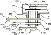
图2是本发明晶圆传输装置第一实心轴部分局部放大图。Fig. 2 is a partially enlarged view of the first solid axis of the wafer transfer device of the present invention.
图3是本发明晶圆传输装置第二实心轴部分局部放大图。FIG. 3 is a partially enlarged view of the second solid axis of the wafer transfer device of the present invention.
图4是本发明晶圆传输装置第三实心轴部分局部放大图。Fig. 4 is a partially enlarged view of the third solid axis of the wafer transfer device of the present invention.
图中:In the picture:
100-基座100-base
101-第一机械臂;102-第二机械臂;103-第三机械臂;101-the first mechanical arm; 102-the second mechanical arm; 103-the third mechanical arm;
201-第一电机;202-第二电机;203-第三电机;201-the first motor; 202-the second motor; 203-the third motor;
211-第一钢带;212-第二钢带;213-第三钢带;214-第四钢带;215-第五钢带;216-第六钢带;211-the first steel strip; 212-the second steel strip; 213-the third steel strip; 214-the fourth steel strip; 215-the fifth steel strip; 216-the sixth steel strip;
221-第一带轮;222-第二带轮;223-第三带轮;224-第四带轮;225-第五带轮;226-第六带轮;227-第七带轮;228-第八带轮;229-第九带轮;2210-第十带轮;2211-第十一带轮;2212-第十二带轮;221-the first pulley; 222-the second pulley; 223-the third pulley; 224-the fourth pulley; 225-the fifth pulley; 226-the sixth pulley; 227-the seventh pulley; 228 - the eighth pulley; 229 - the ninth pulley; 2210 - the tenth pulley; 2211 - the eleventh pulley; 2212 - the twelfth pulley;
231-第一实心轴;232-第二实心轴;233-第三实心轴;234-套筒轴;231-first solid shaft; 232-second solid shaft; 233-third solid shaft; 234-sleeve shaft;
901-第一轴线;902-第二轴线;903-第三轴线。901 - first axis; 902 - second axis; 903 - third axis.
具体实施方式 Detailed ways
下面结合附图对本发明实施方式作进一步详细描述。The embodiments of the present invention will be further described in detail below in conjunction with the accompanying drawings.
图1、图2、图3和图4是本发明晶圆传输装置的结构图,包括基座100、第一机械臂101、第二机械臂102、第三机械臂103,第一电机201、第二电机202、第三电机203、第一钢带211、第二钢带212、第三钢带213、第四钢带214、第五钢带215、第六钢带216、第一带轮221、第二带轮222、第三带轮223、第四带轮224、第五带轮225、第六带轮226、第七带轮227、第八带轮228、第九带轮229、第十带轮2210、第十一带轮2211、第十二带轮2212、第一实心轴231、第二实心轴232、第三实心轴233和套筒轴234。第一电机201、第二电机202和第三电机203固定在基座100上。Fig. 1, Fig. 2, Fig. 3 and Fig. 4 are the structural diagrams of the wafer transfer device of the present invention, including
第一实心轴231与套筒轴234同轴安装,相互之间可以转动;第一实心轴231、第二实心轴232与第三实心轴233轴线相互平行安装。The first
第一机械臂101与第二机械臂102分别通过轴承第二实心轴232连接,第二机械臂102与第三机械臂103分别通过轴承第三实心轴233连接。The first
第一带轮221固定在第一电机201的输出轴上,第三带轮223固定在第二电机202的输出轴上,第七带轮227固定在第三电机203的输出轴上;第四带轮224与第五带轮225分别固定在第一实心轴231的两端,第十带轮2210与第十一带轮2211分别固定在第二实心轴232的两端,第十二带轮2212固定在第三实心轴233上,第八带轮228与第九带轮229分别固定在套筒轴234的两端;第二带轮222固定在第一机械臂101上,第六带轮226固定在第二机械臂102上。The
通过第一钢带211连接第一带轮221和第二带轮222的运动,通过第二钢带212连接第三带轮223和第四带轮224的运动,通过第三钢带213连接第五带轮225和第六带轮226的运动,通过第四钢带214连接第七带轮227和第八带轮228的运动,通过第五钢带215连接第九带轮229和第十带轮2210的运动,通过第六钢带216连接第十一带轮2211和第十二带轮2212的运动。The movement of the
第一电机201、第二电机202和第三电机203固定在基座100上,分别控制第一机械臂101、第二机械臂102和第三机械臂103的运动。The
图2是本发明晶圆传输装置第一实心轴部分局部放大图,第一实心轴231与套筒轴234同轴安装;第一电机201通过第一带轮221、第一钢带211和第二带轮222将动力传递给第一机械臂101,带动第一机械臂101相对于第一实心轴231的旋转运动;第二电机202通过第三带轮223、第二钢带212和第四带轮224将动力传递给第一实心轴231,且动力通过第五带轮225输出;第三电机203通过第七带轮227、第四钢带214和第八带轮228将动力传递给套筒轴234,且动力由第九带轮229输出。2 is a partially enlarged view of the first solid shaft of the wafer transfer device of the present invention. The first
图3是本发明晶圆传输装置第二实心轴部分局部放大图,第一机械臂101与第二机械臂102分别通过轴承第二实心轴232连接;第五带轮225传递的第二电机202驱动力通过第三钢带213、第六带轮226传递至第二机械臂102,带动第二机械臂102相对于第二实心轴232的旋转运动;第九带轮229传递的第三电机203驱动力通过第五钢带215、第十带轮2210传递至第二实心轴232,且动力由第十一带轮2211输出。3 is a partially enlarged view of the second solid shaft of the wafer transfer device of the present invention. The first
图4是本发明晶圆传输装置第三实心轴部分局部放大图,第二机械臂102与第三机械臂103分别通过轴承与第三实心轴233连接;第十一带轮2212传递的第三电机203驱动力通过第六钢带216和第十二带轮2212传递至第三实心轴,带动第三机械臂103相对于第三实心轴103的旋转运动。4 is a partially enlarged view of the third solid shaft of the wafer transfer device of the present invention. The second
Claims (1)
Priority Applications (1)
| Application Number | Priority Date | Filing Date | Title |
|---|---|---|---|
| CN2012101920806A CN102709221A (en) | 2011-06-28 | 2012-06-11 | Planar three degree-of-freedom wafer transmitting device |
Applications Claiming Priority (3)
| Application Number | Priority Date | Filing Date | Title |
|---|---|---|---|
| CN201110177870.2 | 2011-06-28 | ||
| CN201110177870 | 2011-06-28 | ||
| CN2012101920806A CN102709221A (en) | 2011-06-28 | 2012-06-11 | Planar three degree-of-freedom wafer transmitting device |
Publications (1)
| Publication Number | Publication Date |
|---|---|
| CN102709221A true CN102709221A (en) | 2012-10-03 |
Family
ID=46901884
Family Applications (1)
| Application Number | Title | Priority Date | Filing Date |
|---|---|---|---|
| CN2012101920806A Pending CN102709221A (en) | 2011-06-28 | 2012-06-11 | Planar three degree-of-freedom wafer transmitting device |
Country Status (1)
| Country | Link |
|---|---|
| CN (1) | CN102709221A (en) |
Cited By (2)
| Publication number | Priority date | Publication date | Assignee | Title |
|---|---|---|---|---|
| WO2017069920A1 (en) * | 2015-10-23 | 2017-04-27 | Applied Materials, Inc | Robot assemblies, substrate processing apparatus, and methods for transporting substrates in electronic device manufacturing |
| CN115892990A (en) * | 2022-11-16 | 2023-04-04 | 海目星激光智能装备(江苏)有限公司 | Pole piece transfer device |
Citations (3)
| Publication number | Priority date | Publication date | Assignee | Title |
|---|---|---|---|---|
| US20020066330A1 (en) * | 2000-11-17 | 2002-06-06 | Hirotoshi Namba | Double arm substrate transport unit |
| US20060099063A1 (en) * | 2004-06-09 | 2006-05-11 | Pietrantonio Antonio F | Dual scara arm |
| US20100178147A1 (en) * | 2009-01-11 | 2010-07-15 | Applied Materials, Inc. | Robot systems, apparatus and methods for transporting substrates |
-
2012
- 2012-06-11 CN CN2012101920806A patent/CN102709221A/en active Pending
Patent Citations (3)
| Publication number | Priority date | Publication date | Assignee | Title |
|---|---|---|---|---|
| US20020066330A1 (en) * | 2000-11-17 | 2002-06-06 | Hirotoshi Namba | Double arm substrate transport unit |
| US20060099063A1 (en) * | 2004-06-09 | 2006-05-11 | Pietrantonio Antonio F | Dual scara arm |
| US20100178147A1 (en) * | 2009-01-11 | 2010-07-15 | Applied Materials, Inc. | Robot systems, apparatus and methods for transporting substrates |
Cited By (6)
| Publication number | Priority date | Publication date | Assignee | Title |
|---|---|---|---|---|
| WO2017069920A1 (en) * | 2015-10-23 | 2017-04-27 | Applied Materials, Inc | Robot assemblies, substrate processing apparatus, and methods for transporting substrates in electronic device manufacturing |
| US9799544B2 (en) | 2015-10-23 | 2017-10-24 | Applied Materials, Inc. | Robot assemblies, substrate processing apparatus, and methods for transporting substrates in electronic device manufacturing |
| CN108028215A (en) * | 2015-10-23 | 2018-05-11 | 应用材料公司 | Mechanical arm assembly, substrate board treatment and the method for transmitting substrate in electronic equipment manufacturing |
| TWI704038B (en) * | 2015-10-23 | 2020-09-11 | 美商應用材料股份有限公司 | Robot assemblies, substrate processing apparatus, and methods for transporting substrates in electronic device manufacturing |
| CN108028215B (en) * | 2015-10-23 | 2022-07-29 | 应用材料公司 | Robot assembly, substrate processing apparatus, and method for transferring substrate in electronic device manufacturing |
| CN115892990A (en) * | 2022-11-16 | 2023-04-04 | 海目星激光智能装备(江苏)有限公司 | Pole piece transfer device |
Similar Documents
| Publication | Publication Date | Title |
|---|---|---|
| US8234949B2 (en) | Power transmission mechanism and robot arm using the same | |
| CN201808063U (en) | Six-degrees-of-freedom parallel robot device | |
| US8511198B2 (en) | Robot arm system | |
| US8511197B2 (en) | Robot arm assembly | |
| CN102615652B (en) | Two-degree-of-freedom robot joint based on double-electromagnetic clutch | |
| CN109760029B (en) | Flat single-arm robot based on synchronous pulley transmission | |
| CN202049666U (en) | Teaching instrument of arm transmission structure of robot | |
| CN118876108B (en) | A rope-driven three-degree-of-freedom hybrid spherical wrist joint | |
| CN104626113A (en) | Connecting rod and synchronous belt combined transmission four-degree-of-freedom robot | |
| CN103481283A (en) | Three-axis five-bar parallel manipulator | |
| CN102554914A (en) | Novel three-degrees-of-freedom under-actuated mechanism | |
| CN105041993A (en) | Reduction gear for SCARA industrial robot | |
| CN107717959A (en) | A kind of SCARA high-speed parallel manipulators of partly decoupled | |
| CN103802090A (en) | Dual-arm carrying manipulator | |
| CN103264399A (en) | Robot waist-arm integrated synchronous double-drive mechanism and control method thereof | |
| CN102709221A (en) | Planar three degree-of-freedom wafer transmitting device | |
| CN110561489B (en) | A three-degree-of-freedom parallel drive joint | |
| CN104690713B (en) | A kind of four-degree-of-freedom sorting machine people in parallel | |
| CN204748650U (en) | Robot joint structure | |
| CN106863264B (en) | Four-degree-of-freedom parallel robot movable platform | |
| CN108167394B (en) | A Rotating Base and Cylindrical Coordinate System Robot | |
| CN202622818U (en) | Two-degree-of-freedom robot joint device based on double-electromagnetic clutch | |
| CN204784506U (en) | Decelerator for SCARA industrial robot | |
| CN102615642B (en) | Parallel manipulator capable of realizing five-coordinate machining capacity | |
| CN218953949U (en) | Screw rod assembly and robot |
Legal Events
| Date | Code | Title | Description |
|---|---|---|---|
| C06 | Publication | ||
| PB01 | Publication | ||
| C10 | Entry into substantive examination | ||
| SE01 | Entry into force of request for substantive examination | ||
| C02 | Deemed withdrawal of patent application after publication (patent law 2001) | ||
| WD01 | Invention patent application deemed withdrawn after publication |
Application publication date: 20121003 |