CN102777023A - Construction platform transmission mechanism - Google Patents

Construction platform transmission mechanism Download PDF

Info

Publication number
CN102777023A
CN102777023A CN2012102572491A CN201210257249A CN102777023A CN 102777023 A CN102777023 A CN 102777023A CN 2012102572491 A CN2012102572491 A CN 2012102572491A CN 201210257249 A CN201210257249 A CN 201210257249A CN 102777023 A CN102777023 A CN 102777023A
Authority
CN
China
Prior art keywords
gear
winch
main beam
input shaft
rotating shaft
Prior art date
Legal status (The legal status is an assumption and is not a legal conclusion. Google has not performed a legal analysis and makes no representation as to the accuracy of the status listed.)
Granted
Application number
CN2012102572491A
Other languages
Chinese (zh)
Other versions
CN102777023B (en
Inventor
孙涛
陈晓东
Current Assignee (The listed assignees may be inaccurate. Google has not performed a legal analysis and makes no representation or warranty as to the accuracy of the list.)
China State Construction Engineering Corp Ltd CSCEC
China Construction Baili Engineering Technology Development Co Ltd
Original Assignee
China State Construction Engineering Corp Ltd CSCEC
China Construction Baili Engineering Technology Development Co Ltd
Priority date (The priority date is an assumption and is not a legal conclusion. Google has not performed a legal analysis and makes no representation as to the accuracy of the date listed.)
Filing date
Publication date
Application filed by China State Construction Engineering Corp Ltd CSCEC, China Construction Baili Engineering Technology Development Co Ltd filed Critical China State Construction Engineering Corp Ltd CSCEC
Priority to CN201210257249.1A priority Critical patent/CN102777023B/en
Publication of CN102777023A publication Critical patent/CN102777023A/en
Application granted granted Critical
Publication of CN102777023B publication Critical patent/CN102777023B/en
Expired - Fee Related legal-status Critical Current
Anticipated expiration legal-status Critical

Links

Images

Classifications

    • EFIXED CONSTRUCTIONS
    • E04BUILDING
    • E04GSCAFFOLDING; FORMS; SHUTTERING; BUILDING IMPLEMENTS OR AIDS, OR THEIR USE; HANDLING BUILDING MATERIALS ON THE SITE; REPAIRING, BREAKING-UP OR OTHER WORK ON EXISTING BUILDINGS
    • E04G21/00Preparing, conveying, or working-up building materials or building elements in situ; Other devices or measures for constructional work
    • E04G21/14Conveying or assembling building elements
    • E04G21/16Tools or apparatus
    • E04G21/166Landings, receiving platforms

Landscapes

  • Engineering & Computer Science (AREA)
  • Architecture (AREA)
  • Mechanical Engineering (AREA)
  • Civil Engineering (AREA)
  • Structural Engineering (AREA)
  • Types And Forms Of Lifts (AREA)

Abstract

一种建筑施工平台传动机构,包括固定连接在固定主梁的主梁翼缘上的绞盘支撑架、固定连接在绞盘支撑架上的绞盘、固定连接在固定主梁的主梁腹板上的齿轮组、以及固定连接在移动平台的平台主梁上的齿条,所述绞盘包括螺栓连接在绞盘支撑架上的绞盘壳体、铰接连接绞盘壳体上的输入转轴一、以及同轴转动连接在输入转轴一上的主动链轮,所述齿轮组包括固定连接在固定主梁的主梁腹板上的齿轮支撑板、穿在齿轮支撑板和固定主梁的主梁腹板上的齿轮转轴、以及同轴转动连接在齿轮转轴上的从动链轮和同步齿轮。本机构将移动平台的前后移动方式由人力推动改为通过人工摇动减速绞盘,在保护了施工人员安全的前提下,最大限度的降低了施工人员的劳动强度。

Figure 201210257249

A construction platform transmission mechanism, comprising a winch support frame fixedly connected to the main beam flange of the fixed main beam, a winch fixedly connected to the winch support frame, a gear set fixedly connected to the main beam web plate of the fixed main beam, And the rack that is fixedly connected on the platform girder of the mobile platform, the winch includes a winch shell bolted on the winch support frame, an input shaft one hingedly connected to the winch shell, and a coaxial rotation connected to the input shaft One drive sprocket, the gear set includes a gear support plate fixedly connected to the main beam web of the fixed main beam, a gear shaft passing through the gear support plate and the main beam web of the fixed main beam, and the same The shaft rotates the driven sprocket and synchronous gear connected to the gear shaft. This mechanism changes the forward and backward movement of the mobile platform from human propulsion to manually shaking the deceleration winch, which minimizes the labor intensity of the construction personnel on the premise of protecting the safety of the construction personnel.

Figure 201210257249

Description

The construction platform transmission mechanism
Technical field
The present invention relates to a kind of platform travel mechanism that is installed on the portable construction platform.
Background technology
In today of the continuous development of construction implement, construction platform mainly demonstrates two kinds of design directions, and a kind of is conventional fixed formula operation platform, and another kind is portable operation platform.Existing portable operation platform mainly relies on pleading of 4~6 constructor's manpowers; Could the mobile platform in the portable operation platform (or being carrying platform) be moved into or shift out; This mode has not only strengthened constructor's labour intensity, has also increased constructor's operational danger greatly.
Summary of the invention
The purpose of this invention is to provide a kind of construction platform transmission mechanism, solve the technical problem that the mobile platform in traditional portable operation platform can only lean on manpower to move into or shift out.
For realizing above-mentioned purpose; The present invention adopts following technical scheme: a kind of construction platform transmission mechanism; Be connected in the construction platform mobile platform and fixedly between the girder, it is characterized in that: comprise capstan winch bracing frame on the girder edge of a wing that is fixedly connected on fixing girder, be fixedly connected on capstan winch on the capstan winch bracing frame, be fixedly connected on the gear train on the girder web of fixing girder and be fixedly connected on the tooth bar on the platform girder of mobile platform.
Said capstan winch comprises that bolt is connected the capstan winch housing on the capstan winch bracing frame, input rotating shaft one and the coaxial rotation that is connected on the capstan winch housing is connected the drive sprocket in the input rotating shaft one; Said gear train comprises gear gripper shoe on the girder web that is fixedly connected on fixing girder, be through the gear gripper shoe and fixedly rotary gear shaft and the coaxial rotation on the girder web of girder be connected driven sprocket and synchromesh gear on the rotary gear shaft; Said drive sprocket is connected with driven sprocket through chain, said synchromesh gear and tooth bar engagement.
Be connected with capstan cover on the said capstan winch housing.
Said capstan winch bracing frame is provided with vertical slotted hole, and said capstan winch housing is connected on the capstan winch bracing frame through bolt and vertical slotted hole.
The head of said input rotating shaft one can be provided with the connector that removably connects with handle.
Can also be hingedly connected with input rotating shaft two on the said capstan winch housing, coaxial rotation is connected with gear two in the input rotating shaft two, and coaxial rotation is connected with gear one and gear one is meshed with gear two in the said input rotating shaft one.The head of said input rotating shaft one all can be provided with the connector that removably connects with handle with the head of input rotating shaft two.
Can also be hingedly connected with input rotating shaft three on the said capstan winch housing, coaxial rotation is connected with gear three in the input rotating shaft three, and coaxial rotation is connected with gear four and gear four is meshed with gear three in the said input rotating shaft two.The head of the head of the head of said input rotating shaft one, input rotating shaft two and input rotating shaft three all can be provided with the connector that removably connects with handle.
Compared with prior art the present invention has following characteristics and beneficial effect: the present invention is a kind of transmission mechanism that is applied in the portable construction platform; Especially be fit to be applied on the movably overhanging type operation platform in the high-building construction; Can make mobile platform realize independently moving forward and backward (, mobile platform is moved forward and backward along fixing girder) through the present invention.
The present invention is a kind of optimization that is directed to the kind of drive of portable construction platform; It can change the mode that moves forward and backward of mobile platform through manual work into by people's force urges and shake the deceleration capstan winch; Under the prerequisite of having protected constructor's safety, reduced constructor's labour intensity to greatest extent.
Description of drawings
Below in conjunction with accompanying drawing the present invention is done further detailed explanation.
Fig. 1 is an installation site of the present invention sketch map.
Fig. 2 looks sketch map of the present invention sideways from fixing girder outer.
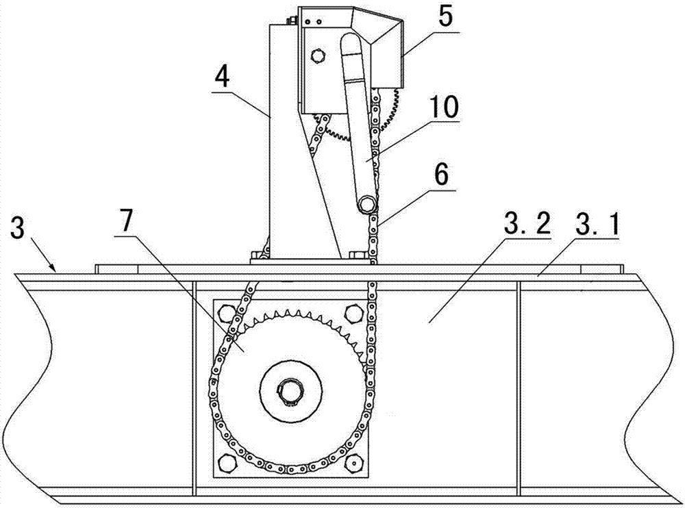
Fig. 3 is from fixedly looking sketch map of the present invention sideways in the girder.
Fig. 4 is that master of the present invention looks sketch map.
Fig. 5 is that capstan winch is looked sketch map with the master that the capstan winch bracing frame is connected.
Fig. 6 is that sketch map is looked on the left side of Fig. 5.
Fig. 7 is that the master of capstan winch looks sketch map.
Fig. 8 is that sketch map is looked on the right side of Fig. 7.
Fig. 9 is the schematic top plan view of Fig. 8.
Figure 10 is that the master of gear train looks sketch map.
Figure 11 is that sketch map is looked on the right side of Figure 10.
Accompanying drawing mark: 1-mobile platform; 1.1-platform girder; 2-construction platform transmission mechanism; 3-is girder fixedly; 3.1-the girder edge of a wing; 3.2-girder web; 4-capstan winch bracing frame; The 5-capstan winch; The 6-chain; The 7-gear train; The 8-tooth bar; The 9-capstan cover; The 10-handle; 11-capstan winch housing; 12-gear one; 13-gear two; 14-gear three; 15-gear four; The 16-connector; The 17-steady pin; The 18-drive sprocket; 19-imports rotating shaft three; 20-imports rotating shaft two; 21-imports rotating shaft one; The 22-driven sprocket; 23-gear gripper shoe; The 24-synchromesh gear; The 25-key; The 26-snap ring; The 27-rotary gear shaft; The 28-axle sleeve; The vertical slotted hole of 29-; The 30-bolt.
The specific embodiment
Embodiment is referring to shown in Fig. 1-4; This construction platform transmission mechanism 2; Be connected in the construction platform mobile platform 1 and fixedly between the girder 3, comprise capstan winch bracing frame 4 on the girder edge of a wing 3.1 that is fixedly connected on fixing girder 3, be fixedly connected on capstan winch 5 on the capstan winch bracing frame 4, be fixedly connected on the gear train 7 on the girder web 3.2 of fixing girder 3 and be fixedly connected on the tooth bar 8 on the platform girder 1.1 of mobile platform 1.
Referring to Fig. 2-4, Fig. 7-11; Said capstan winch 5 comprises that bolt is connected the capstan winch housing 11 on the capstan winch bracing frame 4, input rotating shaft 1 and the coaxial rotation that is connected on the capstan winch housing 11 is connected the drive sprocket 18 in the input rotating shaft 1; Said gear train 7 comprises gear gripper shoe 23 on the girder web that is fixedly connected on fixing girder 3 (being connected fixing with the fixing girder web of girder 3 through M20 bolt 11), be through the gear gripper shoe and fixedly rotary gear shaft 27 (rotary gear shaft 27 is through on gear gripper shoe and the girder web through axle sleeve) and the coaxial rotation on the girder web of girder be connected driven sprocket 22 and synchromesh gear 24 on the rotary gear shaft 27; Said drive sprocket 18 is connected (being that chain 6 is installed on drive sprocket 18 and the driven sprocket 22) through chain 6 with driven sprocket 22, said synchromesh gear 24 and tooth bar 8 engagements.Referring to Fig. 5, in the present embodiment, be connected with capstan cover 9 on the capstan winch housing 11.
Referring to Fig. 7-9; In order to reduce constructor's labour intensity; In the present embodiment; Also be connected with input rotating shaft 2 20 on the capstan winch housing 11, coaxial rotation is connected with gear 2 13 in the input rotating shaft 2 20, and coaxial rotation is connected with gear 1 and gear 1 is meshed with gear 2 13 in the said input rotating shaft 1.Also be connected with input rotating shaft 3 19 on the capstan winch housing 11, coaxial rotation is connected with gear 3 14 in the input rotating shaft 3 19, and coaxial rotation is connected with gear 4 15 and gear 4 15 is meshed with gear 3 14 in the said input rotating shaft 2 20.That is to say that present embodiment has adopted the design of 3 parallel axes deceleration capstan winches, through gears engaged, by capstan winch 3 kinds of speed reducing ratio (this structure makes capstan winch that 3 speed reducing ratio arranged) is provided, and is 3 grades of deceleration capstan winches.
The characteristics of present embodiment are through artificial hand capstan, drive sprocket wheel, chain and gear, tooth bar transmission.Referring to Fig. 5-9; In the present embodiment; The mode of moving forward and backward of mobile platform 1 is to shake capstan winch through manual work to realize; Promptly import the head of rotating shaft 1, the head of input rotating shaft 2 20 and the head of input rotating shaft 3 19 and be equipped with the connector 16 that removably connects with handle 10, handle 10 removably connects through connector 16 and input rotating shaft 1, input rotating shaft 2 20 or input rotating shaft 3 19.
When handle 10 is installed in input one 21 last times of rotating shaft, the input and output speed reducing ratio of capstan winch is 1: 1, promptly imports rotating shaft one: drive sprocket=1: 1.When handle 10 is installed in input 2 20 last times of rotating shaft, the input and output speed reducing ratio of capstan winch is 5: 1, promptly imports rotating shaft two: drive sprocket=5: 1.When handle 10 is installed in input 3 19 last times of rotating shaft, the input and output speed reducing ratio of capstan winch is 15: 1, promptly imports rotating shaft three: drive sprocket=15: 1.The rotating ratio of the input rotating shaft in the capstan winch is input rotating shaft one: input rotating shaft two: input rotating shaft three=1: 5: 15.
In other embodiments, according to condition of construction and peopleware, capstan winch can also design multiple different rotating speed ratio.
In other embodiments, also can drive input rotating shaft 1, input rotating shaft 2 20 or input rotating shaft 3 19 with motor rotates.
In the present embodiment, gear one, gear two, gear three and gear four all adopt spur gear engagement design.Gear 1, gear 2 13, gear 3 14 and gear 4 15 all are to fix through steady pin 17 (spring pin) and input rotating shaft; Specifically; Be exactly all to be welded with axle sleeve on gear 1, gear 2 13, gear 3 14 and the gear 4 15, axle sleeve is fixed in the input rotating shaft through the spring pin more then.The axle sleeve of welding is excessive axle sleeve on the said gear 1, and gear 1 keeps axial distance through excessive axle sleeve and drive sprocket 18.Said drive sprocket 18 and input rotating shaft one 21 welding.
Said synchromesh gear 24 adopts welding fixing with rotary gear shaft 27, has guaranteed the one fastness of synchromesh gear and rotary gear shaft.Said driven sprocket 22 adopts keys 25 and snap ring 26 to be connected with rotary gear shaft 27, and key 25 can make driven sprocket and rotary gear shaft 27 synchronous, and snap ring 26 can be realized the axial restraint of driven sprocket.
Referring to Fig. 5, Fig. 6, said capstan winch bracing frame adopts the stand type support structure, and upper and lower side respectively has a mounting flange and vertical each other, and wherein the mounting flange of upper end is installed with capstan winch housing 11, and the bolt of the mounting flange employing M20 of lower end is connected with fixing girder.In the present embodiment, the mounting flange of capstan winch bracing frame 4 upper ends is provided with three vertical slotted holes 29 (being waist-shaped hole again), on the mounting flange of the upper end that bolt 30 and three vertical slotted holes 29 of said capstan winch housing 11 through 3 cover M10 is connected capstan winch bracing frame 4.Vertical slotted hole on the capstan winch bracing frame 4 can be regulated the elasticity of chain.
Said capstan winch housing 11 adopts the design of U shaped shell; U shaped shell front end is provided with support rail, is furnished with 3 axis holes on the capstan winch housing, and the circular hole design is adopted at capstan winch housing back; Conveniently be connected with the capstan winch bracing frame; The sidewall upper of capstan winch housing is provided with 2 groups of symmetrical screwed holes, as fixedly capstan cover (protective cover) use.Be embedded with in 3 axis holes on the capstan winch housing and import the termination axle sleeve that rotating shaft cooperates, the termination axle sleeve can be avoided the wearing and tearing of capstan winch housing, increases the Area of bearing of input rotating shaft simultaneously.
In the present embodiment; For guaranteeing the operating attitude of constructor when manoeuvring platform moves; Utilize the capstan winch bracing frame; The design height of the input rotating shaft in the capstan winch (promptly importing rotating shaft 1, input rotating shaft 2 20 or input rotating shaft 3 19) is decided to be 830mm, guarantees that the constructor can rationally utilize the strength of self.
The operating principle of construction platform transmission mechanism 2 is: the present invention can move into or shift out building with the mobile platform of the nearly 3t of deadweight; It adopts the engaged transmission of gear, tooth bar; By the synchromesh gear on the girder web that is installed on fixing girder 3 as the power output; Act on the tooth bar on the platform girder that is fixed on mobile platform 1; The synchromesh gear 24 that is installed on the fixing girder 3 is meshing with each other with the tooth bar 8 that is installed on the mobile platform 1, drives mobile platform 1 and moves forward and backward, and realizes the flexible effect of mobile platform.
The concrete power transmission mode of present embodiment is that the constructor can select any handle installation 10 in three input rotating shafts on the capstan winch 5, through turning handle 10; The gear that drives on the capstan winch 5 rotates, and the mutual engagement of gear realizes the deceleration effect, and the drive sprocket 18 that drives in the input rotating shaft 1 rotates; Drive sprocket 18 makes transmission of power to gear train through the transmission of chain 6, and the driven sprocket 22 in the driven gear group rotates; Gear train adopts sprocket wheel and the synchronous design of gear; Rotate so also driven synchromesh gear 24, and because synchromesh gear 24 and tooth bar engagement, so can make tooth bar do displacement with respect to gear position.

Claims (8)

1.一种建筑施工平台传动机构,连接在建筑施工平台中的移动平台(1)与固定主梁(3)之间,其特征在于:包括固定连接在固定主梁(3)的主梁翼缘上的绞盘支撑架(4)、固定连接在绞盘支撑架(4)上的绞盘(5)、固定连接在固定主梁(3)的主梁腹板上的齿轮组(7)、以及固定连接在移动平台(1)的平台主梁上的齿条(8); 1. A transmission mechanism for a building construction platform, which is connected between the mobile platform (1) and the fixed main beam (3) in the building construction platform, and is characterized in that it includes a fixed connection on the main beam flange of the fixed main beam (3). The winch support frame (4), the winch (5) fixedly connected on the winch support frame (4), the gear set (7) fixedly connected to the main beam web plate of the fixed main beam (3), and the fixed connection on The rack (8) on the platform girder of the mobile platform (1); 所述绞盘(5)包括螺栓连接在绞盘支撑架(4)上的绞盘壳体(11)、连接在绞盘壳体(11)上的输入转轴一(21)、以及同轴转动连接在输入转轴一(21)上的主动链轮(18),所述齿轮组(7)包括固定连接在固定主梁(3)的主梁腹板上的齿轮支撑板(23)、穿在齿轮支撑板和固定主梁的主梁腹板上的齿轮转轴(27)、以及同轴转动连接在齿轮转轴(27)上的从动链轮(22)和同步齿轮(24),所述主动链轮(18)通过链条(6)与从动链轮(22)连接,所述同步齿轮(24)与齿条(8)啮合。 The winch (5) includes a winch housing (11) connected by bolts to the winch support frame (4), an input shaft one (21) connected to the winch housing (11), and a coaxially rotating shaft connected to the input shaft One (21) on the drive sprocket (18), the gear set (7) includes a gear support plate (23) fixedly connected to the main beam web of the fixed main beam (3), worn on the gear support plate and The gear shaft (27) on the main beam web plate of the fixed main beam, and the driven sprocket (22) and the synchronous gear (24) connected to the gear shaft (27) for coaxial rotation, the driving sprocket (18 ) is connected with the driven sprocket (22) through the chain (6), and the synchronous gear (24) is meshed with the rack (8). 2.根据权利要求1所述的建筑施工平台传动机构,其特征在于:所述绞盘壳体(11)上连接有绞盘罩(9)。 2. The construction platform transmission mechanism according to claim 1, characterized in that: the winch housing (11) is connected with a winch cover (9). 3.根据权利要求1所述的建筑施工平台传动机构,其特征在于:所述绞盘支撑架(4)上设有竖向长孔(29),所述绞盘壳体(11)通过螺栓(30)和竖向长孔(29)连接在绞盘支撑架(4)上。 3. The construction platform transmission mechanism according to claim 1, characterized in that: the winch support frame (4) is provided with a vertical long hole (29), and the winch housing (11) is passed through a bolt (30 ) and the vertical long hole (29) are connected on the winch support frame (4). 4.根据权利要求1所述的建筑施工平台传动机构,其特征在于:所述输入转轴一(21)的头部设有与手柄(10)可拆卸连接的连接头(16)。 4. The construction platform transmission mechanism according to claim 1, characterized in that: the head of the first input shaft (21) is provided with a connector (16) detachably connected to the handle (10). 5.根据权利要求1所述的建筑施工平台传动机构,其特征在于:所述绞盘壳体(11)上还连接有输入转轴二(20),输入转轴二(20)上同轴转动连接有齿轮二(13),所述输入转轴一(21)上同轴转动连接有齿轮一(12)并且齿轮一(12)与齿轮二(13)相啮合。 5. The construction platform transmission mechanism according to claim 1, characterized in that: the winch housing (11) is also connected with the second input shaft (20), and the second input shaft (20) is coaxially connected with The second gear (13), the first input shaft (21) is coaxially connected with the first gear (12) and the first gear (12) is meshed with the second gear (13). 6.根据权利要求5所述的建筑施工平台传动机构,其特征在于:所述输入转轴一(21)的头部和输入转轴二(20)的头部均设有与手柄(10)可拆卸连接的连接头(16)。 6. The construction platform transmission mechanism according to claim 5, characterized in that: the head of the first input shaft (21) and the head of the second input shaft (20) are equipped with handles (10) detachable connected connector (16). 7.根据权利要求5所述的建筑施工平台传动机构,其特征在于:所述绞盘壳体(11)上还连接有输入转轴三(19),输入转轴三(19)上同轴转动连接有齿轮三(14),所述输入转轴二(20)上同轴转动连接有齿轮四(15)并且齿轮四(15)与齿轮三(14)相啮合。 7. The construction platform transmission mechanism according to claim 5, characterized in that: the winch housing (11) is also connected with an input rotating shaft three (19), and the input rotating shaft three (19) is coaxially connected with a The third gear (14), the second input shaft (20) is coaxially connected with the fourth gear (15) and the fourth gear (15) is meshed with the third gear (14). 8.根据权利要求7所述的建筑施工平台传动机构,其特征在于:所述输入转轴一(21)的头部、输入转轴二(20)的头部和输入转轴三(19)的头部均设有与手柄(10)可拆卸连接的连接头(16)。 8. The construction platform transmission mechanism according to claim 7, characterized in that: the head of the first input shaft (21), the head of the second input shaft (20) and the head of the third input shaft (19) Both are provided with a connector (16) detachably connected to the handle (10).
CN201210257249.1A 2012-07-24 2012-07-24 Construction platform transmission mechanism Expired - Fee Related CN102777023B (en)

Priority Applications (1)

Application Number Priority Date Filing Date Title
CN201210257249.1A CN102777023B (en) 2012-07-24 2012-07-24 Construction platform transmission mechanism

Applications Claiming Priority (1)

Application Number Priority Date Filing Date Title
CN201210257249.1A CN102777023B (en) 2012-07-24 2012-07-24 Construction platform transmission mechanism

Publications (2)

Publication Number Publication Date
CN102777023A true CN102777023A (en) 2012-11-14
CN102777023B CN102777023B (en) 2014-07-02

Family

ID=47122117

Family Applications (1)

Application Number Title Priority Date Filing Date
CN201210257249.1A Expired - Fee Related CN102777023B (en) 2012-07-24 2012-07-24 Construction platform transmission mechanism

Country Status (1)

Country Link
CN (1) CN102777023B (en)

Families Citing this family (1)

* Cited by examiner, † Cited by third party
Publication number Priority date Publication date Assignee Title
CN111491885A (en) * 2017-11-03 2020-08-04 联升Ip私人有限公司 Lifting platform system for multi-storey building construction

Citations (8)

* Cited by examiner, † Cited by third party
Publication number Priority date Publication date Assignee Title
JPH07291558A (en) * 1994-04-22 1995-11-07 Yoshitada Etsuhara Elevator for work
CN2529945Y (en) * 2002-04-02 2003-01-08 史丹福(上海)工程机械有限公司 Mobile scaffold
CZ296410B6 (en) * 1997-05-16 2006-03-15 Construction platform
CN2828210Y (en) * 2005-10-13 2006-10-18 张含廉 Movable lifting working platform
CN201047159Y (en) * 2007-06-14 2008-04-16 汤文水 Hand-operated type hoister
CA2602688A1 (en) * 2006-10-17 2008-04-17 Jlg Industries, Inc. Lever-actuated retractable wheel and movable platform using same
CN101205761A (en) * 2006-12-21 2008-06-25 西北工业大学 Lifting device for aerial work platform
CN201411898Y (en) * 2009-04-02 2010-02-24 湖南省第五工程有限公司 Sliding scaffold for high-altitude installation of steel net network frame structure

Patent Citations (8)

* Cited by examiner, † Cited by third party
Publication number Priority date Publication date Assignee Title
JPH07291558A (en) * 1994-04-22 1995-11-07 Yoshitada Etsuhara Elevator for work
CZ296410B6 (en) * 1997-05-16 2006-03-15 Construction platform
CN2529945Y (en) * 2002-04-02 2003-01-08 史丹福(上海)工程机械有限公司 Mobile scaffold
CN2828210Y (en) * 2005-10-13 2006-10-18 张含廉 Movable lifting working platform
CA2602688A1 (en) * 2006-10-17 2008-04-17 Jlg Industries, Inc. Lever-actuated retractable wheel and movable platform using same
CN101205761A (en) * 2006-12-21 2008-06-25 西北工业大学 Lifting device for aerial work platform
CN201047159Y (en) * 2007-06-14 2008-04-16 汤文水 Hand-operated type hoister
CN201411898Y (en) * 2009-04-02 2010-02-24 湖南省第五工程有限公司 Sliding scaffold for high-altitude installation of steel net network frame structure

Also Published As

Publication number Publication date
CN102777023B (en) 2014-07-02

Similar Documents

Publication Publication Date Title
CN201186742Y (en) surface garbage collection boat
CN106592402B (en) A kind of road cutting machine device people and its construction method
CA2788087A1 (en) Independently powered trolleys
CN104608841B (en) Wire tractor
CN102777023A (en) Construction platform transmission mechanism
CN202481102U (en) Electric ship pipe tunnel trolley
CN204847963U (en) Portable driver's cabin of hoist
CN117361417A (en) Portable manned monorail crane
CN209568974U (en) Multifunctional drilling machine for tunnel
CN202578505U (en) Novel transmission device for truck-mounted well drilling and workover rig
CN101509365B (en) Cluster well load mutually-balancing energy-conserving oil pumping system
CN101704475A (en) Novel crane
CN203832607U (en) Wire tractor
CN204878555U (en) Plough machine a little
CN202766979U (en) Walking-pedrail bridge girder erection machine landing leg walking mechanism
CN201787021U (en) Belt-gear driven negation gate control device of micro-farming machine
CN201377310Y (en) Cluster well load counterbalance energy-saving pumping system
CN201771435U (en) Portable ground anchor machine
CN2599846Y (en) Cable tractor
CN202577125U (en) Convenient-to-move pavement joint cutting machine
CN202441255U (en) Ultra-low-height hydraulic power head type rotary drilling machine
CN202560125U (en) Well drilling mouth elevator transporting device
CN202667726U (en) Bench drill overall mobile platform
CN2767028Y (en) Semi-open type orbit rotating disc
CN200999612Y (en) Split combination type kerving machine

Legal Events

Date Code Title Description
C06 Publication
PB01 Publication
C10 Entry into substantive examination
SE01 Entry into force of request for substantive examination
C14 Grant of patent or utility model
GR01 Patent grant
CF01 Termination of patent right due to non-payment of annual fee

Granted publication date: 20140702

Termination date: 20200724