CN1045251A - Folding crane with crane arm of three hinged parts - Google Patents
Folding crane with crane arm of three hinged parts Download PDFInfo
- Publication number
- CN1045251A CN1045251A CN 90101023 CN90101023A CN1045251A CN 1045251 A CN1045251 A CN 1045251A CN 90101023 CN90101023 CN 90101023 CN 90101023 A CN90101023 A CN 90101023A CN 1045251 A CN1045251 A CN 1045251A
- Authority
- CN
- China
- Prior art keywords
- crane arm
- section
- crane
- pulley
- folding
- Prior art date
- Legal status (The legal status is an assumption and is not a legal conclusion. Google has not performed a legal analysis and makes no representation as to the accuracy of the status listed.)
- Granted
Links
- 238000004804 winding Methods 0.000 claims description 13
- 238000009434 installation Methods 0.000 claims description 7
- 238000000034 method Methods 0.000 claims description 6
- 230000008569 process Effects 0.000 claims description 4
- 230000015556 catabolic process Effects 0.000 claims description 3
- 230000008093 supporting effect Effects 0.000 abstract description 3
- 239000003351 stiffener Substances 0.000 description 27
- 230000000694 effects Effects 0.000 description 7
- 230000000712 assembly Effects 0.000 description 4
- 238000000429 assembly Methods 0.000 description 4
- 230000007480 spreading Effects 0.000 description 3
- 230000009471 action Effects 0.000 description 1
- 230000015572 biosynthetic process Effects 0.000 description 1
- 230000000903 blocking effect Effects 0.000 description 1
- 230000000295 complement effect Effects 0.000 description 1
- 230000008602 contraction Effects 0.000 description 1
- 239000004744 fabric Substances 0.000 description 1
- 230000002349 favourable effect Effects 0.000 description 1
- 230000007246 mechanism Effects 0.000 description 1
- 230000004048 modification Effects 0.000 description 1
- 238000012986 modification Methods 0.000 description 1
- 230000001737 promoting effect Effects 0.000 description 1
- 238000007634 remodeling Methods 0.000 description 1
- 230000000630 rising effect Effects 0.000 description 1
- 230000007306 turnover Effects 0.000 description 1
- 238000005303 weighing Methods 0.000 description 1
Images


Landscapes
- Jib Cranes (AREA)
Abstract
A kind of hoisting crane that has by three sections distribute type crane arms of forming, the motor-driven cable wire 45 that a crane arm is folding and launch is housed, this cable wire is by bracket component 16,26 connect second section of crane arm and end section, this cable wire is fixed on and is placed in after poppet 16 tops on the section at the bottom of the crane arm, and between the top 21 of the top 34 of the front frame 26 on second section of the crane arm of being placed in and after poppet 16, constitute an assembly pulley 60, pass through some pulleys 47 of symmetric arrangement successively, 49,50,53,55,56,57, then by pulley assembly 58 by the supporting of after poppet top, 59, be rolled onto at last that to be positioned at the bottom of the crane arm crane arm on the section rear end folding and launch on capstan winch 44 reels.
Description
The present invention relates to a kind of folding hoisting crane, the hoisting crane of retractable supports post is particularly arranged, it is equipped with one to be hinged on and to support capital end And and have the crane arm of distributional effects in working order down, but the dolly of a distribute loads promptly is housed.Crane arm constitutes by three sections that are hinged.In the known manner, hoisting crane has the folding and expanding unit of a crane arm, this device with after pin down rope manipulation (mainly being lifting assembly pulley) and by means of a crane arm add cable wire and combine, the latter is connected with tracker action independently, act directly on the crane arm, thus the influence that makes crane arm not be subjected to pillar stiffener to stretch out state, with the residing environment of hoisting crane, fold or launch, make each section of crane arm take various relative positions.
The known hoisting crane that a kind of the above-mentioned type is arranged, its power operated crane arm fold and launch cable wire and form an assembly pulley.When hoisting crane was in running order, this cable wire just became the connection tie-rod on front and back support top.This arrangement makes an only device have two kinds of functions, promptly can be used as the connection tie-rod when work in order to folding and expansion crane arm when attaching/detaching,
Its main shortcoming is to make two kinds of functions all quite reasonable.For example, determine if the thickness of cable wire connects the function of tie-rod during by work that the folding and function launched, size is just too big certainly during concerning attaching/detaching, it is folding and launch the pulley and the capstan winch of assembly pulley therefore to be used for crane arm, and its size is also just excessive.
In addition, known hoisting crane above-mentioned, break-down crane just can not add the crane arm lengthening section simply on the ground and come the spreading crane arm.
The objective of the invention is to solve the problem of above-mentioned existence, its method is that the another weighing arm is set is folding and launch assembly pulley, by the support of one group of remodeling, second section of crane arm and end section is coupled together.In addition, this crane arm folding and expanding unit folding and that launch the 3rd section of assembly pulley and crane arm combines, can not pull down hoisting crane, just to adding the crane arm lengthening section at the 3rd section top japanning on the ground simply by the crane arm of three hinged parts, thus the lengthening crane arm.
For this reason, the present invention has the folding crane of the crane arm of three hinged parts, it is folding and launch cable wire and be fixed on and be placed at the bottom of the crane arm that And is continuing up to from installation the process of mode of operation on the after poppet top on the section to it is characterized by power operated crane arm, forms an assembly pulley between front frame top on second section of the crane arm and the after poppet top in the following manner being placed in: first pulley that has horizontal shaft earlier by lateral-supporting on the front frame top; Second pulley that on cantilever tip, has horizontal shaft again by lateral-supporting, this pulley basically with last pulley to directly; By being bearing in the 3rd pulley on the after poppet, this pulley has the axle perpendicular to above-mentioned horizontal shaft, is placed in the plane of after poppet, is contained in after poppet top and after poppet on the axis of symmetry of after poppet between the hinge-point on the section at the bottom of the crane arm again; Turn back to lateral-supporting on the 4th pulley that is provided with on the after poppet top and with second pulley coaxle by the route of symmetry again, the 5th pulley that on the front frame top and with first pulley coaxle, is provided with by lateral-supporting again, at last by an assembly that constitutes by two pulleys at least, these two pulleys are supported by the after poppet top, with the second and the 4th pulley coaxle setting, folding and launch on the reel of capstan around a crane arm then, this capstan is contained in the rear end of section at the bottom of the crane arm.
According to a kind of form of implementation that the present invention recommended, after poppet is doorframe shape, its bottom is hinged with the rear end of section at the bottom of the crane arm, therefore can roll over and lean against on the winding up of section at the bottom of the crane arm, and on the end section that is locked in crane arm under this folded state, this after poppet also can be fixed and be connected wind up any flexible tension member of section front portion at the bottom of its top and the crane arm and remain under the upright state by a length.
Similar therewith, front frame also is doorframe shape, its bottom is hinged with the rear end of second section of crane arm, therefore can roll over and lean against on the winding up of second section of crane arm, and be locked under this folded state on second section of the crane arm, this front frame also can be remained under the upright state by the fixing collapsible tie-rod of a length, its top of this tie-rod be connected to crane arm top section on winding up a bit on, this tie-rod is through the top of the doorframe shape support of crane arm top section during connection, second section of the bottom of this support and crane arm anterior hinged.
With the extensible tie-rod that crane arm top section is connected with the front frame top, preferably forms by three parts, form a system, crane arm is pushed up section can fold into second section of crane arm below; Its first is a cable wire, the top that connects front frame top and crane arm top section support, its second and third part be two connecting rods, form an assembly, this two connecting rod is hinged with the one end, connects the top of crane arm top section support and winding up of crane arm top section respectively with its other end.
As another complementary features, when second section of crane arm and crane arm top section when straight, can be engaged with each other by the wind up termination of a member second section of crane arm and top section.
As another feature, the top of front and back support is connected by a flexible tension member, and when three sections of crane arm were in each other straight, horizontal assignment state, this tie-rod was slack-free.
As another feature, can pass through a removable connecting rod,, the above-mentioned two sections termination of winding up is temporarily coupled together when at right angles cloth is put And and will be become as a whole in installation each other second section of section at the bottom of the crane arm and crane arm.
As last favourable feature, the folding and expansion assembly pulley of crane arm can be used to spreading crane arm on the ground, and hoisting crane need not be dismantled, and at this moment crane arm is put on the ground for the 3rd section, just can install at least one crane arm lengthening section simply additional.
Can understand purpose of the present invention by means of , And hereinafter preferably referring to appended sketch.Hereinafter described be the embodiment of Foldable crane that the crane arm of three hinged parts is arranged.This only is an example, does not have restricted.
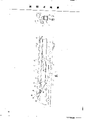
Figure 1 shows that a hoisting crane of the present invention, be under the folded state so that transportation.
Fig. 2 is II among Fig. 1-II section-drawing, shows pillar stiffener and folds up so that the mutual alignment between each section of crane arm of transporting.
Fig. 3 shows a hoisting crane, and its telescopic pillar stiffener is holded up, but does not stretch out; Crane arm is in folded state, and it abuts on the pillar stiffener after a vertical axis that winds the assembly that is made of second section of crane arm and top section rotates.
Fig. 4 to Fig. 9 shows some stages that hoisting crane is installed successively.
Hoisting crane when Figure 10 shows pillar stiffener Shu Qi And and stretches out, crane arm all launch and are in the mode of operation of level.
Hoisting crane shown in Figure 11 is in a state can avoiding some obstacle.
Figure 12 shows a state of hoisting crane, can install one or a few crane arm lengthening section from ground additional under this state.
Figure 13 is the schematic perspective view that crane arm folded and launched assembly pulley.
Hoisting crane shown in the figure has a chassis 1 fixing or that roll by known way, and it is by directed device 2 supportings one swivel base 3, and the latter is loaded with a clump weight 4 and two struts 5 and 6 of holding up telescoping shoring post 7.Telescoping shoring post 7 is made up of outer pillar stiffener member 8 and interior pillar stiffener member 9, and the latter can slide in the middle of the former.Telescoping shoring post 7 can level falls and was in travelling position as shown in Figure 1, also can hold up and was in plumbness such as Fig. 3 to shown in Figure 12.Under plumbness, outer pillar stiffener member 8 is locked in the front portion of swivel base 3 around a horizontal shaft 10.Flexible and the blocking device of known support post 7 is not shown on figure, interior pillar stiffener member 9 outside in the pillar stiffener member 8 slip , And remain on the position of rising as shown in figure 10.But interior pillar stiffener member 9 also can be stayed in the pillar stiffener member 8 or be in any position intermediate.
Hoisting crane is equipped with a folding distribute type crane arm 11, forms by three sections that are hinged.Three sections of crane arm 11 are designated as end section 12, second section 13 and top section 14 successively.
According to the present invention, section 12 is hinged with interior pillar stiffener member 9 tops by a horizontal shaft 15 at the bottom of the crane arm, can turn down forward and vertically places-see Fig. 3 to 8 along pillar stiffener 7.Section 12 has a doorframe shape crane arm after poppet 16 at the bottom of the crane arm at its rear portion, the bottom of after poppet is hinged with section 12 at the bottom of the crane arm by horizontal shaft 17, in transportation with when installing, can be folded in that the 18 Shang , And that wind up of section 12 can lock it under the folded state at point 19 places at the bottom of the crane arm.The flexible tension member 20 of a regular length is made up of a cable wire or some rigid chain nodular parts that is hinged, and the top 21 of crane arm after poppet 16 is connected with the point 22 that winds up on 18.
Crane arm top section 14 is hinged with second section 13 of crane arm by a horizontal shaft 41, and this horizontal shaft is on the horizontal surface of lower edge 25 and 42.Crane arm top section is remained on its position by tie-rod 30, has the member (not shown on the figure) of known whole necessity on its free end 43, in order to realize the distribution and the lifting of load.
Hoisting crane is equipped with a lifting capstan winch, by known way and distributes capstan winch and that capstan winch is installed, and is not shown on the figure.The installation capstan winch guarantees the setting of pillar stiffener 7 and stretches out.
In addition, especially as shown in figure 13, hoisting crane is equipped with the folding of a crane arm 11 and launches capstan winch 44, be placed in the back of section 12 at the bottom of the crane arm, a crane arm folds and launches cable wire 45 fixing (on point 46) has horizontal shaft 48 earlier on crane arm front frame 26 tops 34 by lateral-supporting at the top of crane arm after poppet 16 21 Shang , And first pulley 47; Second sister block 49,50 that on crane arm after poppet 16 tops 21, has horizontal shaft 51,52 again by lateral-supporting, this sister block basically with last pulley to directly; Again by axle the 3rd pulley 53 of 54 that has perpendicular to axle 51 and 52, this pulley is placed in after poppet 16 tops 21 and after poppet 16 on the axis of symmetry of after poppet 16 between the hinged place on the section at the bottom of the crane arm 12 17 by crane arm after poppet 16 supporting , And; Route by symmetry turns back on the 4th sister block 55,56 with horizontal shaft 51,52 again, this sister block lateral-supporting on the top 21 of crane arm after poppet 16, and and 49, the 50 coaxial settings of second sister block; Again by having the 5th pulley 57 of horizontal shaft 48, this pulley side is on the top 34 that is bearing in crane arm front frame 26, and coaxial that , And is set is straight with 55,56 pairs on pulley basically with first pulley 47; Then by sister block assembly 58 and 59 by crane arm after poppet 16 tops, 21 Zhi Cheng And and pulley 49,55 and 50,56 coaxial settings; Last cable wire folds and launches on the reel of capstan winch 44 around crane arm.Like this, it is folding and launch assembly pulley 60 that cable wire 45 constitutes a crane arm, and the respective top 34,21 of crane arm front frame 26 and crane arm after poppet 16 is coupled together.
At last, hoisting crane is equipped with the lifting assembly pulley 61 of a crane arm 11 by known way, with the rear portion 62 of swivel base 3 be connected with 66 assemblies that constitute 64 by two rigid supports 65. Rigid support 65 and 66 have one be hinged in termination on the pillar stiffener member 9 top rear portion points 67, and other two terminations are respectively 68 and 69, pivotally attached connecting rod 70 and 71 couples together on 72 putting mutually by two between them.The top of the point that is positioned at its rearmost termination 68 formation bracket components 64 of support 65, and the termination 69 of another support 66 constitutes and the point of connection of tie-rod 73, this tie-rod connects the top 21 of bracket component 64 and crane arm after poppet 16.
Under state shown in Figure 1, telescoping shoring post 7 fell on level attitude, and interior pillar stiffener member 9 is contracted among the outer pillar stiffener member 8.Section 12 is folded on the pillar stiffener 7 at the bottom of the crane arm in being hinged on the pillar stiffener member 9 top points 15, and second section 13 of crane arm is folded each other with crane arm top sections 14 section 12 at the bottom of the crane arm and is in the same place, and they are positioned at the position shown in Fig. 2 section.
From this state, the installation of hoisting crane is by described carrying out hereinafter:
At known installation F/s (not shown on the figure),, capstan winch will comprise that telescoping shoring post 7 that is in contraction state and the assembly that is in the crane arm 11 of folded state hold up and be in plumbness by means of being installed.Outer pillar stiffener member 8 is locked on the point 10 on the swivel base 3.Under this state, will push up section 14 assemblies that constitute around 18 and 28 rotations of winding up by second section 13 of crane arm and crane arm by means of the vertical axis that can extract out (not shown on the figure), it is under the state shown in Figure 3.
Under state shown in Figure 3, second section 13 of crane arm hinged with section 12 at the bottom of the crane arm by means of the horizontal shaft that can extract out 74, and this horizontal shaft is on 18 and 28 the horizontal surface of winding up.Crane arm after poppet 16 folding leans against at the bottom of the crane arm the 18 Shang , And that wind up of section 12 and is locked in a little on 19.The 28 Shang , And that wind up that crane arm front frame 26 folding leans against second section 13 of crane arm are locked in a little on 29.Crane arm top section support 38 foldings are placed on the front of second section 13 of crane arm, the outer shape that the each several part 31,32 and 33 of tie-rod 30 is got corresponding to crane arm section 13 and 14.
In the subordinate phase of installing, pillar stiffener 7 is stretched out, section 12 , And launch crane arm 11 independently and without restriction at the bottom of the lifting crane arm, like this, just can make hoisting crane be in multiple mode of operation, a kind of mounting means that explanation is recommended as Fig. 4 to Fig. 9.
Be at hoisting crane under the situation of state shown in Figure 3, cable wire 45 folded and launch capstan winch 44 from crane arm emit.Like this, on one side by pulley 49,50 and 55,56, another side is by pulley 47 and 57, the assembly pulley 60 that connects crane arm after poppet 16 tops 21 and crane arm front frame 26 tops 34 is unclamped, under the effect of crane arm section 13 and 14 weight own, assembly 13,14 just rotates around jointed shaft 74, until at the bottom of the crane arm the corresponding lower edge 24 of second section 13 of section 12 and crane arm with till 25 termination contacts, as shown in Figure 4.At this moment, crane arm top 14, with the effect of crane arm top section support 38 bonded assembly tie-rods 30 under, around jointed shaft 41 rotations of second section 13 of itself and crane arm and launch.
At this moment, just can insert on the ground connecting the corresponding lower edge 24 of second section 13 of section 12 and crane arm at the bottom of the crane arm and 25 jointed shaft 23.Second section 13 of crane arm just with crane arm at the bottom of section 12 around being one.The cable wire 45 of assembly pulley 60 is folding and launch on the capstan winch 44 settle once from crane arm, can unclamp and extract crane arm front frame 26 is locked in spools 29 on second section 13 of the crane arm.
Under state shown in Figure 5, unclamp the lockout mechanism of crane arm front frame 26, fold and launch capstan winch 44 from crane arm and roll cable wire 45, crane arm front frame 26 is holded up, under the effect of the tie-rod 30 that crane arm top section support 38 is propped up, make crane arm top section 14 rotate and lift then around itself and second crane arm, 13 pivotally attached axles 41.When this finished in stage, crane arm section 13 and 14 Dui Zhi And became one-see Fig. 6 with a latch 75 with them at 28 and 36 the contact point of winding up.
Under this new state, 18 and 28 the horizontal shaft 74 of winding up that connects second section 13 of section 12 and crane arm at the bottom of the crane arm is extracted out, fold and launch the cable wire 45 that capstan winch 44 is emitted assembly pulley 60 from crane arm, incorporate crane arm section assembly 13 and 14 is under the effect of the weight of this assembly own, and section 12 pivotally attached axles 23 rotate at the bottom of itself and crane arm.
Under state shown in Figure 7, crane arm section assembly 13 and 14 be in basically horizontality , And with respect to the crane arm that is in plumbness along telescoping shoring post 7 basically at the bottom of section 12 meet at right angles.Under this state, between 18 and 28 the termination of winding up of second section 13 of section at the bottom of the crane arm 12 and crane arm, load onto the connecting rod 76 of rigidity, section 12 at the bottom of crane arm section 13,14 assemblies and the crane arm is become one.
The cable wire 45 of assembly pulley 60 is folding and launch capstan winch 44 settles once from crane arm, can Song Kai And extract out crane arm after poppet 16 is locked in the axle 19 on the section 12 at the bottom of the crane arm.At this moment directly by assembly pulley 61 and lifting capstan winch, perhaps after handling, interior pillar stiffener member 9 in the outer pillar stiffener member 8 pins down rope by pulling out indirectly, the jointed shaft 67 of bracket component 64 back, pillar stiffener 9 top in it is placed in is rotated, what tensioning connected bracket component 64 and crane arm after poppet 16 tops 21 is connected tie-rod 73, the crane arm after poppet is promptly holded up, till the position of the flexible tie-rod 20 of tensioning-see Fig. 8.
Under this new state, folding and launch the capstan winch 44 tensioning cable wire 45 of assembly pulley 60 once a little from crane arm, can pull down the rigidity connecting rod 76 that section 12 at the bottom of crane arm section 13,14 assemblies and the crane arm is fused by Song Kai And.
Continue to handle the lifting assembly pulley 61 of crane arm 11, section 12 is in horizontality , And to handle crane arm folding and launch assembly pulley 60 at the bottom of crane arm, until three sections 12,13,14 pairs of crane arm 11 until horizontal assignment state.
The respective top 34 of crane arm front frame 26 and after poppet 16 is connected by a flexible tension member 77 with 21, the connection tie-rod of the latter when three sections of crane arm Bei Zhang Jin And is as work when straight-see Figure 10.
Under state shown in Figure 10, continue foldingly and launch capstan winch 44 and handle assembly pulleys 60 by crane arm, assembly 13,14 is lifted with respect to section at the bottom of the crane arm 12, for example can make this operation-see Figure 11 in order to avoid an obstacle 63 that runs in the course of the work.
In addition, as shown in figure 12, fold and launch assembly pulley 60 by crane arm and can need only adjunction one crane arm extension element 78 or some similar members on the termination of crane arm top section 14 simply and need break-down crane from spreading crane arm 11 on the ground.
Like this, just constitute a folding hoisting crane, be equipped with the folding and expansion assembly pulley 60 of crane arm, have rational structure and obviously labour-saving effect.
Obviously, under the mode of operation that launches, carry out and above-mentioned opposite manipulation process, just can fold up hoisting crane fully.
It should be noted that power operated crane arm is folding and launch cable wire 45, with the different conditions of crane arm 11, can be from transferring to another pulley by a pulley each sister block 49,50 and 55,56 of crane arm after poppet 16 tops 21 lateral-supportings.Specifically at Fig. 3 to the situation in each stage shown in Figure 7, cable wire 45 is by pulley 50 and 56.When promoting after poppet 16, cable wire 45 progressively leaves pulley 50 and 56 and transfer on pulley 49 and 55.To the situation in each stage shown in Figure 12, cable wire 45 is by pulley 49 and 55 at Fig. 8.
From the above as can be known, the lifting of crane arm 11 and launch can be under any state that pillar stiffener 7 stretches out, even in the process of stretching out, carry out.Particularly, after pin down under the situation that does not have crane arm lifting assembly pulley on the rope, at F/s, pin down the rope tensioning after between the top 68 that the stretching out of pillar stiffener 7 makes bracket component 64 and the rear portion 62 of swivel base 3, and in subordinate phase, with being applied to the folding of crane arm 11 and launching effect on the assembly pulley 60, crane arm 11 is risen and get the state of certain expansion.
Certainly, the present invention is not limited only to a kind of form of implementation of above-mentioned folding crane arm hoisting crane, and this form proposes as an example.On the contrary, it comprises all modification according to principle of uniformity, particularly can adopt various different structure forms for various flexible tie-rod or collapsible tie- rod 20,30 and 77.
Claims (9)
1, a kind of have by three section (12,13,14) the folding hoisting crane of the crane arm of Zu Chenging, at least has the folding and expansion cable wire (45) of a power operated crane arm, this cable wire is by bracket component (16,26,38) connect section (12) at the bottom of crane arm second section (13) and the crane arm, it is characterized in that: power operated crane arm folding and launch cable wire (45) fixing (at point 46) be placed in crane arm at the bottom of the top (21) of crane arm after poppet (16) on the section (12) go up And and continuing up to from installation the process of mode of operation, be placed in crane arm front frame (26) top on the crane arm second section (13) (34 and crane arm after poppet (16) top (21) between form an assembly pulley in the following manner, promptly on crane arm front frame (26) top (34), have first pulley (47) of horizontal shaft (48) earlier by lateral-supporting; Second pulley (49,50) that on crane arm after poppet (16) top (21), has horizontal shaft (51,52) again by lateral-supporting, this pulley basically with last pulley (47) to directly; Again by being bearing in the 3rd pulley that has on the crane arm after poppet (16) perpendicular to the axle (54) of above-mentioned axle (51,52), this pulley is located substantially in the plane of after poppet (16), is contained on the axis of symmetry of after poppet between the hinge-point (17) of section (12) at the bottom of after poppet top and after poppet and the crane arm; Route by symmetry turns back to lateral-supporting on the 4th pulley on crane arm after poppet (16) top (21) (55,56) again, this pulley and the coaxial setting of second pulley (49,50); Again by five pulley (57) of lateral-supporting on crane arm front frame (26) top (34), this pulley and the coaxial setting of first pulley (47); Assembly by being supported by crane arm after poppet (16) top (21), constitute by two pulleys (58,59) at least at last, this two pulley and the coaxial setting of the second and the 4th pulley (49,55 and 50,56); It is folding and launch on the reel of capstan winch (44) to twist in the crane arm that is positioned at section (12) rear end at the bottom of the crane arm then.
2, according to the described folding hoisting crane of claim 1, it is characterized in that: crane arm after poppet (16) is doorframe shape, its bottom-hinged (at point 17) is on the rear end of section at the bottom of the crane arm (12), after poppet (16) folding leans against at the bottom of the crane arm wind up (18) of section (12) and goes up And and locate to be locked under the state of folding by section (12) at the bottom of the crane arm at point (19), and remain under the upright state by the fixing flexible tension member (20) of a length, this tension member is connected the front portion of section (12) at the bottom of the crane arm with after poppet top (21) and winds up on the point (22) of (18).
3, according to the described Foldable crane of claim 2, it is characterized in that: crane arm front frame (26) is doorframe shape, its bottom-hinged (at point 27) is on the rear end of crane arm second section (13), wind up (28) last And that folding leans against crane arm second section (13) is locked in folding by under the state of crane arm second section (13), this front frame also remains under the upright state by the fixing folding tie-rod (30) of a length, this tie-rod is connected crane arm top section (14) with front frame top (34) and winds up on the point (35) of (36), push up section (14) support (38) top (37) through crane arm in the connection procedure, this support (38) is doorframe shape, and its bottom-hinged (at point 39) is on the front portion of crane arm second section (13).
4, according to the described Foldable crane of claim 3, it is characterized in that: folding tie-rod (30) is by three parts (31,32,33) constitute, form a system, can make crane arm top section (14) folding lean against crane arm second section (13) below, its first (31) is a cable wire, the top (34) of crane arm front frame (26) is connected on the top (37) of crane arm top section support (38), its second and third part constitute one by two connecting rods (32,33) assembly of Gou Chenging, this two connecting rod each with one end hinged each other (at point 40), this assembly connects the wind up point (35) of (36) of the top (37) of crane arm top section supports (38) and crane arm top section (14) with its two ends.
5, according to any described folding hoisting crane in the claim 1 to 4, it is characterized in that: also be equipped with device (75), use so that crane arm second section (13) temporarily is bonded with each other with the termination that crane arm pushes up corresponding the winding up (28 and 36) of section (14).
6, according to the described folding hoisting crane of claim 1, it is characterized in that: front and back support (26,16) corresponding top (34,21) is connected by a flexible tension member (77), and this flexible tension member is slack-free in three sections (12,13,14) of crane arm (11) when directly being in horizontal assignment state.
7, according to the described Foldable crane of claim 1, it is characterized in that: this hoisting crane also includes detouchable connecting rod (76), in order to two sections (12 and 13) at crane arm be in right angle Bu Zhi And when needing in installation, to link into an integrated entity with crane arm at the bottom of section (12) and crane arm second section (13) (18, the 28) termination of winding up accordingly couple together.
8, according to the described folding hoisting crane of claim 1, it is characterized in that: fold and launch in the assembly pulley (60) at crane arm, second pulley and the 4th pulley that are bearing on crane arm after poppet (16) top (21) are sister block (49,50 and 55,56), and crane arm motor-driven cable wire (45) folding and that launch can be transferred on another pulley by a pulley from each sister block.
9, according to the described folding hoisting crane of claim 1, it is characterized in that: crane arm (11) folding and launch assembly pulley (60) can be in order on the ground by extend crane arm (11) and of at least one crane arm lengthening section of adjunction (78) without break-down crane.
Applications Claiming Priority (2)
| Application Number | Priority Date | Filing Date | Title |
|---|---|---|---|
| FR8902866 | 1989-02-28 | ||
| FR8902866A FR2643625B2 (en) | 1988-09-20 | 1989-02-28 | FOLDABLE CRANE WITH BOOM IN THREE ARTICULATED ARTICLES |
Publications (2)
| Publication Number | Publication Date |
|---|---|
| CN1045251A true CN1045251A (en) | 1990-09-12 |
| CN1021427C CN1021427C (en) | 1993-06-30 |
Family
ID=9379380
Family Applications (1)
| Application Number | Title | Priority Date | Filing Date |
|---|---|---|---|
| CN 90101023 Expired - Fee Related CN1021427C (en) | 1989-02-28 | 1990-02-27 | Folding crane with three section jibs articulated each other |
Country Status (4)
| Country | Link |
|---|---|
| CN (1) | CN1021427C (en) |
| CZ (1) | CZ279258B6 (en) |
| DD (1) | DD293094A5 (en) |
| RU (1) | RU2035384C1 (en) |
Cited By (2)
| Publication number | Priority date | Publication date | Assignee | Title |
|---|---|---|---|---|
| CN107720572A (en) * | 2017-11-17 | 2018-02-23 | 长沙理工大学 | The three section folding conveyers that a kind of hoist engine automatically controls |
| CN110642152A (en) * | 2019-10-16 | 2020-01-03 | 长沙理工大学 | Large-span bulk cargo conveying system |
Families Citing this family (2)
| Publication number | Priority date | Publication date | Assignee | Title |
|---|---|---|---|---|
| RU2143513C1 (en) * | 1999-04-27 | 1999-12-27 | Войсковая часть 44535 | Track-laying machine |
| CN114368697B (en) * | 2022-01-27 | 2025-07-18 | 三一汽车起重机械有限公司 | Auxiliary winch self-loading and unloading crane and auxiliary winch self-loading and unloading method |
-
1990
- 1990-02-23 CZ CS90878A patent/CZ279258B6/en unknown
- 1990-02-26 DD DD33815690A patent/DD293094A5/en not_active IP Right Cessation
- 1990-02-27 CN CN 90101023 patent/CN1021427C/en not_active Expired - Fee Related
- 1990-02-27 RU SU4743206 patent/RU2035384C1/en not_active IP Right Cessation
Cited By (3)
| Publication number | Priority date | Publication date | Assignee | Title |
|---|---|---|---|---|
| CN107720572A (en) * | 2017-11-17 | 2018-02-23 | 长沙理工大学 | The three section folding conveyers that a kind of hoist engine automatically controls |
| CN110642152A (en) * | 2019-10-16 | 2020-01-03 | 长沙理工大学 | Large-span bulk cargo conveying system |
| US10994935B1 (en) | 2019-10-16 | 2021-05-04 | Changsha University Of Science And Technology | Large-span bulk material conveying system |
Also Published As
| Publication number | Publication date |
|---|---|
| CS9000878A2 (en) | 1991-07-16 |
| RU2035384C1 (en) | 1995-05-20 |
| DD293094A5 (en) | 1991-08-22 |
| CZ279258B6 (en) | 1995-02-15 |
| CN1021427C (en) | 1993-06-30 |
Similar Documents
| Publication | Publication Date | Title |
|---|---|---|
| RU2145934C1 (en) | Method of and device for mounting tower crane boom | |
| US5897101A (en) | Collapsible engine hoist | |
| US3968884A (en) | Storage means for jib for telescopic boom of mobile crane | |
| BRPI1001533A2 (en) | MAIN FOLDING BOOM ANCHOR AND TRANSPORTABLE GORNID ANCHOR COVERS | |
| US3944082A (en) | Locking means for relatively movable boom sections of boom of mobile crane | |
| US3945333A (en) | Means for storing and connecting jib for telescopic boom of mobile crane | |
| CN1021427C (en) | Folding crane with three section jibs articulated each other | |
| EP1735233B1 (en) | Mobile crane system comprising a mobile crane and an auxiliary device for assembly of a bracing device | |
| US4595108A (en) | Method for stretching and folding extension jib in wheeled type crane | |
| CN113562635A (en) | Crane and crane arm lifting method | |
| US5597081A (en) | Portable crane | |
| KR100600634B1 (en) | Car Mini Crane | |
| CN1028744C (en) | Grue a tour repliable automatiquement | |
| US5224612A (en) | Portable crane | |
| JP2767598B2 (en) | Jib connecting device to the end of the telescopic boom | |
| JPH02117591A (en) | Foldable crane having boom comprising two or three elements connected mutually | |
| CN218539088U (en) | Telescopic frame assembly | |
| US4658972A (en) | Method for stretching and folding extension jib in wheeled type crane | |
| CN1054051A (en) | The Foldable crane that two sections of crane arms or three hinged parts become | |
| US4050586A (en) | Apparatus for raising & lowering a mast and boom on a mobile crane | |
| JP7561829B2 (en) | Telescoping jib with swing-out mast | |
| CN212687422U (en) | Portable hoisting device | |
| JP3043547U (en) | Vehicle lifting equipment | |
| JP2789457B2 (en) | Extension jib to telescopic boom tip | |
| CN112456349A (en) | Crane |
Legal Events
| Date | Code | Title | Description |
|---|---|---|---|
| C06 | Publication | ||
| PB01 | Publication | ||
| C10 | Entry into substantive examination | ||
| SE01 | Entry into force of request for substantive examination | ||
| C14 | Grant of patent or utility model | ||
| GR01 | Patent grant | ||
| C19 | Lapse of patent right due to non-payment of the annual fee | ||
| CF01 | Termination of patent right due to non-payment of annual fee |