Thereby, the objective of the invention is to, a kind of stabilizing arrangement of generator is provided, it is the low-frequency disturbance of stable generator effectively, and is not subjected to the influence of generator output.
In addition, another object of the present invention is, a kind of power stability device is provided, it can be under optimum condition, in from the low frequency of about 0.2Hz to the quite wide scope of the high frequency of about 3Hz (this occurs in the general electrical generator system), damping power fluctuation suitably, and it is not subjected to have usually the The noise of quite high vibration frequency.
For achieving the above object, first aspect of the present invention provides a kind of power stability device that is used for generator, be used for to automatic voltage regulator (3) input voltage regulation signal (e), be used for the terminal voltage of generator is controlled at target voltage (Vo) as auxiliary signal, this device comprises:
The power stabilizer circuit is added to the correction voltage conditioning signal (e) of this automatic voltage regulator (3) in order to calculating;
It is characterized in that also comprising:
Angular acceleration observer (1) is used for angular acceleration difference (Δ as) according at least a stabilization signal Difference Calculation generator estimation of generator; And
This power stabilizer circuit (2) calculates described correction voltage conditioning signal (e) according to the difference value (Δ as) of the angular acceleration of the estimation of being calculated by described angular acceleration observer (1).
Here, the stabilization signal difference of generator is active power difference and angular speed difference.
In addition, angular acceleration observation comprises: the angular acceleration Difference Calculation device of estimation, be used for angular speed difference according to active power Difference Calculation estimation, the phase angle difference of estimation, the damping coefficient of estimation and the active power difference of estimation, thereby obtain the angular acceleration difference of estimation, be used for the reproducing power fluctuation; And active power differential feedback device, be used for calculating the deviation signal between the active power difference of active power difference and estimation, and a deviation signal of calculating is fed back to described angular acceleration difference estimation device.
Can comprise in the angular acceleration Difference Calculation device of the estimation here: the first adder of response active power difference and feedback signal is used for calculating the angular acceleration difference of estimation; First integrator is used for the angular acceleration difference of integration estimation, thereby obtains rate of change of angular; The second integral device is used for the angular speed difference of integration estimation, thereby obtains the phase angle difference of estimation; First multiplier is used for taking advantage of the angular speed difference with a constant, thereby obtains the damping coefficient of estimation; And second multiplier, be used for taking advantage of the phase angle difference of estimation, thereby obtain the active power difference of estimation with a constant.
In addition, active power differential feedback device can comprise: second adder is used for calculating the deviation between the active power difference of active power difference and estimation; And the 3rd multiplier, be used for taking advantage of the deviation of calculating, and the deviation signal of being taken advantage of fed back to the described first adder of described estimation angular acceleration Difference Calculation device (11) with a constant.
In addition, preferably the power stability device also comprises angular speed difference feedback device, and it comprises: the 3rd adder, the deviation between the angular velocity difference that is used for calculating actual angular speed difference and estimation is divided; And the 4th multiplier, be used for taking advantage of the deviation of calculating, and the deviation of being taken advantage of fed back to the described first adder of described estimation angular acceleration Difference Calculation device with a constant.In addition, preferably also comprise angular speed difference feedback device, it comprises: the 3rd adder, and the deviation between the angular velocity difference that is used for calculating actual angular speed difference and estimation is divided, and be connected the 4th adder between described first multiplier and described second multiplier; And the 5th multiplier, be used for taking advantage of the deviation of calculating, and the deviation of being taken advantage of fed back to described the 4th adder of the angular acceleration Difference Calculation device of described estimation with a constant.
In addition, best described power stability device also comprises angular speed difference feedback device, and it comprises: be connected the 4th adder between described first multiplier and described second multiplier; The 8th adder, the deviation between the angular velocity difference that is used for calculating actual angular speed difference and estimated speed is divided; The tenth multiplier is used for deviation with a constant calculations, thus take advantage of deviation feed back to the described first adder of the angular acceleration Difference Calculation device of described estimation; And the 11 multiplier, be used for taking advantage of the deviation of calculating, thereby the deviation of being taken advantage of fed back to described the 4th adder of described estimation angular acceleration Difference Calculation device with a constant.In addition, preferably provide the slender acanthopanax musical instruments used in a Buddhist or Taoist mass of the deviation of calculating between the active power difference of active power difference and estimation, the 8th multiplier is used for taking advantage of with a constant deviation of calculating, thus take advantage of the result impose on described first adder; And the 9th multiplier, be used for a useful constant to take advantage of the deviation of calculating, thus take advantage of the result impose on described the 4th adder.Preferably also provide: the 7th multiplier is used for taking advantage of with a constant phase angle difference of estimation; The 7th adder, be used for calculating generator voltage difference and the phase angle taken advantage of between difference; A lag filter, the difference that is used for lagging behind and calculates; The 6th multiplier is used for multiply by the result who is lagged behind with a constant, and the 6th adder, is used for adding the active power difference of the result of the hysteresis of being taken advantage of and estimation and the result of addition is supplied with described first adder.
In addition, according to a second aspect of the present invention, a kind of power stability device that is used for generator is provided, be used for to automatic voltage regulator input voltage regulation signal as auxiliary signal, thereby the control generator voltage is a target voltage, and this device comprises: one group of observer, and each is assigned to each generator output pulsation frequency, be used for calculating in the following amount at least one: the angular acceleration difference of estimation, the angular speed difference of estimation according in the stabilization signal difference of generator at least one; The active power difference of estimation and the frequency differential for each vibration frequency of estimation, one group of power stabilizer circuit, wherein each is assigned to described one group of of observing, be used for calculating each regulated voltage signal, according at least one carries out described calculating in the following amount: the angular acceleration difference of estimation, the angular speed difference of estimation, the frequency differential that has difference power to divide and estimate of estimation for each vibration frequency, and adder, be used for adding the regulated voltage signal of calculating, added regulated voltage signal is fed to automatic voltage regulator.
The stabilization signal difference of the generator here is: active power difference, angular speed difference, and the frequency differential of generator.
Described one group of observer here is preferably: first observer, be used for reproducing low-frequency fluctuation frequency mode (0.5Hz or lower), second observer is used for reproducing intermediate wave dynamic frequency mode (approximately 1Hz), and the 3rd observer, be used for reproducing high-frequency fluctuation frequency mode (2Hz or higher).
In addition, preferably described one group of observer is: first observer, be used for reproducing first frequency electro-mechanical wave frequency mode (for example 3Hz), and second observer, be used for reproducing second frequency mechanical oscillation frequency mode (for example 5Hz).
In addition, the preferably described observer that is used for estimating the angular speed difference is distributed to the fluctuation mode than low frequency, and relevant with the described power stability circuit of angular velocity difference somatotype; And the described described observer that is used for calculating the angular acceleration difference is assigned to the fluctuation mode of upper frequency, and relevant with the described power stability circuit of effective power difference type.
In addition, best described power stability device also comprises a plurality of switching devices, and each is distributed to described observer and described power stability circuit each respectively, is used for selecting at least one described observer and at least one corresponding described power stability circuit.
In a first aspect of the present invention, when detecting the active power difference that causes by power fluctuation, by the power fluctuation of estimation angular acceleration Difference Calculation device simulation and forecast.The angular acceleration difference of estimation is sent to the power stability circuit.According to the angular acceleration difference of estimation, power stability circuit output voltage conditioning signal is given the automatic circuit adjuster.
In addition, active power differential feedback device obtains the active power difference of estimation and the deviation between the actual active power difference, and goes to take advantage of the gained deviation with a suitable gain, estimates angular acceleration Difference Calculation device thereby the deviation of being taken advantage of fed back to.With the same manner, angular speed difference feedback device obtains the angular speed difference of estimation and the actual angular velocity difference deviation between dividing, and goes to take advantage of this deviation with a suitable gain, thereby the deviation that feedback is taken advantage of is to estimating angular acceleration Difference Calculation device.Utilize these to handle, just can proofread and correct between the estimated value that obtains by simulation and the actual value As time goes on and the deviation that increases.
Thereby, because can be added on the power stability circuit, just can eliminate low-frequency noise, otherwise when effective difference power branch directly was added to the power stability circuit, this noise can cause problem with the angular acceleration of high accuracy estimation.
According to second aspect of the present invention, one group of observer is assigned to one group of vibration frequency mode respectively, and calculate in the following amount at least one: the rate of angular acceleration of estimation, the angular speed difference of estimation, the active power difference of estimation and the frequency differential of estimation.Each of these estimated values is supplied to the power stability circuit that is assigned to each observer, thereby calculates the regulated voltage signal corresponding to each fluctuation mode.These regulated voltage signals are given automatic voltage regulator as regulated voltage signal then by the adder addition.
Thereby (0.5Hz or lower for example, approximately 1Hz and 2Hz are higher) can obtain regulated voltage signal respectively for each vibration frequency.
In addition, when one group of observer is second observer of first observer and being used to that is used to reproduce the electro-mechanical wave frequency mode (for example 3Hz) of the first frequency mechanical oscillation frequency mode (for example 5Hz) of reproducing second frequency, can from the electro-mechanical wave frequency component, isolate the mechanical oscillation radio-frequency component effectively.
In this case, when the observer that is used to estimate the angular speed difference is assigned to lower frequency fluctuation mode and when relevant with the power stability circuit of angular velocity difference somatotype, and when being used to estimate that the angle quickens the observer of difference and be assigned to higher frequency fluctuation mode and when relevant with the power stability circuit of active power difference type, can realize optimum phase compensation according to Bode diagram.
In addition, each is distributed to each observer and each power stability circuit respectively when a plurality of switching devices, so that when selecting the corresponding power stability circuit of at least one observer and at least one, just can select at least one required observer and at least one power stability circuit accordingly mutually according to situation.
The embodiment of generator power stabilizing arrangement of the present invention (PSS) is described with reference to the accompanying drawings.
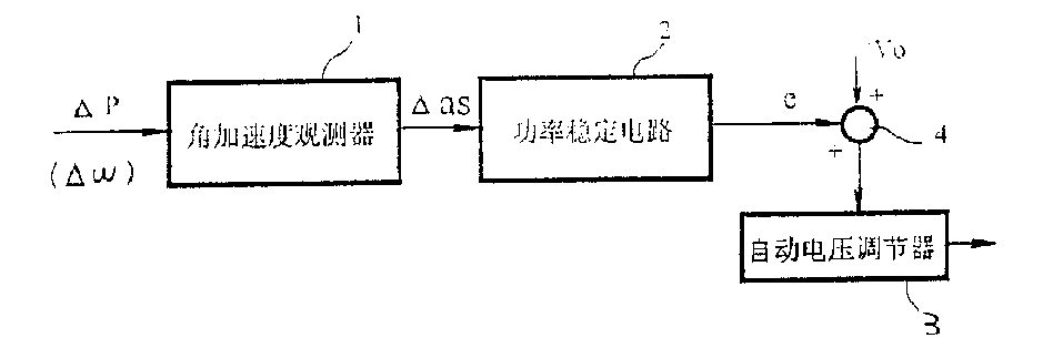
Fig. 1 represents the basic embodiment of power stability device of the present invention, and it comprises angular acceleration observer 1 and power stability circuit 2.The active power difference delta P of angular acceleration observer 1 response generator or the angular speed difference Δ ω of generator calculate the angular acceleration difference delta as (s represents estimated value) of estimation.In addition, according to the estimation angular acceleration difference delta as that calculates, power stability circuit 2 calculating voltage conditioning signal e.The regulated voltage signal e of this calculating is supplied to adder 4.Adder 4 making alive conditioning signal e and target voltage Vo.This is put on automatic voltage regulator 3 by signal.According to regulated voltage signal e and target voltage Vo, the excitatory value of automatic voltage regulator 3 control generators makes that the terminal voltage of generator can be controlled on the target voltage Vo under phase compensation.
As mentioned above, according to power stability device of the present invention, provide angular acceleration observer 1 to be used for according to the active power difference delta P of generator or the angular acceleration difference delta as of angular speed difference Δ ω estimation generator.The angular acceleration difference delta as of this estimation is sent to power stability circuit 2 as stabilization signal.In addition, angular acceleration observer 1 has at least one circuit and is used for reproducing power fluctuation, so that estimation active power difference delta Ps and angular speed difference Δ ω s.In addition, the deviation between the angular speed difference Δ ω of the generator angular speed difference Δ ω s of deviation between the power difference delta P of the active power difference delta Ps of angular acceleration observer 1 calculating estimation and actual measurement and/or estimation and actual measurement.The deviation of calculating be multiply by a gain respectively, and the input side that is fed back angular speed observer 1 then is used for the reproduction of power fluctuation.
The following describes the accurately principle of estimated acceleration difference delta a of angular acceleration observer 1.Has the above-mentioned circuit that is used for the reproducing power fluctuation according to angular acceleration observer 1 of the present invention.Therefore, when the power fluctuation reproducing circuit detected the active power difference delta P that the power fluctuation by reality causes, it can remove simulated power fluctuation Δ Ps according to the active power difference delta P that detects.
Here, if power fluctuation is simulated simply, the vibration frequency and the damping ratio of actual power fluctuation will depart from the value of As time goes on being simulated by the power fluctuation reproducing circuit slightly, like this, the deviation between predicted value (simulation gained) and the actual value (observation station gets) in time passing and increase.Therefore, in this embodiment, deviation among the active power difference delta P of the generator between estimated value and actual value and the angular speed difference Δ ω be multiply by a suitable gain respectively, just feed back to power fluctuation reproducing circuit (simulator circuit) then, thereby the phase place and the amplitude of estimated value that just can the correcting reproducing circuit make it near actual value.This theory has been established as observer theory or Ka Erman filter theory in control theory.
In above-mentioned power fluctuation reproducing circuit, to remove outside the main mode of vibration of circuit, circuit is otherwise worked hardly, thereby can be effectively and accurately eliminate low-frequency noise.In addition, different with band pass filter, phase place is lagged behind hardly.
Therefore, when accurately the angular acceleration difference of estimation is used by power stability circuit 2 according to above-mentioned principle, just can eliminate low-frequency noise, otherwise this noise just can cause problem when meritorious difference power branch is directly used.
[first aspect]
(first implements)
Fig. 2 is the circuit diagram according to first embodiment of the first aspect of angular acceleration observer of the present invention.
In Fig. 2, angular acceleration observer 1 comprises estimation angular acceleration Difference Calculation device 11, and active power differential feedback device 12.
Estimation angular acceleration Difference Calculation device 11 comprises first adder 4a, first integrator 5a, second integral device 5b, first (ratio) multiplier 6a, and second (ratio) multiplier 6b.In addition, angular acceleration differential feedback device 12 comprises second adder 4b and the 3rd (feedback oscillator) multiplier 7.
Angular acceleration difference estimation calculation element 11 reproduces (i.e. expression) power fluctuation (being mode of vibration) according to the active power difference delta P of generator.In other words, estimation calculation element 11 is by the angular speed difference Δ ω s of first integrator 5a by the angular acceleration difference delta as calculating estimation of reduction of fractions to a common denominator estimation, by calculate the phase angle difference delta δ s of estimation by the angular speed difference Δ ω s of second integral device 5b integral and calculating, by multiply by the phase angle difference delta δ s of estimation with K1 (constant), calculate the active power difference delta Ps of estimation with the second multiplier 6b.In addition, angular acceleration difference estimation calculation element 11 multiply by the angular speed difference Δ ω s of estimation by the first multiplier 6a with D (constant), obtains damping force (coefficient) the value D Δ ω s of estimation.
Active power differential feedback device 12 is by the deviation between the active power difference delta Ps of second adder calculating active power difference delta P and estimation, and the deviation of calculating be multiply by L1 (feedback oscillator), and the deviation that obtains is fed back to the first adder 4a of angular acceleration difference estimation calculation element 11 by the 3rd multiplier 7a.
In first embodiment of Fig. 2, the reproducing circuit of power fluctuation comprises first integrator 5a, and the second integral device 5b and the first multiplier 6a make and can represent vibration with the power fluctuation mode.
Thereby, in first embodiment, can realize simple angular acceleration observation, and not need any angular acceleration detector.
(second embodiment)
Fig. 3 represents second embodiment according to the first aspect of angular acceleration observer of the present invention.The difference of first embodiment of it and Fig. 2 is that angular speed difference Δ ω is used as measuring-signal except that active power rate of change Δ P.In other words, angular acceleration observer 1 also comprises the angular speed difference feedback device 13 that is made of the 3rd adder 4c and the 4th multiplier 7b.Deviation between the rate of change of angular Δ ω that the 3rd adder 4c calculating is measured and the angular speed difference Δ ω s (output of first integrator 5a) of estimation.The result who adds multiply by L2 (feedback oscillator) by the 4th multiplier 7b, feeds back to first adder 4a then.
(the 3rd embodiment)
Fig. 4 represents the 3rd embodiment of the first aspect of angular acceleration observer of the present invention.The difference of it and second embodiment shown in Figure 3 is that the deviation between the angular speed difference Δ ω s of the angular speed difference Δ ω (output of first integrator 5a) of measurement and estimation is fed back to the output (not feeding back to first adder 4a) of first integrator 5a.
In other words, angular acceleration observer 1 also comprises the angular speed difference feedback device 13 that is made of the 3rd adder 4c, the 5th multiplier 7c and the 4th adder 4d.Deviation between the angular speed difference Δ ω that the 3rd adder 4c calculating is measured and the angular speed difference Δ ω s (output of first integrator 5a) of estimation.The result who adds multiply by L3 (feedback oscillator) by the 5th multiplier 7c, feeds back to the 4th adder 4a that is connected between the first and second integrator 5a and the 5b then.
In the second and the 3rd above-mentioned embodiment, though have the angular velocity detector that is used to detect angular speed difference Δ ω, the adjustment of gain is quite easy, and this is quite little because of feedback oscillator (need be conditioned).
(the 4th embodiment)
Fig. 5 represents the 4th embodiment according to the first aspect of angular acceleration observer of the present invention.The difference of it and first embodiment shown in Figure 2 is that except that active power difference delta P, angular speed difference Δ ω is used as measuring-signal; Measure and be fed back first adder 4a (in second embodiment) and the 4th adder 4d (as the 3rd embodiment) with angular speed difference Δ ω; And additional once lag filter 8, except that simple secondary mode of oscillation (as first to the 3rd embodiment), be used for representing excitatory hysteresis.
In a word, in this embodiment, the active power difference delta Ps both of the angular speed difference Δ ω of estimation and estimation proofreaies and correct according to the deviation between measured value (Δ ω or Δ P) and the estimated value (Δ ω or Δ Ps) respectively.
In more detail, angular acceleration observer 1 also comprises the 5th to the 7th adder 4e to 4g, and the 6th to the 11st multiplier 6c, 6d and 7d are to 7g, and a lag filter 8.
Active power difference delta P is added on the 5th adder 4e.Deviation between the active power difference delta Ps of slender acanthopanax musical instruments used in a Buddhist or Taoist mass 4e calculating estimation and the actual active power difference delta P.The result who adds multiply by L4 by the 8th multiplier 7d, goes into then to first adder 4a, replaces actual active power difference delta P.In same mode, institute adds the result and multiply by L5 by the 9th multiplier 7e, inputs to the 4th adder 4d then.
On the other hand, the deviation between the angular speed difference Δ ω s (output of the 5th integrator 5a) of the angular speed difference Δ ω of the 8th adder 4h calculating measurement and estimation.L6 (feedback oscillator) be multiply by by the 10th multiplier 7f in institute in addition result, feeds back to first adder 4a then.Institute adds the result and also multiply by L7 (feedback oscillator) by the 11st multiplier 7g, feeds back to the 4th adder 4d that is connected between the first and second integrator 5a and the 5b then.
In addition, the output Δ δ s of second integral device 5b multiply by K1 by second multiplier, feeds back to the 6th adder 4f then.In addition, the output Δ δ s of second integral device 5b multiply by K4 by the 7th multiplier 7d, feeds back to the 7th adder 4g then.The 7th adder 4g calculates the result of calculation of multiplier 6d and the deviation between the generator voltage difference delta E, and feeds back to the 6th adder 4f by second order lag filter 8 and the 6th multiplier 6c (having an input gain K2).
In this embodiment, because used the module that is called " generator dynamic stability piece ", describedly can the most accurately represent the fluctuation mode in the above-described embodiments, as long as the system condition of initial setting is constant.In addition, though the deviation between actual value and the estimation projection value is used to angular acceleration difference delta a and angular speed difference Δ ω, deviation between the two also can be used for proofreading and correct the state of a lag filter 8.In this case, feedback oscillator can easily be obtained, as Kalman filter.
Fig. 6 to Fig. 8 is for utilizing the angular acceleration (as) of angular acceleration observer 1 estimation that analog result obtained of the angular acceleration (a) of conduct reality from the short period (high frequency) to long period (low frequency).Though Fig. 6 represents the amplitude of (high frequency) estimated value (as) in the short period slightly less than the amplitude of measured value (a), both phase places are all coincide well.In addition, the analog result in cycle during Fig. 7 represents (intermediate frequency), Fig. 8 represents the analog result of long period (low frequency).In both cases, can high accuracy estimation amplitude and phase place.As mentioned above, in the 4th embodiment, can estimate angular acceleration (as) with high accuracy.
As mentioned above, in power stability device according to generator of the present invention, because angular acceleration difference delta a can synchronously estimate with angular speed difference Δ ω, and because regulated voltage signal e can obtain according to the rate of angular acceleration Δ as of estimation, just can when changing, suppress generator loading power fluctuation most effectively, and the control of must be not any not unnecessary power stability device.
In addition, even when the power fluctuation cycle is grown to 0.3Hz, also there is significant effect, makes that macrocyclic power fluctuation can be by damping effectively, because the readjustment time of readjustment filter also is determined longlyer.
[second aspect]
The second aspect of power stability device of the present invention is described below with reference to Fig. 9 to Figure 13.In second aspect, the multimode observer that is made of a plurality of angular acceleration observers is provided with corresponding to a plurality of predetermined electric power fluctuation modes.
(first embodiment)
Fig. 9 represents first embodiment according to the second aspect of power stability device of the present invention, and it is made of multimode observer 1A and multimode power stabilizer circuit 2A, and the former has a plurality of observer 1a to 1n, and the latter has a plurality of power stability circuit 2a to 2n.A plurality of observer 1a each in the 1n is assigned to each mode (frequency) in a plurality of power fluctuation modes.
Use effective power difference delta P, angular speed difference Δ ω, and frequency differential Δ f is as the stabilizer signal differential.Therefore, according to one in these stabilizer signal differentials at least, each observer 1a calculates effective difference delta Ps1 of estimation respectively to Δ Psn to 1n, the angular acceleration difference delta as1 of estimation is to Δ asn, the angular speed difference Δ ω s1 of estimation in the frequency differential Δ fs1 of Δ ω sn and estimation and the Δ fsn.
The circuit 2a of the power stability of our 2A of multimode power stabilizer electricity offers the observer 1a of multimode observer 1A to 1n to 2n with each self-corresponding relation, be used for according to the effective difference delta Ps1 that estimates to Δ Psn, the angular acceleration difference delta as1 of estimation is to Δ asn, at least one in to the frequency differential Δ fs1 of Δ ω sn and estimation to Δ fsn of the angular speed difference Δ ω s1 of estimation calculated corresponding to each each regulated voltage signal in a plurality of power fluctuation modes.
These power stabilizer circuit 2a to the regulated voltage signal (output) of 2n and target voltage V0 by adder 4 additions as calculating voltage conditioning signal e, be sent to automatic voltage regulator 3 then.According to regulated voltage signal e and target voltage V0, the excitatory value of automatic voltage regulator 3 control generators, thus make the terminal voltage of generator can be controlled at target voltage V0.
Here, according to power stability device of the present invention, multimode observer 1A reproduces several power fluctuations.In more detail, multimode observer 1A has such function, promptly calculates the active power difference delta Ps of estimation, the angular acceleration difference delta as of estimation, the frequency differential Δ fs of the angular speed difference Δ ω s of estimation and estimation, each is corresponding to each power waves mode; Deviation between the active power difference delta Ps of calculating estimation and the actual power differential signal Δ P of measurement, deviation between the angular acceleration difference delta as of calculating estimation and the angular acceleration differential signal Δ a of measurement, deviation between the angular speed difference Δ ω s of calculating estimation and the angular velocity difference sub-signal Δ ω of measurement, and the deviation between the frequency differential signal delta f of the frequency differential signal delta fs of calculating estimation and measurement; And multiply by each input side that feeds back to each observer 1I after each deviation signal by each gain.As mentioned above, multimode observer 1A can be separately and is detected each (without any phase lag) in a plurality of power fluctuation modes simultaneously.
For example, shown in Figure 2 as reference, each observer 1I comprises first adder 4a, and its response active power difference delta P and other feedback signal is used for calculating the angular acceleration difference delta as of estimation; First integrator 5a is used for the angular acceleration difference delta as of integration estimation, thereby obtains angular speed difference Δ ω s; Second integral device 5b is used for the angular speed difference Δ ω s of integration estimation; Thereby obtain the phase angle difference delta δ s of estimation; The first multiplier 6a is used for multiply by the angular speed difference with a constant D, thereby obtains damping force (coefficient) the D Δ ω s of estimation; And the second multiplier 6b, be used for multiply by constant K of phase angle difference delta δ s of estimation
1Thereby, the active power difference delta Ps of acquisition estimation, or the like.In addition, each observer 1i comprises second adder 4b, is used for calculating the deviation between the active power difference delta Ps of active power difference delta P and estimation; And the 3rd multiplier 7a, be used for a constant K
1Multiply by the deviation of calculating, take advantage of deviation signal feed back to first adder 4a.
As mentioned above, in above-mentioned power fluctuation reproducing circuit, can be effectively and accurately estimate the dry sound of low frequency, because this circuit is not operated under the mode outside its main oscillations mode.In addition, different with the logical device of the logical filter of band, phase place is lagged behind hardly.Therefore, in the multimode observer 1A that has corresponding to the observer 1i of each prime power fluctuation mode, can accurately detect every kind of mode, and not be subjected to the influence of alternate manner and do not have phase lag.
Here as the example of multimode observer 1A, the following describes and have three observer 1a, 1b and 1c and three power stability circuit 2a, the electrical power stabilization device of 2b and 2c.In this example, observer 1a is used to be lower than the low frequency power fluctuation of the model frequency of shaking of 0.5Hz; Observer 1a is used to be lower than the low frequency power fluctuation of the frequency of oscillation of 0.5Hz; Observer 1b is used for the intermediate frequency power fluctuation of the frequency of oscillation of big Hz; And observer 1c is used to be higher than the high frequency power fluctuation of the model frequency of shaking of 2Hz.
In practice, preferably low frequency power fluctuation mode observes 1a be set to 0.3Hz frequency of oscillation mode; Intermediate frequency power fluctuation mode observer 1a is set to 1Hz frequency of oscillation mode; High frequency power fluctuation observer 1a is set to the 3Hz model frequency mode of shaking.
Therefore, in this case, the DeMello/ (parameter K of Concordia model
1, K
2..., K
6And damping ratio D is defined as independently (0.3,1 and 3Hz) suitably in three power fluctuation modes each.Usually, because these parameters are by the system impedance function representation, so three frequencies of oscillation can be determined by the impedance that determines these systems suitably.When this model where applicable, can set up following relation to each mode:
Δa=-ΔTe-DΔω
ΔTe=K
1Δδ+K
2E′
q
Wherein:
Δ a: the angular acceleration difference of generator
Δ ω: the angular speed difference of generator
Δ δ: phase angle difference
The output of U:PSS
Δ T
e: electric torque gradient
E '
q: q axle transition counter voltage
D: damping constant
M: inertia constant
T '
Do: the transition constant of field circuit
K
1-K
AVR: constant
Above-mentioned formula can be organized into following state equation:
X
i=A
iX
i+B
iU
i
Y
i=C
iX
i Wherein, X represents state value; Y represents measured value; U represents the output of PSS.In addition, A, B and C are the constant matricess of determining by each mode.In addition, subscript i representation mode kind.
Above-mentioned knownly be established as a kind of state equation of mode.But, in the present embodiment, because three kinds of power fluctuation modes (0,3,1 and 3Hz) are arranged, for the used portion's power fluctuation mode of multimode observer 1, condition mode can be expressed as follows:
X=Ax+Bu
Y=Cx
Therefore, multimode observer 1 can be expressed as follows according to above-mentioned state equation: X
s=AX
s+ Bu+L (y-CX
s)
Wherein x represents state value; Y represents measured value; 9 (OK) * 2 (row) matrixes of the feedback oscillator of L representative expression observer.Do not calculated the Kalman filter though this matrix does not resemble, can be determined matrix so yet, even the value of estimation concentrates in together.Specifically, when being difficult to regulate all elements of 9 (OK) * 2 (row) matrixes, L can determine in this way, i.e. the basic status of a correction generator (for example acceleration difference delta a or angular speed difference Δ ω).In the power stability device of above-mentioned structure, the acceleration difference delta asi (i=1 of each estimation of each power fluctuation mode, 2,3) and the estimation speed difference delta ω si (i=1,2,3) from multimode observer 1A, taken out, be sent to then each power stabilizer circuit 2A that is adjusted to optimum state.In other words, be adjusted to the power stabilizer circuit 2a of 0.3Hz power fluctuation mode according to the speed difference delta ω s1 operation of calculating.On the other hand, be adjusted to 1 to two power stabilizer circuit 2b of 3Hz power fluctuation mode and 2c respectively according to the acceleration difference delta as2 and the Δ as3 operation of estimation.What the circuit of three power stabilities was regulated like this reasons are as follows:
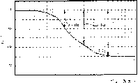
Consider that herein single generator is connected in the situation of infinite busbar system.Lag behind from the transfer function of the electric moment of torsion difference delta of outputing to of PSS Te, shown in Figure 10 (a) and 10 (b), they are Bode diagram of the transmission characteristic of expression field circuit.Figure 10 (a) is a gain-frequency characteristic, and Figure 10 (b) is phase place-frequency characteristic.Because as mentioned above, field circuit lags behind, and can obtain the damping force (coefficient) of resistance power fluctuation by this hysteresis of compensation, in other words, by the electric moment of torsion difference delta of such change Te, makes itself and angular speed difference Δ ω synchronous.Thereby according to the cycle (frequency) of power fluctuation, optimum phase is repaid difference.In addition, too big phase compensation is also bad, because high-frequency noise also has been exaggerated.Therefore, angular acceleration difference delta a (90 ° of its phase advance angle speed difference delta ω) be used to power stability circuit 2b and 2c (to 1 and the high-frequency mode of 3Hz provide), they need big phase compensation (seeing Figure 10 (b)) respectively, so that reduce the degree of compensation of big leading phase.On the other hand, angular speed difference Δ ω is used to power stabilizer circuit 2a (for the low frequency mode of 0.3Hz provides), and it does not need big phase compensation (seeing Figure 10 (b)).As these three power stabilizer circuit 2a, three outputs of 2b and 2c just can obtain last regulated voltage signal e during by adder 4 additions.As mentioned above, in above-mentioned power stability device, provide one group of observer 1A and one group of observer circuit 1B like this, making can be in the fluctuation of the system of any frequency mode of damping under the optimum condition (being considered usually).
(second embodiment)
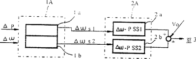
Figure 11 represents second embodiment according to the second aspect of power stability device of the present invention.In the present embodiment, multimode observer 1A is by the power fluctuation mode observer 1a that is used to observe the generator electro-mechanical wave be used to observe the mechanical oscillation mode observer 1b of generator mechanical oscillation to constitute.This is because such situation is arranged, and power fluctuation is promptly not only arranged in active power difference delta P but also mechanical wave (vibration) is arranged.In this case, have only the mechanical wave that need be removed from active power difference delta P, to be separated as the mechanical oscillation component.As a result, just can remove the higher harmonics noise that produces owing to mechanical oscillation, this so far noise causes problem always in Δ ω PSS or Δ fPSS.
In more detail, the observer 1a of multimode observer 1A separates electric power (electricity) fluctuation that is included in the generator power fluctuation, calculating is corresponding to the angular speed difference Δ ω s1 of the estimation of described power fluctuation, and it is outputed to multimode power stability circuit 2A (the stabilizer circuit 2a of Δ ω-PSS).In same mode, the observer 1b of multimode observer 1A separates the mechanical oscillation in the power fluctuation that is included in generator, calculating is corresponding to the angular speed difference Δ ω S2 of the estimation of described mechanical oscillation, and it is outputed to multimode power stability 10 circuit 2A (the stabilizer circuit 2b of Δ ω-PSS).In this case, the frequency of the power fluctuation that is calculated by observer 1a is set as 1Hz or 3Hz, and the mechanical oscillation frequency of being calculated by observer 1b is set as for example 5Hz or higher.The transfer function of mechanical oscillation mode in this case, generally can be represented by the formula:
Here, in the mode identical with the situation of first embodiment, power fluctuation mode and mechanical oscillation mode are bonded to each other, thereby obtain a state equation, and constitute multimode observer 1A according to the mode of combination.Press the rate of change of angular Δ ω s of the multimode observer 1A estimation estimation of above-mentioned formation, and it is inputed to Δ ω-PSS.In this embodiment, mechanical oscillation are separated from power fluctuation, and the rate of change of angular Δ ω s that therefore can obtain to estimate, comprising minimum machinery noise component.
The result, can solve the such problem that in the Δ ω-PSS of routine, exists so far, promptly when using big advance angle to carry out phasing, be included in that machinery noise is exaggerated among the angular speed difference Δ ω, thereby cause the generator shaft vibration for the hysteresis of compensating field circuit.
In the second above-mentioned embodiment, though Δ ω-PSS is used as power stabilizer circuit 2A, above-mentioned same situation can be applied to the Δ f-PSS of frequency of utilization difference delta f.In addition, in general, though the frequency of power fluctuation mode is 1Hz, have such situation, promptly when the impedance between two adjacent generators was low, approximately the 3Hz vibration can cause problem.In this case, second embodiment is effectively, especially because the power fluctuation mode can be separated from mechanical mode of vibration or vice versa (in the power stability device at least in the prior art is impossible).
(the 3rd embodiment)
Figure 12 represents the 3rd embodiment of a second aspect of the present invention.The characteristics of this embodiment are, use the angular speed difference power stabilizer circuit (2a of Δ ω-PSS) for power fluctuation (in quite low frequency mode), for mechanical oscillation (quite high frequency mode), use the active power differential power stabilizing circuit (2b of Δ-PSS).Be set to about the power fluctuation mode of 1Hz according to Δ ω-PSS 2a of Δ ω s, be set as the mechanical oscillation mode of 3Hz according to the Δ P-PSS of Δ as.This is because when vibration frequency is 3Hz, be applicable to the Δ P-PSS (it with respect to Δ ω leading 90 degree) of employing based on Δ as, because need big phase advance angle compensation (about 90 degree are seen Figure 10 (b)).In other words because when 3Hz compensation phase advance angle be difficult to carry out with Δ ω-PSS, so approximately short-period fluctuation of 3Hz is separated and is compensated by Δ P-PSS, Δ P-PSS does not require big phase advance angle.
In a word, in the 3rd example, multimode observer 1A is by the first observer 1a of the power fluctuation that is used for observing about 1Hz and be used for observing second observer 16 of the mechanical oscillation of about 3Hz to constitute.
The angular speed difference Δ ω s of the estimation that is obtained by the first observer 1a is sent to the angular speed difference power stability circuit of multimode power stability circuit 2, and (2a of Δ ω-PSS), the angular acceleration difference delta as of the estimation that is obtained by the second observer 1b is sent to active power rate of change power stabilizer circuit (Δ P-PSS) 2b of multimode power stability circuit 2.
The result, for machinery and electric two kinds of vibrations, can both under optimum condition, realize phase compensation, because the approximately mechanical oscillation of 3Hz (it needs big relative advance angle compensation) can be separated, and because separated short-period mechanical oscillation can be compensated (it does not need big phase advance angle compensation) by Δ P-PSS.
(the 4th embodiment)
Figure 13 represents the 4th embodiment of second aspect present invention.In this embodiment, in multimode observer 1A, provide switching device 9A, be used for selecting a plurality of observer 1a with a plurality of power fluctuation mode relative set to one of 1n, in addition, in multimode power stabilizer circuit 2A, provide another switching device 9B, be used for selecting in the 2n suitable one corresponding to a plurality of stabilizer circuit 2a of selection mode, these two switching device 9A and 9B form the multichannel interlock switch.
In the generator operation of reality, there is a kind of situation, promptly do not need to observe a plurality of power fluctuation modes.Especially when in fact not observing many power fluctuation modes perhaps during multimachine tool mode of vibration in generator operation, according to situation, it is suitable only selecting needed frequency mode, because all need complicated calculating for every kind of vibration or fluctuation mode person.Therefore, when switching device 9A and 9B are provided when being used for eliminating unwanted mode, can realize the power stability device of further optimizing.
As mentioned above, aspect second of the present invention in, can use multimode observer separative power fluctuation mode, can be thereby make according to required power fluctuation mode or situation, best multimode power stability system is provided, and therefore, total energy obtains to make the optimum phase compensation of power stability.In addition, obtain best gain in all alternate total energys.
In addition, because the multimode observer is made of power fluctuation observer and mechanical wave observer, so that make power fluctuation and mechanical wave separated from one another, just can reduce the angular speed difference Δ ω that is included in the power fluctuation mode so far or the machinery noise among the frequency differential Δ f effectively.