CN1062030A - Ignition device - Google Patents
Ignition device Download PDFInfo
- Publication number
- CN1062030A CN1062030A CN91111269A CN91111269A CN1062030A CN 1062030 A CN1062030 A CN 1062030A CN 91111269 A CN91111269 A CN 91111269A CN 91111269 A CN91111269 A CN 91111269A CN 1062030 A CN1062030 A CN 1062030A
- Authority
- CN
- China
- Prior art keywords
- nozzle
- gas injection
- cover
- injection nozzle
- gas
- Prior art date
- Legal status (The legal status is an assumption and is not a legal conclusion. Google has not performed a legal analysis and makes no representation as to the accuracy of the status listed.)
- Granted
Links
- 239000007789 gas Substances 0.000 claims abstract description 90
- 238000002347 injection Methods 0.000 claims abstract description 52
- 239000007924 injection Substances 0.000 claims abstract description 52
- 239000000567 combustion gas Substances 0.000 claims abstract description 22
- 239000004020 conductor Substances 0.000 claims abstract description 22
- 238000003860 storage Methods 0.000 claims abstract description 22
- 230000006872 improvement Effects 0.000 claims abstract description 3
- 230000008676 import Effects 0.000 claims description 5
- 238000007599 discharging Methods 0.000 abstract description 4
- 230000004888 barrier function Effects 0.000 description 5
- 230000015556 catabolic process Effects 0.000 description 4
- 230000009471 action Effects 0.000 description 2
- 239000011810 insulating material Substances 0.000 description 2
- 230000009545 invasion Effects 0.000 description 2
- 239000002184 metal Substances 0.000 description 2
- 238000002156 mixing Methods 0.000 description 2
- 230000001105 regulatory effect Effects 0.000 description 2
- 238000007789 sealing Methods 0.000 description 2
- 239000011343 solid material Substances 0.000 description 2
- 230000003321 amplification Effects 0.000 description 1
- 230000015572 biosynthetic process Effects 0.000 description 1
- 235000019504 cigarettes Nutrition 0.000 description 1
- 238000005520 cutting process Methods 0.000 description 1
- 238000000354 decomposition reaction Methods 0.000 description 1
- 230000002950 deficient Effects 0.000 description 1
- 238000010586 diagram Methods 0.000 description 1
- 230000005284 excitation Effects 0.000 description 1
- 239000000446 fuel Substances 0.000 description 1
- 238000009434 installation Methods 0.000 description 1
- 238000004519 manufacturing process Methods 0.000 description 1
- 239000000463 material Substances 0.000 description 1
- 239000000203 mixture Substances 0.000 description 1
- 238000003199 nucleic acid amplification method Methods 0.000 description 1
- 239000004033 plastic Substances 0.000 description 1
- 229920003023 plastic Polymers 0.000 description 1
- 238000003825 pressing Methods 0.000 description 1
- 239000011347 resin Substances 0.000 description 1
- 229920005989 resin Polymers 0.000 description 1
- 230000004044 response Effects 0.000 description 1
- 239000007921 spray Substances 0.000 description 1
- 230000003313 weakening effect Effects 0.000 description 1
Images




Classifications
-
- F—MECHANICAL ENGINEERING; LIGHTING; HEATING; WEAPONS; BLASTING
- F23—COMBUSTION APPARATUS; COMBUSTION PROCESSES
- F23Q—IGNITION; EXTINGUISHING-DEVICES
- F23Q2/00—Lighters containing fuel, e.g. for cigarettes
- F23Q2/28—Lighters characterised by electrical ignition of the fuel
- F23Q2/285—Lighters characterised by electrical ignition of the fuel with spark ignition
- F23Q2/287—Lighters characterised by electrical ignition of the fuel with spark ignition piezoelectric
Landscapes
- Engineering & Computer Science (AREA)
- Chemical & Material Sciences (AREA)
- Combustion & Propulsion (AREA)
- Mechanical Engineering (AREA)
- General Engineering & Computer Science (AREA)
- Lighters Containing Fuel (AREA)
- Ignition Installations For Internal Combustion Engines (AREA)
- Spark Plugs (AREA)
Abstract
A kind of ignition device comprises: in order to store the gas storage of combustion gas; The valve system of control gas supply; Piezoelectric unit; Be provided at by the gas injection nozzle on valve system projection bar-like portion sharp-tongued; Be arranged near the gas injection nozzle and produce discharge spark to ignite from the sparking electrode of the combustion gas of nozzle discharging, the improvement of this ignition device comprises: be provided at the gas injection nozzle around the nozzle cover made by non-conducting material; Nozzle cover has and is arranged on the front end surface of nozzle the place ahead from the one section distance, and this front end surface is cut so that form opening at the part place that it is opposite to a part of gas injection nozzle and is opposite to sparking electrode.
Description
The present invention relates to a kind of by igniting and from the ignition device of nozzle ejection flame from the combustion gas of the gas storage of interior dress discharging.
In a kind of fire rod or the seat stand formula gas lighter, flame ejects by the gas injection nozzle on the end that is supported on a stick-like, and this stick-like is gone out from the valve system projection of the gas supply of a gas storage in order to control by one.Usually, this gas injection nozzle is surrounded by a metal cover members with air inlet port.
Yet this structure has defective, show because this gas injection nozzle is in communication with the outside by air inlet port downward and that open to side, wind, oil and fireworks etc. just can enter by this air inlet port and make the flame outburst in this gas injection nozzle, and insulating materials can adhere on this nozzle so that weaken discharge spark.
Though known have a kind of block, this block is installed in the sharp-tongued of this gas injection nozzle, so that overcome the problems referred to above, the installation and removal of this block are the things of part difficulty, and also has the worry of losing this block.
For mixing with air by the combustion gas of this nozzle discharge to improve combustibility, must import air in space around this nozzle, therefore, can not overcome the above problem of narration with being closed in this air inlet port that forms in this block simply.
According to aforementioned discussion and explanation; primary and foremost purpose of the present invention is to provide a kind of ignition device; in this ignition device, this gas injection nozzle can be protected in order to avoid by wind or foreign matter invasion and attack, and can guarantee intact combustibility for a long time by the combustion gas of this nozzle discharge.
Comprise according to a kind of ignition device of the present invention: one in order to store the gas storage of combustion gas therein; Control is from the valve system of the gas supply of this gas storage; A piezoelectric unit; A gas injection nozzle that is provided on the bar-like portion of going out sharp-tongued by this valve system projection; With a sparking electrode, this electrode is arranged near this gas injection nozzle and produces discharge spark to ignite from the combustion gas of this nozzle discharge, improvement of the present invention comprises: make nozzle cover by non-conducting material for one, this nozzle cover be provided at this gas injection nozzle around; This nozzle cover has a front end surface that is arranged on this nozzle the place ahead from the one section distance, and this front end surface is opposite to a part of this gas injection nozzle and is opposite to one of this sparking electrode part place at it and is cut so that form an opening.
In ignition device of the present invention, this is arranged on around the nozzle cover of gas injection nozzle except providing with a front end face in this gas injection nozzle the place ahead being opposite to this gas injection nozzle dealer's part and being opposite to the part of this sparking electrode.This front end face prevents that cigarette, wind, the wet goods of fireworks from directly contacting this gas injection nozzle, adheres to such as non-conducting material that nozzle is sharp-tongued to be gone up and weaken discharge spark thereby stop, and prevents that also wind etc. from making the flame outburst.Therefore in ignition device of the present invention, combustion gas can be ignited reposefully.
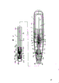
Fig. 1 is the vertical cross-section diagram of the fire rod in one embodiment of the present of invention;
Fig. 2 is the horizontal sectional view of the fire rod among the embodiment shown in Fig. 1;
Fig. 3 is the enlarged drawing of a part among Fig. 1;
Fig. 4 is the amplification part perspective view of insulated conductor among the present invention;
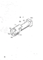
Fig. 5 is the enlarged perspective of nozzle cover of the present invention;
Fig. 6 is the decomposition section of the main part and the barred body part of fire rod of the present invention;
Fig. 7 is the partial cross section side view of the seat stand formula gas lighter in the another embodiment of the present invention;
Fig. 8 is the enlarged perspective of the fire rod in the another embodiment of the present invention, and wherein tube-like piece is by removal.
A kind of ignition device of getting the fire rod form in one embodiment of the present of invention is described in down with reference to Fig. 1 to 5.
This fire rod 1 is made up of main part 2 and barred body part 3, and this barred body part 3 is stretched by this main part 2.In this specific embodiments, as being shown among Fig. 6, this main part 2 and this barred body part 3 are taked the form of separate unit, and those unit can be combined into a fire rod in this specific embodiments.
Promptly engage with the fore-end of this nozzle member 10 in order to breakdown nozzle member 10 meaning in order to an end of the lever 14 of pushing ahead this nozzle member 10.Sealing filling member 15 is installed on the nozzle member 10 that is positioned at before this lever 14 sharp-tongued.The other end of this lever 14 is connected on the piezoelectric unit 20 of hereinafter narration.
The described lever 18 that ignites can be slidably mounted on the opening 6a place of middle case 6 forward or backward.This piezoelectric unit 20 is provided between the loam cake 7b of this ignite lever 18 and this gas storage 7.This piezoelectric unit 20 is in order to providing discharge voltage, and when lever 18 that this is ignited pulls back, and slipper 20a moves backward and causes protrusions 20b to engage with this lever 14 and with it rotation, thereby the discharge voltage by piezoelectric unit 20 generations is provided.
That is to say that this lever 14 is L-shaped and be supported in a pivot 14a and go up so that rotate around this pivot.When the protrusions 20b of the described the other end of this lever response slipper 20a moves and when upwards rotating, these lever 14 described ends draw nozzle member 10 forward with breakdown gas service duct backward.The usefulness of an electrode extremity piece of this protrusions 20b double as discharge voltage also is connected electrically on the nozzle member 10 by lever 14, and this lever 14 is made by electroconductive resin.
Another electrode extremity piece of the sliding part 20a double as discharge voltage of this piezoelectric unit 20 also is connected electrically to contactor 21a by ground strip 21.This contactor 21a is arranged in the side of a pipe fitting clamper 17 pars intermedia branches of narration hereinafter.That is to say that this ground strip 21 is to be clamped in piezoelectric unit 20 and ignite between the lever 18 in its bottom, to front curve, the flange portion 17d at close this pipe fitting clamper 17 curves crank-like then on lever 18.The front end of this ground strip 21 is arranged on the direction of central axis of this pipe fitting clamper 17 and presses against on this pipe fitting clamper 17.This ground strip 21 responds the slip of these levers 18 that ignite and moves.
This barred body part 3 is made up of tubular metal spare 25 and gas injection nozzle 26, and this nozzle 26 is installed within the leading section of this tube-like piece 25.This gas injection nozzle 26 have on its leading section nozzle sharp-tongued 27 and in its back-end portion's place's cover fit on the leading section of tracheae 28.Nozzle cover 30 is installed on the gas injection nozzle 26 so that this nozzle 26 is centered on.This nozzle cover 30 is by making such as the insulating materials of plastics etc. and having clamper part 29, and these clamper part 29 covers fit on the fore-end of this gas injection nozzle 26 and this tracheae 28.This clamper part 29 has an outside open rear end part 29a, and its cross sectional shape of this rear end part 29a is square and becomes to contact with the inner surface of this tube-like piece 25 with this tube-like piece 25 positioned coaxial.
This nozzle cover 30 provides again in addition with cover 31, and this cover 31 is connected to the top of this clamper part 29 and is stretched forward by this clamper part 29.The fore-end of this gas injection nozzle 26 is from this clamper part 29 projection forward, this cover 31 from the fore-end certain distance of this gas injection nozzle 26 round the fore-end of this gas injection nozzle 26 except that the low lower part of this gas injection nozzle 26.That is to say that the low limit of this gas injection nozzle is exposed.As Fig. 5 was clearly shown that, this Fig. 5 was the enlarged perspective of this nozzle cover 30, these cover 31 tools one front wall section 31a, and this front wall section 31a is inwardly stretching at a distance of the position of a segment distance forward by sharp-tongued of this nozzle sharp-tongued 27.Forming V-arrangement opening 31b, this opening 31b is from upwards opening with the part that this nozzle sharp-tongued 27 aligns haply with this front wall section 31a cutting.In addition, this opening 31b stretches with the form of slot shape downwards, thereby this front wall section is divided into two.Engage at the two offsides formation pair of engaging groove 31c of this cover 31 and with tube-like piece 25 aduncate fastener 25d.
This tube-like piece 25 has a front bulkhead and a flame jet 25a, and 25a outwards sprays flame by this flame jet, and this flame jet 25a is formed on the middle body of this front bulkhead.Flame jet 25a back in tube-like piece 25 forms an air suction inlet 25b.In addition, an end of tube-like piece 25 curves inwardly to form a sparking electrode 32 at this air suction inlet 25b rear.The part that this tube-like piece 25 forms sparking electrode 32 forms another air suction inlet 25b.In addition, also form four elongated air suction inlet 25c at this tube-like piece 25, this elongated air suction inlet 25c extends on the longitudinally of this tube-like piece 25, its position with the clamper part 29 opposed part places of this nozzle cover 30.
This nozzle cover 30 is contained within the tube-like piece 25, makes sparking electrode 32 be positioned on the V-arrangement opening 31b of this nozzle cover 30.Import the air of these tube-like piece 25 inside by this air suction inlet 25c that forms around the clamper part 29 of nozzle cover 30, the fore-end of the opening that forms by the lower surface at this cover 31 and this gas injection nozzle 26 of exposing by this cover 31 flows in the space of cover 31.
To this gas injection nozzle 26, and this tracheae 28 is by solid material manufacturing in order to the guiding combustion gas for the fore-end of tracheae 28 of clamper part 29 that inserts this nozzle cover 30.Tracheae 28 stretches by this tube-like piece 25 along the central axis of tube-like piece 25, and end parts projects into outside this tube-like piece 25 backward after the tracheae 28.The fore-end cover of this pipe fitting clamper 17 fits over the rear end part of this tube-like piece 25, and the rear end part cover of tracheae 28 fits over the fore-end of this pipe fitting clamper 17.
One insulated conductor 33 with insulating barrier 33a coaxially stretches by this tracheae 28 with this tracheae 28.The footpath is slightly smaller than the internal diameter of this tracheae 28 outside this insulated conductor 33, thereby forms the gas passage with little effective cross-sectional area between the inner surface of the outer surface of this insulated conductor 33 and this tracheae 28.On the insulating barrier 33a of this insulated conductor 33, form groove 33b, this groove 33b as among Fig. 4 clearly shown in, stretch along the longitudinally of this insulating barrier 33a.Part is forgone insulating barrier 33a in the front-end and back-end of this insulated conductor 33, so the heart yearn of this insulated conductor 33 all reveals naked in this front-end and back-end part.
Rear end part at this tracheae 28 is installed with hollow edged electrode extremity piece 34.That is to say that the fore-end of this electrode extremity piece 34 fits in the rear end part of this tracheae 28 by the rearward end cover of this pipe fitting clamper 17, and the rear end part of electrode extremity piece 34 outwards opens and overlap in the rearward end that fits over this pipe fitting clamper 17.The rear end part that this insulated conductor 33 reveals naked heart yearn is connected to electrode extremity piece 34 and fore-end that this insulated conductor 33 reveals naked heart yearn is connected to this gas injection nozzle 26, thereby this electrode extremity piece 34 and gas injection nozzle 26 are electrically coupled together by this insulated conductor 33.
Barred body part 3 is connected on the main part 2 in the following manner.That is to say, the pipe fitting clamper 17 that has assembled tracheae 28 and tube-like piece 25 within it is placed on one of the two halves of the middle case 6 of main part 2, make the endless groove 17b of this pipe fitting clamper 17 engage with the fastener part 6c of this middle case 6, then another half part with this middle case 6 is assembled together with above-mentioned half part.
Under assembled state, this electrode extremity piece 34 links to each other with this nozzle member 10 then, and the gas passage in the tracheae 28 is communicated with each other with gas passage in this valve system 8.In addition, the contactor 21a of ground strip 21 contacts with the outer surface of this tube-like piece 25, and sparking electrode 32 is electrically connected mutually with this piezoelectric unit 20.This gas injection nozzle 26 is electrically connected with this piezoelectric unit 20 by this nozzle member 10, this electrode extremity piece 34 and this insulated conductor 33.Because the discharge voltage that piezoelectric unit 20 produces is high alternating voltage, this discharge voltage can be applied on this nozzle sharp-tongued 27, even having narrow slightly slot also still this discharge voltage can be executed on this nozzle sharp-tongued 27 between this nozzle member 10 and this electrode extremity piece 34 or between the naked rear end part of dew of this electrode extremity piece 34 and this insulated conductor 33.
The operation principle of the fire rod 1 of this embodiment will be described in the following paragraph of this paper.When the lever 18 that will ignite pulled back, the nozzle member 10 of this valve system 8 moved forward, just discharging from gas storage 7 of fuel as mentioned above.By the combustion gas of this gas storage 7 dischargings by making the space that becomes narrow in this tracheae 28 and eject from the nozzle of this gas injection nozzle 26 sharp-tongued 27 because in this tracheae 28, inserted this insulated conductor 33.It is unimpeded with the gas passage that guarantees to lead to this gas injection nozzle 26 to form groove 33b on the outer surface of insulated conductor 33, even also still guarantee the smooth road of this gas passage when the front end face of this insulated conductor 33 insulating barrier 33a of mobile and this insulated conductor 33 in this tracheae 28 or rear end face contact with this gas injection nozzle 26 or this electrode extremity piece.
Because the gas passage in this tracheae 28 has become narrow as mentioned above, the gas flow rate that flows through this passage just can be very high, and therefore, this combustion gas can arrive sharp-tongued 27 places of this nozzle in a short period of time after breakdown valve system 8.
In addition, respond the action of this lever 18 that ignites, this piezoelectric unit 20 just produces alternating voltage, and this voltage is applied between the sparking electrode 32 and nozzle sharp-tongued 27 in the barred body part 3, thereby will light from the combustion gas of this nozzle sharp-tongued 27.
Combustion gas can be stablized and is fed to this gas injection nozzle 26 in time, this be attributed to gas passage with this tracheae 28 become narrow due to, because mix in cover 31 pressurizes and with the air that imports by air suction inlet 25c from a part of combustion gas of nozzle sharp-tongued 27, the spark that the combustion gas that ejects from this nozzle sharp-tongued 27 just can be produced owing to discharge voltage ignites fully.In addition, because this insulated conductor 33 is inserted in the tracheae 28 of the central authorities that are arranged in tube-like piece 25, this tube-like piece 25 forms earth connection, distance between this earth connection and this lead 33 just can farthest increase, make the stray capacitance of high alternating voltage discharge reduce to minimum of a value, thereby minimizing voltage is sewed and is increased discharge energy, has therefore improved the performance of igniting of this fire rod 1.
Nozzle sharp-tongued 27 is arranged within the cover 31 of this nozzle cover 30, and covers with nozzle cover 30 and tube-like piece 25.Therefore, some wind, oil, fireworks etc. that can act directly on this nozzle sharp-tongued 27 all can not make the flame outburst, and this nozzle sharp-tongued 27 and gas injection nozzle 26 can be avoided can be attached to the invasion of the foreign matter on this nozzle sharp-tongued 27 and the gas injection nozzle 26, thereby avoids weakening discharge spark.
In the above-described embodiments, though this main part 2 and barred body part 3 are independently made and be assembled together thereafter, also can integrally make one.In addition, tracheae 28 can be made by the flexible material of tool, though be preferential selection to adopt solid material.
Fig. 7 illustrates another embodiment that gets a kind of seat stand formula gas lighter form of the present invention.The seat stand formula gas lighter of this embodiment is substantially the same with the fire rod described in the previous embodiment, and therefore, identical parts all indicate with identical label.
In the seat stand formula gas lighter of this embodiment, the housing parts 55 of main part 52 is holding valve system 8 etc., and this housing parts 55 is designed to make igniter 50 to erect.The shape of gas storage 7 is made with the shape of this housing parts 55 and is consistent.Be provided at that the levers 54 that ignite in order to excitation piezoelectric unit 20 can move up and down in the main part 52, responding the pressing action to this lever that ignites, this valve system 8 is breakdown and piezoelectric unit 20 just is energized and produce discharge voltage just.In addition, this lever 54 that ignites also forms the top of shell 55.
Though it is shorter than the appropriate section in the previous embodiment with tracheae 28 that barred body part 53 is a tube-like piece 25, and though gas injection nozzle 26, nozzle cover 30, insulated conductor 33 etc. basically with previous embodiment in appropriate section substantially the same on shape or function.
Fig. 8 illustrates the fore-end of the barred body part 3 of the fire rod in an alternative embodiment of the invention, and wherein tube-like piece is by removal.Nozzle cover 30 shown in Fig. 8 ' by a clamper part 29 ' and cover 31 ' form, these two parts are made independently of one another, and to be integrated situation inequality with these two parts shown in Fig. 5.Shape of this clamper part 29 ' in a tubular form and cover fit in the fore-end of the fore-end of this tracheae 28 and this gas injection nozzle 26, and the fore-end of this gas injection nozzle by this clamper part 29 ' leading section projection forward.Provide with a flange portion 29a ' on the outer surface of the part of this clamper part 29 ' in its back-end, and this flange portion 29a ' contacts with the inner surface of unshowned tube-like piece 25 among Fig. 8.
This cover 31 ', its shape and cover similar to block fit over this clamper part 29 ' leading section so that around the fore-end of this gas injection nozzle 27 and sharp-tongued 27 projections forward of this nozzle.One of this cover 31 ' have is from the sharp-tongued front end surface 31d ' to last segment distance place of this nozzle, the part of this front end surface 31d ' is cut to form a V-arrangement opening 31a ', and this opening 31a ' is by upwards opening in the preceding part of this nozzle sharp-tongued 27.This cover 31 ' also provide with a pair of part 31b ' that cuts, should to cut part 31b ' by this cover 31 ' the opposed edge of rear end surface stretch the leading section that exceeds this clamper 29 ' part forward, thereby this cover 31 ' opposed edge on form pair of openings.When this nozzle cover 30 ' be inserted in the tube-like piece 25 shown in Fig. 1, the air that imports by air inlet port 25c by by cut opening that part 31b ' forms flow into a space 31c ' interior and with combustion gas mixing by sharp-tongued 27 injections of this nozzle, thereby improved the combustibility of combustion gas.
This fire rod among this embodiment of the present invention is being similar to fire rod among the embodiment shown in Fig. 1 aspect other parts.In addition in an embodiment of the present invention, this nozzle cover 30 ' can prevent wind, oil, fireworks etc. make the flame outburst.
Claims (5)
1, a kind of ignition device comprises: one in order to store the gas storage of combustion gas therein; Control is from the valve system of the gas supply of this gas storage; A piezoelectric unit; A gas injection nozzle that is provided on the bar-like portion of going out sharp-tongued by this valve system projection; With a sparking electrode, this electrode is arranged near this gas injection nozzle and produces discharge spark to ignite from the combustion gas of this nozzle discharge, it is characterized in that, the improvement of described ignition device comprises: a nozzle cover of making by non-conducting material, this nozzle cover be provided at this gas injection nozzle around; This nozzle cover has a front end surface that is arranged on this nozzle the place ahead from the one section distance, and this front end surface is opposite to a part of this gas injection nozzle and is opposite to one of this sparking electrode part place at it and is cut so that form an opening.
2, ignition device as claimed in claim 1 is characterized in that, this nozzle cover has a clamper part, and this clamper partly overlaps to be allocated in this gas injection nozzle; Also have a cover, this cover is stretched forward by this clamper part and exceeds the sharp-tongued of this gas injection nozzle, and this front end surface is provided on the leading section of this cover.
3, ignition device as claimed in claim 2, it is characterized in that, the cover of this nozzle cover has near the opening of a part this gas injection nozzle sharp-tongued, makes air to import in the space between this front end surface and this gas injection nozzle sharp-tongued by this opening.
4, ignition device as claimed in claim 3, it is characterized in that the diameter of the diameter of this cap greater than this clamper part, and contact with the inner surface of a tube-like piece, so that roughly the central authorities at this tube-like piece support this gas injection nozzle, this clamper part then is supported on the inner surface place away from this tube-like piece.
5, ignition device as claimed in claim 4 is characterized in that, this tube-like piece provides with an air inlet port in a part of the clamper part that is opposite to this nozzle cover.
Applications Claiming Priority (10)
| Application Number | Priority Date | Filing Date | Title |
|---|---|---|---|
| JP1990130577U JP2536865Y2 (en) | 1990-11-30 | 1990-11-30 | Ignition rod |
| JP13057890 | 1990-11-30 | ||
| JP13057990 | 1990-11-30 | ||
| JP130577/90 | 1990-11-30 | ||
| JP130578/90 | 1990-11-30 | ||
| JP130579/90 | 1990-11-30 | ||
| JP96547/91 | 1991-11-25 | ||
| JP96548/91 | 1991-11-25 | ||
| JP1991096547U JP2573994Y2 (en) | 1990-11-30 | 1991-11-25 | Ignition device |
| JP1991096548U JP2573995Y2 (en) | 1990-11-30 | 1991-11-25 | Ignition device |
Publications (2)
| Publication Number | Publication Date |
|---|---|
| CN1062030A true CN1062030A (en) | 1992-06-17 |
| CN1043077C CN1043077C (en) | 1999-04-21 |
Family
ID=27525798
Family Applications (3)
| Application Number | Title | Priority Date | Filing Date |
|---|---|---|---|
| CN91111270A Expired - Fee Related CN1044153C (en) | 1990-11-30 | 1991-11-29 | Igniting device |
| CN91111269A Expired - Lifetime CN1043077C (en) | 1990-11-30 | 1991-11-29 | Igniting device |
| CN91111268A Expired - Fee Related CN1043076C (en) | 1990-11-30 | 1991-11-29 | Igniting device |
Family Applications Before (1)
| Application Number | Title | Priority Date | Filing Date |
|---|---|---|---|
| CN91111270A Expired - Fee Related CN1044153C (en) | 1990-11-30 | 1991-11-29 | Igniting device |
Family Applications After (1)
| Application Number | Title | Priority Date | Filing Date |
|---|---|---|---|
| CN91111268A Expired - Fee Related CN1043076C (en) | 1990-11-30 | 1991-11-29 | Igniting device |
Country Status (9)
| Country | Link |
|---|---|
| US (3) | US5284439A (en) |
| EP (3) | EP0515694B1 (en) |
| CN (3) | CN1044153C (en) |
| CA (3) | CA2073977C (en) |
| DE (3) | DE69114272T2 (en) |
| ES (3) | ES2078554T3 (en) |
| HK (1) | HK1007344A1 (en) |
| MX (1) | MX174397B (en) |
| WO (3) | WO1992009852A1 (en) |
Families Citing this family (65)
| Publication number | Priority date | Publication date | Assignee | Title |
|---|---|---|---|---|
| US5509722A (en) * | 1994-04-15 | 1996-04-23 | Burns Aerospace Corporation | Convertible passenger seat assembly and grouping of passenger seat assemblies |
| US5697775A (en) * | 1994-08-18 | 1997-12-16 | Tokai Corporation | Safety device in lighting rods |
| US5897308A (en) * | 1994-08-18 | 1999-04-27 | Tokai Corporation | Safety device in lighting rods |
| USD377736S (en) * | 1995-12-07 | 1997-02-04 | Scripto-Tokai Corporation | Utility lighter |
| USD379415S (en) * | 1996-02-16 | 1997-05-27 | U.S. Catalytic Corporation | Igniting apparatus |
| USD382442S (en) * | 1996-04-23 | 1997-08-19 | Bic Corporation | Utility lighter |
| USD386045S (en) * | 1996-04-23 | 1997-11-11 | Bic Corporation | Utility lighter |
| USD383357S (en) * | 1996-04-23 | 1997-09-09 | Bic Corporation | Utility lighter |
| USD415389S (en) | 1996-04-23 | 1999-10-19 | Bic Corporation | Utility lighter |
| USD382444S (en) * | 1996-04-23 | 1997-08-19 | Bic Corporation | Utility lighter |
| USD382441S (en) * | 1996-04-23 | 1997-08-19 | Bic Corporation | Foldable utility lighter |
| USD393396S (en) | 1996-08-05 | 1998-04-14 | Bic Corporation | Utility lighter |
| USD390749S (en) | 1996-08-05 | 1998-02-17 | BIC Coproration | Utility lighter |
| USD392154S (en) | 1996-08-05 | 1998-03-17 | Bic Corporation | Utility lighter |
| TW313028U (en) * | 1996-12-23 | 1997-08-11 | Huai-Tung Li | Constantly burning heating mechanism of fuel gas soldering gun |
| US6332771B1 (en) | 1997-01-22 | 2001-12-25 | Bic Corporation | Utility lighter |
| US6065958A (en) * | 1997-01-22 | 2000-05-23 | Bic Corporation | Utility lighter |
| BR9815181A (en) * | 1997-01-22 | 2000-10-10 | Bic Corp | Utility lighter |
| US6527546B1 (en) | 1997-01-22 | 2003-03-04 | Bic Corporation | Utility lighter |
| US5934895A (en) * | 1997-01-22 | 1999-08-10 | Bic Corporation | Utility lighter |
| USD389699S (en) | 1997-03-25 | 1998-01-27 | Huang-Hsi Hsu | Igniter |
| US5967768A (en) * | 1997-08-22 | 1999-10-19 | Tokai Corporation | Lighting device |
| US5980242A (en) * | 1997-09-25 | 1999-11-09 | Man; Aman Chung Kai | Child resistant barbecue and fireplace lighter |
| USD406010S (en) * | 1998-04-08 | 1999-02-23 | Bic Corporation | Utility lighter |
| USD410363S (en) * | 1998-04-08 | 1999-06-01 | Bic Corporation | Utility lighter |
| US6468070B1 (en) | 1998-05-20 | 2002-10-22 | Calico Brands, Inc. | Multi-purpose gas lighter with ignition-resistant function |
| US20040053179A1 (en) * | 1998-08-05 | 2004-03-18 | Swedish Match Lighters B.V. | Gas lighting rods |
| USD424372S (en) * | 1998-09-18 | 2000-05-09 | Bic Corporation | Utility lighter |
| USD431157S (en) * | 1999-01-15 | 2000-09-26 | Bic Corporation | Utility lighter trigger area |
| USD435397S (en) * | 1999-03-12 | 2000-12-26 | Kil Yong Sung | Barbeque/utility lighter |
| US6325617B1 (en) | 1999-03-26 | 2001-12-04 | Calico Brands, Inc. | Child-resistant utility lighter incorporating a cam mechanism and a lever spring lock |
| CA2332994C (en) | 1999-03-26 | 2009-01-06 | Calico Brands, Inc. | Child-resistant utility lighter |
| US6050811A (en) | 1999-05-21 | 2000-04-18 | Duraflame, Inc. | Igniter |
| USD442433S1 (en) | 2000-01-24 | 2001-05-22 | Bic Corporation | Utility lighter |
| JP4317308B2 (en) * | 2000-02-03 | 2009-08-19 | 株式会社東海 | Ignition rod |
| US6428309B1 (en) * | 2000-02-22 | 2002-08-06 | Bic Corporation | Utility lighter |
| US6390809B1 (en) | 2000-04-10 | 2002-05-21 | Joseph L. Gerace | Child resistant self igniting hand held lighter |
| JP3732390B2 (en) * | 2000-06-19 | 2006-01-05 | 株式会社東海 | Ignition device |
| US6217313B1 (en) * | 2000-07-24 | 2001-04-17 | Ying Wen Luo | Childproof barbecue lighter |
| US6916171B2 (en) * | 2000-11-03 | 2005-07-12 | Bic Corporation | Multi-mode lighter |
| US7311518B2 (en) * | 2000-11-03 | 2007-12-25 | Bic Corporation | Multi-mode lighter |
| CN2483622Y (en) | 2001-04-16 | 2002-03-27 | 张巨登 | Ignition gun with safety device |
| USD467120S1 (en) | 2001-06-08 | 2002-12-17 | Chih-Hsin Yu | Igniter |
| ATE529704T1 (en) | 2001-07-27 | 2011-11-15 | Zippo Mfg Co | ALL-PURPOSE LIGHTER |
| JP2003120929A (en) * | 2001-10-11 | 2003-04-23 | Tokai Corp | Ignitor |
| US7001175B2 (en) * | 2002-01-03 | 2006-02-21 | John Jiin Chung Yang | Utility lighter with safety arrangement |
| US6840759B2 (en) | 2002-01-04 | 2005-01-11 | Ronson Corporation | Igniter incorporating a safety locking device |
| USD466370S1 (en) | 2002-04-04 | 2002-12-03 | Jin Ki Kim | Multi-purpose lighter |
| USD480266S1 (en) | 2002-05-07 | 2003-10-07 | Jin Ki Kim | Multi-purpose lighter |
| USD472765S1 (en) | 2002-06-05 | 2003-04-08 | Diamond Brands Incorporated | Multi-purpose lighter |
| DE20210536U1 (en) * | 2002-07-08 | 2002-12-19 | Unger, Stefan, 53359 Rheinbach | Hookah with electric lighter |
| US6666679B1 (en) * | 2002-12-06 | 2003-12-23 | Easton Enterprises, Inc. | Utility lighter with an improved child safety device |
| USD482932S1 (en) | 2003-06-04 | 2003-12-02 | Polycity Enterprise Limited | Lighter |
| US7967601B2 (en) * | 2006-05-30 | 2011-06-28 | Irwin Industrial Tool Company | Safety mechanism for a torch |
| US7771191B2 (en) * | 2006-05-31 | 2010-08-10 | Irwin Industrial Tool Company | Safety mechanism for a torch |
| US7563094B2 (en) * | 2007-01-12 | 2009-07-21 | John Yang | Utility lighter |
| CN100578089C (en) * | 2007-06-29 | 2010-01-06 | 宁波新海电气股份有限公司 | Pointer gun with safety mechanism |
| US8653942B2 (en) | 2008-08-20 | 2014-02-18 | John Gibson Enterprises, Inc. | Portable biometric lighter |
| CN201277587Y (en) * | 2008-09-28 | 2009-07-22 | 宁波新海电气股份有限公司 | Security igniting gun with movable press button |
| FR2945853B1 (en) * | 2009-05-25 | 2013-02-15 | Guilbert Express Sa | HAND TOOL WITH INCORPORATED BURNER AND DETACHABLE PIEZOELECTRIC IGNITION ASSEMBLY. |
| CN107013938B (en) * | 2017-05-12 | 2019-08-30 | 赣州市卫诚火机制造有限公司 | Burning torch with hard ventilation conduct piece |
| US10502419B2 (en) | 2017-09-12 | 2019-12-10 | John Gibson Enterprises, Inc. | Portable biometric lighter |
| CN109611885B (en) * | 2018-12-01 | 2021-10-01 | 邵东弘邦电子有限公司 | Ignition device |
| CN113287567A (en) * | 2021-05-26 | 2021-08-24 | 佘金浩 | Novel oxygenation device for aquatic animal breeding box |
| NL2038051B1 (en) * | 2024-06-25 | 2026-01-15 | Swedish Match Lighters Bv | A method of manufacturing a gas lighter with an extended wand and a gas lighter manufactured according to this method |
Family Cites Families (28)
| Publication number | Priority date | Publication date | Assignee | Title |
|---|---|---|---|---|
| US2888066A (en) * | 1952-03-10 | 1959-05-26 | Edward D Wilson | Electrical ignition gas torch |
| US3071182A (en) * | 1960-02-03 | 1963-01-01 | Arthur G Steinmetz | Compact fuel burner with electric ignition means |
| US3155140A (en) * | 1961-01-24 | 1964-11-03 | Edward D Wilson | Electrically ignited gas torch |
| US3431058A (en) * | 1962-03-30 | 1969-03-04 | Clevite Corp | Piezoelectrically ignited gas torch |
| FR1592091A (en) * | 1968-02-27 | 1970-05-11 | ||
| DE1905000A1 (en) * | 1969-02-01 | 1970-10-08 | Junkers & Co | Hand operated gas lighter |
| US3694134A (en) * | 1970-09-18 | 1972-09-26 | Harris Calorific Co | Electrically ignited gas torch with shut-off valve and latch therefor |
| US3947731A (en) * | 1974-01-01 | 1976-03-30 | Manufactura de Articulos para el Hogar "Aurora" Sociedad Anonima Industrial Comercial, Inmobiliaria y Financiera | Piezoelectric lighter |
| JPS5672062U (en) * | 1979-11-02 | 1981-06-13 | ||
| JPS5672063U (en) * | 1979-11-02 | 1981-06-13 | ||
| JPS5672063A (en) * | 1979-11-16 | 1981-06-16 | Toyo Ink Mfg Co Ltd | Aqueous printing ink for plastic |
| DE3374651D1 (en) * | 1982-07-22 | 1988-01-07 | Prince Industrial Dev | Catalyst combustion curling device |
| JPS6055877U (en) * | 1983-09-26 | 1985-04-19 | 株式会社タニタ | fire starter crater |
| DE3427587A1 (en) * | 1984-07-26 | 1986-02-06 | Leybold-Heraeus GmbH, 5000 Köln | SPRAYING DEVICE FOR CATODE SPRAYING SYSTEMS |
| JPH0220620Y2 (en) * | 1984-11-05 | 1990-06-05 | ||
| DE8436764U1 (en) * | 1984-12-15 | 1985-03-14 | Consuma AG, Balzers | HAND GAS LIGHTER |
| JPS61272518A (en) * | 1985-05-25 | 1986-12-02 | Nakajima Doukoushiyo:Kk | Thermal machining apparatus using liquid gas |
| JPS6245560A (en) * | 1985-08-22 | 1987-02-27 | Sanyo Kokusaku Pulp Co Ltd | Novel acrylate and production thereof |
| JPH037725Y2 (en) * | 1985-09-07 | 1991-02-26 | ||
| JPS6281858U (en) * | 1985-11-12 | 1987-05-25 | ||
| JPS6330049A (en) * | 1986-07-23 | 1988-02-08 | Hitachi Ltd | MSK demodulation circuit |
| JPS6349167A (en) * | 1986-08-15 | 1988-03-01 | 日本金属株式会社 | Oxygen supply container |
| JPH0547951Y2 (en) * | 1986-09-11 | 1993-12-17 | ||
| JPH0424300Y2 (en) * | 1986-09-12 | 1992-06-08 | ||
| US4920952A (en) * | 1987-08-05 | 1990-05-01 | Masahiko Nakajima | Heat processing apparatus using liquified gas |
| US4881894A (en) * | 1988-02-16 | 1989-11-21 | Cooper Industries, Inc. | Self-igniting portable torch assembly |
| US4892475A (en) * | 1988-12-08 | 1990-01-09 | Union Carbide Corporation | Ignition system and method for post-mixed burner |
| ES2020868A6 (en) * | 1990-02-28 | 1991-10-01 | Flamagas | Liquefied gas kitchen lighter. |
-
1991
- 1991-11-29 ES ES91920813T patent/ES2078554T3/en not_active Expired - Lifetime
- 1991-11-29 CA CA002073977A patent/CA2073977C/en not_active Expired - Fee Related
- 1991-11-29 MX MX9102306A patent/MX174397B/en unknown
- 1991-11-29 WO PCT/JP1991/001666 patent/WO1992009852A1/en not_active Ceased
- 1991-11-29 CA CA002073961A patent/CA2073961C/en not_active Expired - Fee Related
- 1991-11-29 CN CN91111270A patent/CN1044153C/en not_active Expired - Fee Related
- 1991-11-29 EP EP91920814A patent/EP0515694B1/en not_active Expired - Lifetime
- 1991-11-29 DE DE69114272T patent/DE69114272T2/en not_active Expired - Fee Related
- 1991-11-29 US US07/910,163 patent/US5284439A/en not_active Expired - Fee Related
- 1991-11-29 HK HK98106580A patent/HK1007344A1/en not_active IP Right Cessation
- 1991-11-29 CN CN91111269A patent/CN1043077C/en not_active Expired - Lifetime
- 1991-11-29 ES ES91920769T patent/ES2082997T3/en not_active Expired - Lifetime
- 1991-11-29 WO PCT/JP1991/001667 patent/WO1992009853A1/en not_active Ceased
- 1991-11-29 DE DE69116868T patent/DE69116868T2/en not_active Expired - Fee Related
- 1991-11-29 US US07/910,165 patent/US5322433A/en not_active Expired - Fee Related
- 1991-11-29 DE DE69114273T patent/DE69114273T2/en not_active Expired - Fee Related
- 1991-11-29 US US07/910,164 patent/US5326256A/en not_active Expired - Fee Related
- 1991-11-29 CN CN91111268A patent/CN1043076C/en not_active Expired - Fee Related
- 1991-11-29 WO PCT/JP1991/001665 patent/WO1992009851A1/en not_active Ceased
- 1991-11-29 ES ES91920814T patent/ES2078555T3/en not_active Expired - Lifetime
- 1991-11-29 CA CA002073980A patent/CA2073980C/en not_active Expired - Fee Related
- 1991-11-29 EP EP91920813A patent/EP0515693B1/en not_active Expired - Lifetime
- 1991-11-29 EP EP91920769A patent/EP0516858B1/en not_active Expired - Lifetime
Also Published As
Similar Documents
| Publication | Publication Date | Title |
|---|---|---|
| CN1043077C (en) | Igniting device | |
| HK1007344B (en) | Ignition device | |
| US4778380A (en) | Rod-shaped gas igniter | |
| CN1251161A (en) | Utility lighter | |
| EP0259745B1 (en) | Rod-shaped piezoelectric gas igniter | |
| CN1149351C (en) | The Ignition Operating Mechanism of the Piezoelectric Ignition Rod | |
| JPH06307638A (en) | Extended ignition device for piezoelectric ignition gas lighter | |
| US5178532A (en) | Electrical igniter for gas lighter | |
| CN1195956C (en) | Ignitor | |
| JPH0412360Y2 (en) | ||
| EP0660045A2 (en) | Pocket lighter | |
| JP2536865Y2 (en) | Ignition rod | |
| KR900009818Y1 (en) | A cigarette case | |
| CN2210544Y (en) | Improved cigarette case with cigarette lighting device | |
| KR890000253Y1 (en) | Windproof writer case | |
| CN103062791A (en) | Gas lighter | |
| JP3114842B2 (en) | Internal combustion gas lighter | |
| HK1007439B (en) | Ignition device | |
| JPH01314813A (en) | Ignitor | |
| JPH04108154U (en) | igniter | |
| JPH059697B2 (en) | ||
| JPH09243075A (en) | Internal combustion gas lighter | |
| JPH04108155U (en) | igniter |
Legal Events
| Date | Code | Title | Description |
|---|---|---|---|
| C10 | Entry into substantive examination | ||
| SE01 | Entry into force of request for substantive examination | ||
| C06 | Publication | ||
| PB01 | Publication | ||
| C14 | Grant of patent or utility model | ||
| GR01 | Patent grant | ||
| C15 | Extension of patent right duration from 15 to 20 years for appl. with date before 31.12.1992 and still valid on 11.12.2001 (patent law change 1993) | ||
| OR01 | Other related matters | ||
| C17 | Cessation of patent right | ||
| CX01 | Expiry of patent term |
Expiration termination date: 20111129 Granted publication date: 19990421 |