Background
The cloth is a material commonly used in decorative materials. Comprises various fabrics such as chemical fiber carpets, non-woven wallcoverings, linen, nylon fabrics, colored rubberized fabrics, flannel and the like. Cloth plays a considerable role in decorative displays, often a major non-negligible effort in the overall sales space. A large amount of cloth is used for wall surface decoration, partition and background treatment, and a good commercial space display style can be formed. Spreading and cutting the cloth without separating the cloth. In particular, the processing of square cloth, namely the cloth sewn into a square strip shape, is developed from the original pure manual work to the automatic processing widely adopted nowadays.
The process needs a perforating machine which is an industrial machine with wide application and is almost used in all industrial industries; in the textile industry, the perforating machine is also a very important textile machine, a plurality of textile products have perforating requirements, and the perforating machine in the textile industry is developed very quickly; from the development process of the punching machine, the high-efficiency line from manual punching machine, mechanical punching machine, full-automatic punching machine, automatic positioning punching machine and super full-automatic punching machine from manual to automatic is experienced. In China, many large-scale and ultra-large-scale textile enterprises have very advanced automatic punching machines, but still a great number of small and miniature textile enterprises use the traditional manual or mechanical punching machines.
Chinese patent CN201510038366.2 discloses a thermal punching mechanism of an automatic cutting bed, which comprises a heating device, a pressure plate, a punching needle, a motor, a guide device, a support plate, an air cylinder, a connecting plate and an air cylinder fixing plate; the cylinder body of the air cylinder is fixed with a frame of the automatic cutting bed through an air cylinder fixing plate, and the connecting plate is fixed with a piston rod of the air cylinder; the motor is fixed with the connecting plate, the backup pad is fixed in the bottom of the piston rod of cylinder, and guider is connected with the backup pad, and heating device is fixed with guider's lower extreme, and the upper end of perforating needle is connected with the power take off of motor, and the hole of backup pad is passed and is located heating device's heating hole to perforating needle's lower extreme, and the clamp plate is fixed in heating device's below. According to the invention, the perforating needle is used for perforating at a high temperature through the heating device, and the fabric around the drilled hole is directly ironed, so that after the perforating needle is taken out of the fabric, the edge cutting opening on the fabric is flat and cannot deform after the drilled hole is cooled, and the drilled hole on the special fabric with high elasticity is easy to identify.
However, when the cloth of other side bar form punches, foretell automatic cutting bed's hot mechanism of punching needs artifical manual to adjust, and artifical manual regulation can be played comparatively even hole, but artifical manual regulation has the error, leads to the hole interval to have the difference, and artifical manual regulation efficiency of punching is slow moreover, because the return motion of the huge especially drift of work load often needs manual operation to reply, causes staff fatigue easily, influences and cuts efficiency.
Disclosure of Invention
The invention aims to provide a square cloth belt punching device to solve the technical problems that when cloth is uniformly punched, efficiency is low, and the edge of a punched hole is rough due to the fact that a material to be processed cannot be effectively pressed.
In order to achieve the purpose, the invention provides a square cloth tape punching device, which comprises: the sliding device comprises a base, a sliding groove is formed in the right side of the base, a movable plate is arranged above the base, a sliding block is arranged at the lower end of the movable plate, and the sliding block is arranged in the sliding groove in a sliding mode; a vertical plate is arranged on one side of the base, a cam is rotatably arranged at the upper end of the vertical plate, a connecting rod is rotatably arranged at the lower end of the cam, the other end of the connecting rod is rotatably connected with the right end of the movable plate, an elastic plate body is arranged on the movable plate, the elastic plate body is obliquely arranged, the left end of the elastic plate body is higher in inclination, a punching rod is connected with the left end of the elastic plate body, a drill bit is connected with the lower end of the punching rod, and the lower end of the cam is in contact with the upper end of the elastic plate body; a containing groove is formed in the left side of the base, a feeding mechanism is arranged in the containing groove and comprises a material spreading device and a material pressing device, the material spreading device is connected with the elastic plate body, and the material pressing device is connected with the elastic plate body in a sliding mode; the material spreading device comprises a material spreading part and a feeding device, the material spreading part is arranged at a position corresponding to the bottom of the punching device, and the feeding device is arranged on one side of the material spreading part; the material to be processed is laid on the material spreading part, and the feeding device drives the material spreading part to enable the material to be processed to move along a set direction; the pressing device comprises a contraction rod and a pressing block, the contraction rod is connected with the pressing block, the tail end of the contraction rod is connected with the lifting cylinder, and the pressing block is used for pressing the material on the punching foam block to prevent the material to be processed from moving when the lifting cylinder moves downwards and abuts against the material to be processed.
The invention has the following beneficial effects:
the method comprises the following steps that materials to be processed are placed on a material paving device, a driving motor drives a cam to rotate, the cam drives a connecting rod to move in the rotating process, a sliding block at the lower end of a movable plate slides in a left-right reciprocating mode along a sliding groove, the movable plate moves left and right along with the movable plate, meanwhile, the cam presses down an elastic plate body in the rotating process to enable the elastic plate body to move up and down in a reciprocating mode, a punching rod connected to the left end of the elastic plate body moves up and down along with the movable plate, and when the punching rod moves down, a; simultaneously, during the elastic plate body up-and-down reciprocating motion, material feeding unit drive shop material spare so that should wait to process the material and remove along established direction to the distance of removal is certain, thereby can beat even hole, the briquetting is in thereby the lift cylinder downward motion with wait to process the material butt and establish the material pressure on the foam block that punches and prevent to wait to process the material removal, thereby the hole that makes the drill bit beat is more exquisite, the edge in hole more slick and sly. The invention has novel structural design, and can complete the punching work of the material to be processed by driving the drill bit at one end of the elastic plate body to move up and down through the rotation of the cam.
In addition to the objects, features and advantages described above, other objects, features and advantages of the present invention are also provided. The present invention will be described in further detail below with reference to the drawings.
Drawings
The accompanying drawings, which are incorporated in and constitute a part of this application, illustrate embodiments of the invention and, together with the description, serve to explain the invention and not to limit the invention. In the drawings:
FIG. 1 is a schematic structural view of a square cloth tape perforating device according to a preferred embodiment of the invention;
fig. 2 is a schematic structural view of another view angle of the square cloth tape perforating device according to the preferred embodiment of the invention;
fig. 3 is a partial structure view of a square cloth tape perforating device according to a preferred embodiment of the present invention;
fig. 4 is another view schematically illustrating a partial structure of a square cloth tape perforating device according to a preferred embodiment of the present invention;
fig. 5 is another view schematically illustrating a partial structure of a square cloth tape perforating device according to a preferred embodiment of the present invention;
fig. 6 is another view schematically illustrating a partial structure of a square cloth tape perforating device according to a preferred embodiment of the present invention;
fig. 7 is a partial structural schematic view of a pressing device according to a preferred embodiment of the present invention;
wherein, 101, a base, 102, a sliding groove, 103, a movable plate, 104, a sliding block, 105, a vertical plate, 106, a cam, 107, a connecting rod, 108, an elastic plate body, 109, a punching rod, 110, a drill bit, 111, a receiving groove, 112, a feeding mechanism, 113, a driving motor, 201, a spreading device, 202, a pressing device, 301, a spreading part, 302, a feeding device, 303, a material to be processed, 401, a receiving groove, 402, a punching foam block, 403, a drawing opening, 404, a first through groove, 405, a second through groove, 501, a notch, 502, a groove body, a first rolling shaft 601, a second rolling shaft 602, a linkage belt 603, a first gear 611, a second gear 612, 613, a third gear, 621, a first ratchet wheel, 622, a second ratchet wheel 631, a first rotation limiting block, 632, a second rotation limiting block, 640, a driving spur rack, 641, a straight tooth part, 642, a driving connecting part 701, a contraction rod, 702, a pressing block, 711. a first rod section 721 and a second rod section.
Detailed Description
Embodiments of the invention will be described in detail below with reference to the drawings, but the invention can be implemented in many different ways, which are defined and covered by the claims.
Referring to fig. 1, which is a schematic structural view of a square cloth tape perforating device according to a preferred embodiment of the present invention, the present invention provides a square cloth tape perforating device 10, the square cloth tape perforating device 10 comprises a base 101, a chute 102 is arranged at the right side of the base 101, a movable plate 103 is arranged above the base 101, a slide block 104 is arranged at the lower end of the movable plate 103, the slide block 104 is arranged in the chute 102 in a sliding way, base 101 one side is equipped with vertical board 105, vertical board 105 upper end is rotated and is equipped with a cam 106, the tip rotation is provided with a connecting rod 107 under the cam 106, the other end of connecting rod 107 rotates with the right-hand member of fly leaf 103 and links to each other, be equipped with elastic plate body 108 on the fly leaf 103, elastic plate body 108 slope sets up, elastic plate body 108's left end is the higher end of slope, elastic plate body 108's left end is connected with perforating rod 109, perforating rod 109 lower extreme is connected with drill bit 110, the lower extreme of cam 106 contacts with elastic plate body 108's upper end.
The left side of the base 101 is provided with a containing groove 111, the containing groove 111 is internally provided with a feeding mechanism 112, the upper end of the vertical plate 105 is provided with a driving motor 113, and the output end of the driving motor 113 is connected with the rotating shaft of the cam 106. The right end of the elastic plate body 108 is fixedly disposed on the movable plate 103. The right end of the movable plate 103 is provided with a mounting bracket, and one end of the connecting rod 107 is rotatably arranged on the mounting bracket. The right end of the spring plate body 108 is located on the left side of the mounting bracket.
In the invention, a material to be processed is placed on a base 101, a driving motor 113 drives a cam 106 to rotate, the cam 106 drives a connecting rod 107 to move in the rotating process, so that a sliding block 104 at the lower end of a movable plate 103 slides in a reciprocating manner from side to side along a sliding groove 102, the movable plate 103 moves from side to side, meanwhile, the cam 106 presses down an elastic plate body 108 in the rotating process, so that the elastic plate body 108 reciprocates from top to bottom, a punching rod 109 connected to the left end of the elastic plate body 108 moves from top to bottom, and when the punching rod 109 moves downwards, a drill 110 punches a material to be processed on the base.
As shown in fig. 2, for example, the feeding mechanism 112 includes a material spreading device 201 and a material pressing device 202. The spreading device 201 is connected to the elastic plate body 108, and in this embodiment, the spreading device 201 is connected to the end of the elastic plate body 108 through the driving connection portion 642 of the driving spur rack. The pressing device 202 is slidably connected to the elastic plate 108. The cloth, the cloth material, the cloth belt or other garment materials are laid on the material laying device 201, the material laying device 201 is used for driving the cloth, the garment material, the cloth belt or other garment materials to move, and therefore the punching device 104 is matched to punch uniform holes in the cloth, the garment material, the cloth belt or other garment materials to be processed 303; the pressing device 202 presses the cloth, clothing, cloth tape or other clothing material waiting for processing to make it immovable in the process of descending the punching device 104, so that the material to be processed can be stably contacted with the drill 110 of the punching device 104, thereby effectively and quickly punching holes. After punching, the pressing device 202 is also out of contact with the material to be processed as the punching device 104 is out of contact, so that the material to be processed is released and can be moved by the paving device 201 to punch again, and the paving device 201 and the pressing device 202 repeat the steps when punching again.
Referring to fig. 2 and 3 together, fig. 3 is a partial structure schematic view of a square cloth tape perforating device according to a preferred embodiment of the present invention, where the material spreading device 201 includes a material spreading member 301 and a material feeding device 302, the material spreading member 301 is disposed at a position corresponding to the bottom of the perforating device 104, and the material feeding device 302 is disposed at one side of the material spreading member 301. The material to be processed is laid on the paving member 301, and the feeding device 302 drives the paving member 301 to move the material to be processed in a predetermined direction. For example, the paver 301 as a whole takes on a cuboid shape; as another example, the paver 301 as a whole assumes an ellipsoidal shape. In this embodiment, the overall shape of the material spreading member 301 is a rectangular parallelepiped. It is understood that the shape of the material spreading member 301 is not limited to the square shape and the circular shape, and the specific production process can be designed according to the actual working requirement or according to the difference of the materials to be processed of the cloth, the clothing material, the cloth belt or other clothing materials.
Referring to fig. 4, which is another schematic view of a partial structure of a square cloth tape perforation apparatus according to a preferred embodiment of the present invention, for example, the spreading member 301 includes a receiving slot 401 and a perforated foam block 402, the receiving slot 401 is matched with the perforated foam block 402, and the perforated foam block 402 is received in the receiving slot 401. In this embodiment, the receiving groove 401 is a square groove, and the perforated foam block 402 is a square block. Preferably, a drawing opening 403 is formed in a side edge of the accommodating groove 401, and the perforated foam block 402 is fed into the accommodating groove 401 from the drawing opening 403. The shape of the pull opening 403 matches the cross-sectional shape of the perforated foam block 402. For example, the drawing opening 403 is square in shape. In this embodiment, the perforated foam block 402 is slidably fed into the receiving groove 401 from the drawing opening 403. In this embodiment, the drawing opening 403 is disposed on the opposite side of the feeding device 302, that is, the drawing opening 403 and the feeding device 302 are respectively located on the opposite sides of the accommodating groove 401.
It can be understood that the function of the perforating foam block 402 is to cooperate with the drill 110 of the perforating device 104, that is, when the drill 110 perforates the material to be processed, the drill 110 continues to travel through the material and is accommodated in the perforating foam block 402, so that the perforation can be smoothly performed. In this embodiment, the foam block 402 is made of foam material, and the foam material has certain elasticity, so that the drill 110 may have certain buffering when contacting with the material to be processed, that is, the drill 110 may contact with the material to be processed in advance, and then the drill 110 punches a hole in the material to be processed, so that the hole punched by the drill 110 is more delicate, and the edge of the hole is smoother.
In order to punch holes with different shapes, the paving member 301 comprises a containing groove 401 and a perforated foam block 402, the containing groove 401 is matched with the perforated foam block 402, and the perforated foam block 402 is contained in the containing groove 401; the perforated foam block 402 has a plurality of honeycomb holes, the plurality of honeycomb holes penetrate through the entire perforated foam block 402, and the shape of the honeycomb holes of the perforated foam corresponds to that of the drill bit. That is, the perforated foam block 402 may also be provided in the form of a plurality of cell holes, i.e., a plurality of cell holes extending through the entire perforated foam block 402. For example, the shape of the honeycomb holes formed in the perforated foam block 402 corresponds to the shape of the drill 110, i.e., the shape of the drill 110 is not limited to a circular through hole, and may have a regular pentagon shape, a triangle shape, or the like. That is, the shape of the honeycomb holes is circular, square or polygonal, and the shape of the drill bit 110 corresponds to the shape of the honeycomb holes; the punching tool is suitable for punching materials to be processed in different types and shapes, is wide in application range, is formed by attaching adjacent honeycomb holes, and is provided with a silencing layer around the containing groove 401, wherein the silencing layer is used for wrapping a plurality of honeycomb holes; the mute layer is filled with mute cotton; so as to have good sound insulation effect. For example, the length of the drill bit 110 is greater than the height of the feed mechanism 112; as another example, the outer diameter of the drill bit 110 is tangent to the inner diameter of the honeycomb hole; the punching is rapid and tidy, no redundant waste is generated, and the efficiency is high. Meanwhile, the honeycomb holes with different apertures are conveniently replaced by the punching foam block 402, so that the punching machine is suitable for punching without waiting for processing materials, and is wide in application range. Therefore, the honeycomb holes formed by the punching foam correspond to the drill bit 110, and holes in different shapes can be punched, so that different production requirements can be met.
In an embodiment, a collecting tray for receiving the cut waste material to be processed is arranged outside the accommodating groove 401, and the collecting tray corresponds to the honeycomb holes; it reduces artifical intensity of labour, improves production efficiency, satisfies large batch production and processing requirement, and the practicality is strong, and the useless material bits of treating processing that produce during the processing hole can be collected centralized processing, improves operational environment's quality, improves work efficiency.
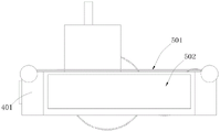
Referring to fig. 5, which is another schematic view of a partial structure of a square cloth tape perforating device according to a preferred embodiment of the present invention, in order to limit the perforated foam block 402 in the receiving slot 401, for example, the receiving slot 401 includes a slot 501 and a slot body 502, which are communicated with each other, and referring to fig. 4, the slot 501 is an opening of the receiving slot 401, the slot 501 faces the bottom of the perforating device 104, and the material to be processed is spread over the slot 501. For example, the drawing opening 403 is communicated with the slot body 502, and the slot body 502 is used for accommodating the perforated foam block 402. The length and width of the notch 501 are smaller than those of the groove body 502. Alternatively, when the paving member 301 has an overall ellipsoidal shape, the radius of each notch 501 is smaller than that of the groove body 502. In this embodiment, the length of the notch 501 is 85% to 95% of the length of the groove body 502, for example, the length of the notch 501 is 85% of the length of the groove body 502; as another example, the length of the notch 501 is 95% of the length of the channel body 502. Preferably, the length of the notch 501 is 90% of the length of the groove body 502. For example, the depth of the notch 501 is much smaller than the depth of the groove body 502, for example, the depth of the notch 501 is equal to 5% -8% of the depth of the groove body 502; for example, the depth of the notch 501 is equal to 5% of the depth of the channel body 502; for another example, the depth of the notch 501 is equal to 8% of the depth of the groove body 502, and preferably, the depth of the notch 501 is equal to 6% of the depth of the groove body 502. Thus, after the perforated foam block 402 slides into the slot body 502 through the drawing opening 403, since the overall width of the slot body 502 is greater than the overall width of the slot opening 501, the perforated foam block 402 cannot slide out of the slot opening 501, that is, the perforated foam block 402 is confined in the slot body 502, so that even when the friction coefficient between the drill bit 110 and the perforated foam block 402 is large after drilling into the perforated foam block 402, that is, when the drill bit 110 exerts a vertical upward force on the perforated foam block 402, the perforated foam block 402 is still held in the slot body 502 by the confining action of the slot opening 501, thereby restricting the movement of the perforated foam block 402; in addition, in this embodiment, the depth of the notch 501 is far smaller than the depth of the groove body 502, and meanwhile, the pressing device 202 can press down the material to be processed, so that the depth of the notch 501 does not affect the contact drilling of the drill 110 on the material to be processed.
With reference to fig. 4 and fig. 5, further, in order to limit the perforated foam block 402 in the receiving slot 401, a pull door beam 404 is disposed above the pull opening 403, that is, the pull opening 403 is formed by the pull door beam 404 and the bottom of the side edge of the receiving slot 401 enclosing together. For example, the door beam 404 is detachably connected to two ends of the side of the receiving groove 401. For example, one end of the door beam 404 is rotatably connected to one end of the side of the receiving groove 401, and the other end of the door beam 404 is engaged with the other end of the side of the receiving groove 401. Similarly, the containing groove 401 includes a notch 501 and a groove body 502 which are communicated with each other, the notch 501 is an opening of the containing groove 401, the notch 501 faces the bottom of the punching device 104, and a material to be processed is paved above the notch 501. For example, the drawing opening 403 is communicated with the slot body 502, and the slot body 502 is used for accommodating the perforated foam block 402. The length and width of the notch 501 are smaller than those of the groove body 502. In this embodiment, the slot 501 and the slot body 502 are in a convex shape, correspondingly, the perforated foam block 402 is also in a convex shape, and the perforated foam block 402 is disposed adjacent to one end of the drawing opening 403 in a concave manner, and the drawing door beam 404 is clamped in the concave position, so that when the drill bit 110 applies a vertical upward force to the perforated foam block 402, the perforated foam block 402 is still retained in the slot body 502 under the limiting action of the drawing door beam 404, thereby limiting the movement of the perforated foam block 402; moreover, since the perforated foam block 402 is in a convex shape, there is no gap between the material to be processed and the surface of the perforated foam block 402, and the material to be processed can directly contact the perforated foam block 402, so that the hole drilled by the drill 110 on the material to be processed is more delicate, the edge of the hole is smoother, and the generated impurities are less.
Referring to fig. 6, which is another view angle schematic diagram of a partial structure of a square cloth tape perforating device according to a preferred embodiment of the present invention, with reference to fig. 4, 5 and 6, for example, the feeding device 302 includes a first rolling shaft 601, a second rolling shaft 602, a linkage belt 603, a first gear 611, a second gear 612, a third gear 613, a first ratchet 621, a second ratchet 622, a first rotation limiting block 631, a second rotation limiting block 632 and a driving spur rack 640, and two side portions of the accommodating groove 401 are respectively provided with a first through groove 404 and a second through groove 405. It should be noted that the side portions of the accommodating groove 401 and the side edges of the accommodating groove 401 are in a relative vertical relationship, and both refer to edge portions of the accommodating groove 401, that is, the side portions of the accommodating groove 401 are perpendicular to the side edges of the accommodating groove 401, that is, there are two opposite side portions of the accommodating groove 401, and similarly, there are two opposite side edges of the accommodating groove 401. The first rolling shaft 601 is accommodated in the first through groove 404, and one end of the first rolling shaft 601 is rotatably connected to the accommodating groove 401, and the other end of the first rolling shaft is provided with teeth and is engaged with the first gear 611. The second rolling shaft 602 is accommodated in the second through groove 405, one end of the second rolling shaft 602 is rotatably connected to the accommodating groove 401, and the other end is connected to the first rolling shaft 601 through the linkage belt 603. In this embodiment, a third through groove is formed on a side edge of the accommodating groove 401, and the linkage belt 603 is accommodated in the third through groove. It should be noted that the third through groove and the drawing opening 403 are respectively located on two opposite sides of the accommodating groove 401.
In order to stabilize the rotation of the first rolling shaft 601 and the second rolling shaft 602, in this embodiment, the bottoms of the first through groove 404 and the second through groove 405 are semi-circular grooves, that is, the cross sections of the bottoms of the first through groove 404 and the second through groove 405 are semi-circular, the outer diameter of the first rolling shaft 601 is matched with the inner diameter of the first through groove 404, for example, the tolerance between the outer diameter of the first rolling shaft 601 and the inner diameter of the first through groove 404 is 0.02mm to 0.05 mm. Similarly, the outer diameter of the second rolling shaft 602 matches the inner diameter of the second through groove 405, for example, the tolerance between the outer diameter of the second rolling shaft 602 and the inner diameter of the second through groove 405 is 0.02mm to 0.05 mm. Preferably, lubricating oil is disposed on the surfaces of the first rolling shaft 601 and the first through groove 404, and lubricating oil is disposed on the surfaces of the second rolling shaft 602 and the second through groove 405, so that the first rolling shaft 601 and the second rolling shaft 602 can stably rotate around the first through groove 404 and the second through groove 405, respectively, and the movement of the material to be processed is smooth. The above description is only a preferred embodiment of the present invention and is not intended to limit the present invention, and various modifications and changes may be made by those skilled in the art. Any modification, equivalent replacement, or improvement made within the spirit and principle of the present invention should be included in the protection scope of the present invention.