Cooling system and motor
Technical Field
The invention relates to a cooling system for an electric machine and to an electric machine.
Background
An electric machine has a component, for example a so-called rotor, which rotates during its operation. The motor may become hot due to the components and due to the current flowing through the electrical conductors of the motor. But the motor can be cooled by a cooling system.
The publication DE 102013104711 a1 describes an electric machine having a rotor shaft and a device for cooling the rotor shaft, wherein the rotor shaft is designed as a hollow shaft. It is proposed that the cooling device has a stationary cooling lance which passes axially through the hollow shaft. The cooling lance has an inlet and an outlet for a cooling medium and a cooling channel connected to the inlet and the outlet, which cooling channel passes axially through the cooling lance.
Publication EP 0660492 a1 describes a cooling system for an electric motor having a gearbox, a liquid-cooled but hollow rotor shaft for the electric motor and an externally cooled stator. The cooling system has a shaft cooling structure that enables a high degree of utilization of the electric machine and can also be used for packaged and thus noise-reduced electric machines.
Furthermore, a rotating electrical machine is known from publication EP 1168572 a2, which has a cooled hollow rotor shaft.
Disclosure of Invention
Against this background, it is an object of the present invention to improve the cooling system of an electric machine.
This object is achieved with a cooling system and an electric machine having the features described below. Embodiments of the cooling system and of the electric machine result from the solutions and the description below.
The cooling system according to the invention is provided for cooling an electric machine having a drive shaft for driving an external device and a rotor shaft of a rotor of the electric machine. The cooling system has as components at least one first jacket and at least one second jacket, wherein the first jacket coaxially surrounds the drive shaft, wherein the second jacket coaxially surrounds the first jacket. The first and second sleeves define a first flow space for a cooling medium. Furthermore, the rotor shaft coaxially surrounds or defines a second sleeve, the second sleeve and the rotor shaft defining or surrounding a second flow space for the cooling medium. The second sleeve is designed to separate the first flow space from the second flow space of the cooling system.
A cooling system is usually provided for an electric machine having a housing, wherein the drive shaft and the rotor shaft can rotate relative to the housing. The two bushings of the cooling system are fixedly connected to the housing and are therefore fastened to the housing. In operation of the electric machine and/or the cooling system, the drive shaft rotates within the first sleeve at the rotational speed of the device to be driven and the rotor shaft rotates about the second sleeve at the rotational speed of the rotor.
It is proposed that the drive shaft, the two bushings and the rotor shaft are designed as cylinders or cylinders and have a common axis of symmetry.
In one embodiment, a first of the two flow channels can be used or is to be used as a supply line for the cooling medium, and a second of the two flow channels can be used or is to be used as a return line for the cooling medium. In operation of the cooling system, it is proposed that the cooling medium flows or is conveyed through the supply line in an axially directed first direction. The cooling medium then flows in the radial direction from the supply line to the return line or is conveyed in the radial direction. Furthermore, it is proposed that the cooling medium flows or is conveyed through the return line in a second axially directed direction, which is opposite to the first axially directed direction. In this case, a stationary liquid column of the cooling medium is obtained in one of the two directions, usually in the first direction, when the cooling medium flows in the supply line between the two stationary/fixed bushings. If the cooling medium flows in the reverse direction in the return path, the liquid column also turns due to the rotation of the rotating shaft.
The two flow regions are connected to one another by and/or via a transition region, wherein the cooling medium can flow or be conveyed in the radial direction through the transition region.
In one embodiment, the flow space designed as the return path coaxially surrounds the flow space designed as the supply path, wherein a stationary liquid column of the cooling medium is obtained in the supply path between the two stationary sleeves and a rotating liquid column is obtained in the return path between the stationary second sleeve and the rotating rotor shaft.
The electric machine according to the invention has an embodiment of the rotor shaft, the drive shaft and the cooling system.
The rotor shaft coaxially surrounds the drive shaft, wherein components of the cooling system, at least a bushing, are arranged between the drive shaft and the rotor shaft.
The rotor shaft is designed as a carrier of the rotor for rotating the rotor relative to the stator at the rotational speed of the electric machine. The drive shaft is designed to rotate at the rotational speed of the external device in order to drive the external device. In this case, the two rotational speeds differ by a rotational speed difference.
With the proposed cooling system surrounded by the rotor shaft, the rotor shaft can be cooled without cavitation.
In the case of an electric machine, the hollow rotor shaft surrounds a drive shaft of the electric machine, which may also be designed and/or referred to as a flange shaft. The rotor shaft can be cooled on an inner profile of the rotor shaft, which defines a second flow space for the cooling medium as an outer wall. The inlet on the supply line and the outlet on the return line are arranged on a first side of the electric machine and between the drive shaft and the rotor shaft, and the transition region between the supply line and the return line is arranged on a second side of the drive shaft and the rotor shaft and of the electric machine opposite the first side. The cooling medium can flow through the supply line and the return line in opposite directions in the axial direction. In this case, even at high rotational speeds of more than 5000 revolutions per minute, cooling of the rotor shaft and thus of the rotor rotating with the rotor shaft can be ensured, while the cooling medium can flow through the cooling system without air pockets.
The cooling medium flows between the two stationary or stationary and cylindrical jackets of the cooling jacket, which delimit and/or delimit a flow space, which is usually designed as a supply line, and an inlet to this flow space, which has a cross section that is as small as possible and therefore requires only a small installation space. Inside the supply line, the cooling medium constitutes an axial liquid column. In the flow region designed as the return flow path, the cooling medium is set in rotation by the rotor shaft, which defines the return flow path as the second flow region and forms the outer wall of this second flow region. A rotating liquid column is thus formed. A radial or rotating flow section of the cooling medium is thereby formed only on the inner surface of the rotor shaft.
A cooling system arranged coaxially between the drive shaft and the rotary shaft, which cooling system furthermore forms the inner space and/or the core of the rotary shaft, can thus be used for cooling measures.
The electric machine also has a stator, wherein the rotor is rotatable relative to the stator. In the generator mode of operation of the electric machine, mechanical energy is converted into electrical energy, and in the motor mode of operation, electrical energy is converted into mechanical energy.
As components of the cooling system, two stationary bushings are used between the transmission shaft or the flange shaft and the rotor shaft, wherein the two stationary bushings are arranged outside the central axis, i.e. the axis of symmetry or the axis of rotation, of the rotor shaft and the transmission shaft. The cooling lance, which is usually arranged in the axial center of the shaft, can therefore be dispensed with in comparison with the prior art.
Furthermore, the drive shaft or the flange shaft arranged inside the first sleeve is sealed by a cooling medium, for example water or oil.
In operation of the electric machine, the rotor arranged on the rotor shaft rotates at the machine speed relative to the stator. While the drive shaft arranged inside the rotor shaft and the cooling system rotates at the rotational speed of an external device to be driven by the drive shaft, such as a wheel, which may be designed as a component of a motor vehicle. The gap between the drive shaft or flange shaft and the rotor shaft is used for cooling the rotor shaft by means of a stationary or fixed bushing, wherein the cooling medium can flow without cavitation.
Further advantages and embodiments of the invention emerge from the description and the drawing.
The features mentioned above and those yet to be explained below can of course be used not only in the respectively specified combination but also in other combinations or alone without departing from the scope of the invention.
Drawings
The invention is illustrated schematically by means of embodiments in the drawings and described in exemplary detail with reference to the drawings.
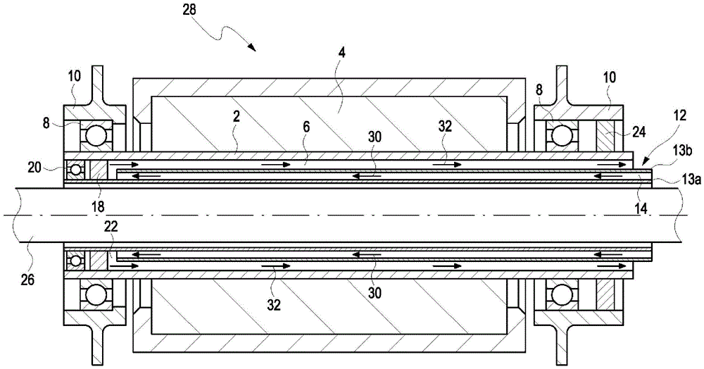
Fig. 1 shows a schematic representation of a detail of an embodiment of an electric machine according to the invention with an embodiment of a cooling system according to the invention.
Detailed Description
The detail of the electric machine, schematically shown in fig. 1, comprises: a cylindrical rotor shaft 2 for the rotor 4; a first flow space 14 for a fluid cooling medium, designed as a supply route; two bearings 8; a housing 10; a cooling jacket 12, which is arranged stationary or fixed in position on the housing 10 and comprises two cylindrical jackets 13a, 13b for cooling; a second flow space 6 designed as a return route; a first seal member 18; at least one support device 20 for the cooling jacket 12; a transition region 22 between the two flow spaces 6, 14; a second seal 24 and a cylindrical drive shaft 26.
In motor operation, the rotor 4 rotates relative to a stator, not shown in detail, at the rotational speed of the motor. The drive shaft 26 is designed to drive an external device, in this case, for example, a wheel for driving or advancing a motor vehicle, wherein the drive shaft 26 rotates at the rotational speed of the external device, in this case, the wheel.
Furthermore, the rotor shaft 2 and the drive shaft 26 are connected to one another by a transmission, which is not further shown here. The transmission is here flanged on the side to the rotor shaft 2 and the drive shaft 26. The rotor shaft 2 and the drive shaft 26 can therefore rotate simultaneously during operation at different rotational speeds, which differ by a rotational speed difference.
The drive shaft 26 is coaxially surrounded by a first flow space 14, which is designed as a supply path, and in turn is coaxially surrounded by a second flow space 6, which is designed as a return path and is coaxially surrounded by the rotor shaft 2 of the rotor 4. At least the two flow spaces 6, 14 and the transition region 22 connecting the two flow spaces 6, 14 are part of the cooling system 28 according to the invention and are used for conveying a cooling medium.
In operation of the cooling system 28, the cooling medium flows axially or in the axial direction into the first flow space 14, which is designed as a supply line, as is illustrated here by the arrow 30 in the first flow space 14. The cooling medium then flows from the first flow space 14 in the radial direction or radially from the inside to the outside through the transition region 22 into the second flow space 6, where it flows out in the axial direction from the second flow space and is additionally entrained in rotation, which is illustrated here by the arrow 32 in the second flow space 6 designed as a return path.
In the electric machine, the drive shaft 26 is arranged structurally inside the hollow rotor shaft 2 and is coaxially surrounded by the rotor shaft 2. A stationary cooling sleeve 12 is arranged in the installation space between the drive shaft 26 and the rotor shaft 2. The cooling jacket 12 comprises two cylindrical sleeves 13a, 13b arranged coaxially with one another, wherein the inner first sleeve 13a surrounds the drive shaft 26 and forms the inner wall of the first flow space 14. The outer sleeve 13b here forms the outer wall of the first flow space 14 and the inner wall of the second flow space 6. The rotor shaft 2 at the same time forms the outer wall of the second flow space 6.
In motor operation, the drive shaft 26 and the rotor shaft 2 rotate relative to each other and relative to the housing 10. Instead, the two bushings 13a, 13b of the cooling jacket 12 are fixedly connected to the housing 10 and are therefore arranged in a positionally fixed manner relative to the drive shaft 26 and the rotor shaft 2.
The outer second jacket 13b of the stationary cooling sleeve 12 therefore separates the cooling medium flowing axially into the rotor shaft 2 via the first flow channel 14 designed as a supply line from the cooling medium flowing radially out of the rotor shaft 2 via the second flow space 6 designed as a return line. In this case, the inner contour/inner contour of the outer wall of the rotor shaft 2 forming the second flow space 6 flows only in one direction, i.e., in the first direction (arrow 32). Furthermore, the two bushings 13a, 13b of the cooling jacket 12 are sealed both inside the rotor shaft 2 and outside the drive shaft 26 by seals 18, 24 and are supported by at least one support device 20 inside the rotor shaft 2.
In operation of the cooling system 28, the cooling medium can flow through the supply line and the return line without air pockets when the rotor shaft 2 is rotating and thus through the first and second flow spaces 6, 14 defined by the sleeves 13a, 13b of the cooling sleeve 12. In this case, the coolant flows into the first flow space 14, which is designed as a supply line, through the inlet having the smallest possible first cross section. This cross section as small as possible corresponds to the diameter given by the hydraulic cross section through the electric motor. This makes it possible to avoid narrow spots of the cooling medium without the cross section being larger than necessary.
In contrast, the outlet with the second cross section, which is as large as possible and is larger than the first cross section, ensures that the cooling medium flows out axially from the second flow space 6, which is designed as a return line, wherein the axially flowing-out cooling medium is set in rotation by the rotating shaft. The inlet is designed here in the form of a ring and is delimited by two sleeves 13a, 13 b. The outlet is designed here in the form of a ring and is delimited by the outer sleeve 13b and the rotor shaft 2. In the embodiment of the cooling system 28 or of the electric machine, the rotating cooling medium, for example water, which flows back (arrow 32) in this case, is provided with a cross section which is as large as possible. The larger the cross-section of the outlet of the rotating cooling medium through the flow space 6, the smaller the flow losses. This also minimizes the pressure loss of the cooling medium that may result therefrom. By setting a cross section as small as possible and a cross section as large as possible and a proportional relationship between the cross sections, the transition region 22 can be designed free of air pockets.
Due to the height level between the inlet and the outlet at the rotating rotor shaft 2, a pressure builds up in the cooling system 28 in a pump-like manner for the fluid cooling medium. The overall pressure loss of the medium due to the system is thereby reduced in the cooling system 28. During operation of the electric machine, a stationary and/or stationary liquid column for the cooling medium is obtained between the two stationary sleeves 13a, 13b which enclose the first flow space 14 and thus the supply line. Since the rotor shaft 2 together with the second sleeve 13b encloses the second flow space and thus the return line, a rotating second liquid column for the cooling medium is obtained.
The cooling medium flowing in laminar flow through the first flow region 14 only generates turbulence in the transition region 22 as a transition point to the rotor shaft 2 between the supply line and the return line or on or in the transition region 22 between the two flow regions 6, 14 on the sleeves 13a, 13b or in the stationary cooling sleeve 12. The force of the rotating liquid column of the cooling medium in the second flow region 6 is actually generated outside the second sleeve 13b of the stationary cooling sleeve 12.
Due to the coaxial arrangement of the two sleeves 13a, 13b of the stationary cooling jacket 12, the axial inflow or flow direction of the cooling medium results in a very small pressure gradient and thus a cavitation-free transition of the cooling medium between the stationary liquid column and the rotating liquid column.