CN110761237A - Evaporation heating blanket - Google Patents
Evaporation heating blanket Download PDFInfo
- Publication number
- CN110761237A CN110761237A CN201810843451.XA CN201810843451A CN110761237A CN 110761237 A CN110761237 A CN 110761237A CN 201810843451 A CN201810843451 A CN 201810843451A CN 110761237 A CN110761237 A CN 110761237A
- Authority
- CN
- China
- Prior art keywords
- guide hole
- layer
- evaporative
- blanket
- top layer
- Prior art date
- Legal status (The legal status is an assumption and is not a legal conclusion. Google has not performed a legal analysis and makes no representation as to the accuracy of the status listed.)
- Granted
Links
Images


Classifications
-
- E—FIXED CONSTRUCTIONS
- E01—CONSTRUCTION OF ROADS, RAILWAYS, OR BRIDGES
- E01H—STREET CLEANING; CLEANING OF PERMANENT WAYS; CLEANING BEACHES; DISPERSING OR PREVENTING FOG IN GENERAL CLEANING STREET OR RAILWAY FURNITURE OR TUNNEL WALLS
- E01H8/00—Removing undesirable matter from the permanent way of railways; Removing undesirable matter from tramway rails
- E01H8/02—Methods or apparatus for removing ice or snow from railway tracks, e.g. using snow-ploughs ; Devices for dislodging snow or ice which are carried or propelled by tramway vehicles ; Moving or removing ballast
-
- E—FIXED CONSTRUCTIONS
- E01—CONSTRUCTION OF ROADS, RAILWAYS, OR BRIDGES
- E01H—STREET CLEANING; CLEANING OF PERMANENT WAYS; CLEANING BEACHES; DISPERSING OR PREVENTING FOG IN GENERAL CLEANING STREET OR RAILWAY FURNITURE OR TUNNEL WALLS
- E01H8/00—Removing undesirable matter from the permanent way of railways; Removing undesirable matter from tramway rails
- E01H8/02—Methods or apparatus for removing ice or snow from railway tracks, e.g. using snow-ploughs ; Devices for dislodging snow or ice which are carried or propelled by tramway vehicles ; Moving or removing ballast
- E01H8/08—Methods or apparatus for removing ice or snow from railway tracks, e.g. using snow-ploughs ; Devices for dislodging snow or ice which are carried or propelled by tramway vehicles ; Moving or removing ballast by application of heat, e.g. by means of heated clearing instruments, melting in situ; Clearing devices which melt the dislodged snow; Clearing exclusively by means of rays or streams or gas or stream, or by suction
Landscapes
- Engineering & Computer Science (AREA)
- Architecture (AREA)
- Civil Engineering (AREA)
- Structural Engineering (AREA)
- Buildings Adapted To Withstand Abnormal External Influences (AREA)
Abstract
本发明涉及轨道运输领域,公开了一种蒸发热毯,具有沿厚度方向依次分布的底层(10)、中间层(20)和顶层(30),所述中间层(20)包括发热部(21),导热部(22)和导孔部(23),所述导孔部(23)沿所述厚度方向贯穿所述中间层(20),所述发热部(21)分布在所述导孔部(23)的周围,所述导热部(22)覆盖所述发热部(21),从而能够将蒸发热毯所覆盖部分的冰雪融化形成水汽,且使所形成的水汽能够通过导孔部容易地向顶层移动,以使水汽能够透过蒸发热毯排到外部空气中。
The invention relates to the field of rail transportation, and discloses an evaporation thermal blanket, which has a bottom layer (10), an intermediate layer (20) and a top layer (30) sequentially distributed along the thickness direction, the intermediate layer (20) including a heating part (21) ), a heat conduction part (22) and a guide hole part (23), the guide hole part (23) runs through the intermediate layer (20) in the thickness direction, and the heat generating part (21) is distributed in the guide hole The heat conduction part (22) covers the heat generating part (21), so that the ice and snow covered by the evaporation blanket can be melted to form water vapor, and the formed water vapor can easily pass through the guide hole part. The ground is moved towards the top layer so that the water vapor can be discharged to the outside air through the evaporative thermal blanket.
Description
技术领域technical field
本发明涉及轨道运输领域,具体地涉及蒸发热毯。The present invention relates to the field of rail transportation, in particular to an evaporative thermal blanket.
背景技术Background technique
随着城市化的进展,人口密集度的提高,城市道路堵塞问题日益严重。城市轨道运输成为了解决这问题的主要手段,从定义上而言,城市轨道运输是指在城市及附近地区,以列车形式沿封闭或者部分封闭的专用轨道按班次运行的各种公共客运交通方式的总称,包括地铁系统、轻轨系统、单轨系统、有轨电车等。With the progress of urbanization and the increase of population density, the problem of urban road congestion is becoming more and more serious. Urban rail transportation has become the main means to solve this problem. By definition, urban rail transportation refers to various public passenger transportation modes that operate in the form of trains along closed or partially closed dedicated tracks in the city and nearby areas. The general term for the subway system, the light rail system, the monorail system, the tram, etc.
单轨系统是指以单一轨道梁支撑或者悬挂车厢并提供引导作用而运行的轨道系统。其中,轨道梁不仅是车辆的承重结构,同时也是车辆运行的导向轨道。单轨系统的类型主要有两种,一种是车辆跨骑在轨道梁上运行的方式,称之为跨座式单轨系统;另一种是悬挂在轨道梁上运行的方式,称之为悬挂式单轨系统。The monorail system refers to a rail system that supports or suspends the carriage with a single rail beam and provides guidance. Among them, the track beam is not only the load-bearing structure of the vehicle, but also the guiding track for the vehicle to run. There are two main types of monorail systems, one is the way in which the vehicle straddles the track beam, which is called the straddle type monorail system; the other is the way of running on the track beam, which is called the suspension type. Monorail system.
现在,轨道梁主要通常采用预应力混凝土制成,也称之为PC梁,一些特殊的区段也可采用钢结构的轨道梁,或者,几种材料组成的复合梁体。Now, track beams are usually made of prestressed concrete, also known as PC beams, and some special sections can also be steel-structured track beams, or composite beams composed of several materials.
由于跨座式单轨列车是跨骑于轨道梁上行驶,因此轨道梁的顶面作为行走面,其与列车车辆下部承托车体的行走轮直接接触,需要确保行走面的状态。特别是在冬季的低气温环境、或者下雪天气时,需要对行走面进行除冰雪。Since the straddle-type monorail runs on the track beam, the top surface of the track beam is used as the running surface, which is in direct contact with the running wheels of the lower part of the train vehicle supporting the car body, and the state of the running surface needs to be ensured. Especially in the low temperature environment in winter or in snowy weather, it is necessary to remove ice and snow from the walking surface.
发明内容SUMMARY OF THE INVENTION
本发明的目的是为了克服现有技术存在的无法在低温地区、多雨雪地区可靠地确保轨道梁的走行面状态的问题,提供蒸发热毯,该蒸发热毯能够高效可靠地进行除雪,以确保轨道梁的行走面的不存在冰层,防止行走轮因冰层而打滑和空转,从而可靠地保证单轨列车运行安全。The purpose of the present invention is to overcome the problem of the prior art that the running surface state of the track beam cannot be reliably ensured in low temperature areas, rainy and snowy areas, and to provide an evaporative thermal blanket, which can efficiently and reliably remove snow, and Ensure that there is no ice layer on the running surface of the track beam, prevent the running wheel from slipping and idling due to the ice layer, thereby reliably ensuring the safe operation of the monorail.
为了实现上述目的,本发明一方面提供一种蒸发热毯,具有沿厚度方向依次分布的底层、中间层和顶层,所述中间层包括发热部,导热部和导孔部,所述导孔部沿所述厚度方向贯穿所述中间层,所述发热部分布在所述导孔部的周围,所述导热部覆盖所述发热部。In order to achieve the above object, one aspect of the present invention provides an evaporation thermal blanket, which has a bottom layer, an intermediate layer and a top layer sequentially distributed along the thickness direction, the intermediate layer including a heating part, a heat conduction part and a guide hole part, the guide hole part The intermediate layer is penetrated in the thickness direction, the heat generating portion is distributed around the guide hole portion, and the heat conducting portion covers the heat generating portion.
优选地,所述导孔部包括沿蒸发热毯的长度方向均匀分布的多个导孔列,所述导孔列包括沿蒸发热毯的宽度方向均匀分布的多个导孔,所述发热部包括沿所述长度方向往复延伸的第一发热丝,和沿所述宽度方向往复延伸的第二发热丝,所述第一发热丝和所述第二发热丝之间设置有绝缘层。Preferably, the guide hole portion includes a plurality of guide hole rows evenly distributed along the length direction of the thermal evaporation blanket, the guide hole row includes a plurality of guide holes evenly distributed along the width direction of the thermal evaporation blanket, and the heat generating portion It includes a first heating wire extending back and forth along the length direction, and a second heating wire extending back and forth along the width direction, and an insulating layer is arranged between the first heating wire and the second heating wire.
优选地,所述第一发热丝分布在相邻所述导孔列之间,且具有第一正极端和第一负极端,所述第二发热丝分布在相邻所述导孔之间,且具有第二正极端和第二负极端,所述第一负极端和所述第二正极端连接。Preferably, the first heating wire is distributed between adjacent rows of the guide holes, and has a first positive terminal and a first negative terminal, and the second heating wire is distributed between the adjacent guide holes, and has a second positive terminal and a second negative terminal, the first negative terminal and the second positive terminal are connected.
优选地,所述顶层包括由热反射材料形成的顶层主体部,和分布在所述顶层主体部中的至少一个贯通所述顶层主体部的引导孔,所述引导孔与所述导孔部连通。Preferably, the top layer comprises a top layer main body part formed of a heat reflective material, and at least one guide hole distributed in the top layer main body part and penetrating the top layer main part, the guide hole communicates with the guide hole part .
优选地,所述顶层为闭孔泡沫塑料,所述顶层上设置有多个引导孔,该多个引导孔与所述导孔部重合。Preferably, the top layer is a closed-cell foam plastic, and a plurality of guide holes are provided on the top layer, and the plurality of guide holes coincide with the guide hole portion.
优选地,所述底层包括底层主体部,设置在所述底层主体部上的多个轨道梁设置部,和设置在所述底层主体部中的多个导出孔,所述导出孔与所述导孔部连通。Preferably, the bottom layer includes a bottom layer main body part, a plurality of rail beam setting parts provided on the bottom layer main body part, and a plurality of lead-out holes provided in the bottom layer main body part, the lead-out holes and the guide The holes are connected.
优选地,所述轨道梁设置部为长形磁条,所述长形磁条沿所述长度方向延伸。Preferably, the rail beam setting portion is an elongated magnetic strip, and the elongated magnetic strip extends along the length direction.
优选地,所述底层为防水透气膜,所述底层上设置有多个导出孔,该多个导出孔与所述导孔部重合。Preferably, the bottom layer is a waterproof and breathable membrane, and a plurality of lead-out holes are provided on the bottom layer, and the plurality of lead-out holes overlap with the guide hole portion.
优选地,所述底层和所述中间层之间、所述中间层和所述顶层之间均通过粘结层粘接。Preferably, the bottom layer and the middle layer, and the middle layer and the top layer are all bonded by an adhesive layer.
优选地,所述蒸发热毯的长度方向的一端设置有回收接合部,所述回收接合部能够可释放地接合在蒸发热毯卷收装置中的卷辊上。Preferably, one end of the evaporative thermal blanket in the length direction is provided with a recovery joint portion, and the recovery joint portion can be releasably engaged on the roll in the evaporative thermal blanket winding device.
通过上述技术方案,中间层能够将蒸发热毯所覆盖部分的冰雪融化形成水汽,且使所形成的水汽能够通过导孔部容易地向顶层移动,以使水汽能够透过蒸发热毯排到外部空气中。Through the above technical solution, the middle layer can melt the ice and snow covered by the evaporative thermal blanket to form water vapor, and the formed water vapor can easily move to the top layer through the guide hole portion, so that the water vapor can be discharged to the outside through the evaporative thermal blanket in the air.
附图说明Description of drawings
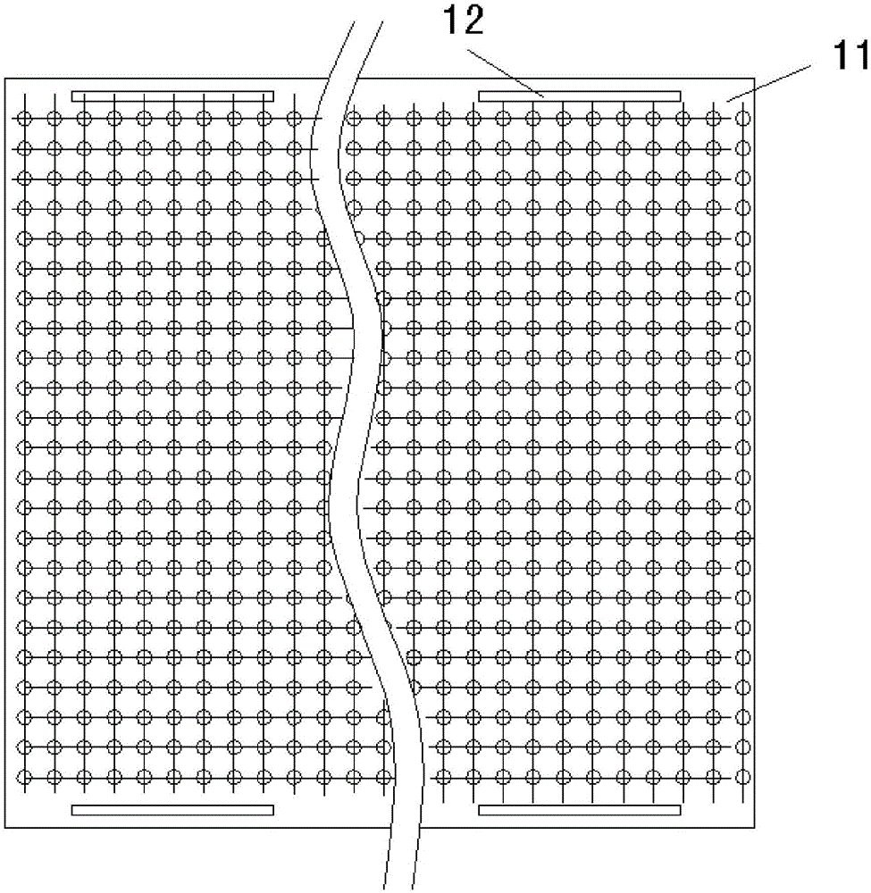
图1是本发明所述蒸发热毯的仰视图(从底层观察);Fig. 1 is the bottom view (viewed from the bottom layer) of the evaporative thermal blanket of the present invention;
图2是本发明所述蒸发热毯的结构示意图;Fig. 2 is the structural representation of the evaporation thermal blanket of the present invention;
图3是本发明所述蒸发热毯沿图2的A-A位置的剖视图;Fig. 3 is the sectional view of the evaporation thermal blanket of the present invention along the A-A position of Fig. 2;
图4是本发明所述蒸发热毯铺设到轨道梁时的状态示意图;Fig. 4 is the state schematic diagram when the evaporative thermal blanket of the present invention is laid on the track beam;
图5是能够对本发明所述蒸发热毯进行卷收的蒸发热毯卷收装置的结构示意图。FIG. 5 is a schematic structural diagram of the evaporative thermal blanket winding device capable of winding the evaporative thermal blanket according to the present invention.
附图标记说明Description of reference numerals
1、轨道梁; 2、蒸发热毯;1. Track beam; 2. Evaporation thermal blanket;
3、电缆线; 4、卷辊;3. Cable; 4. Roller;
5、车架;5. Frame;
10、底层; 11、底层主体部;10. The bottom layer; 11. The main body of the bottom layer;
12、轨道梁设置部; 13、导出孔;12. Track beam setting part; 13. Export hole;
20、中间层; 21、发热部;20. Middle layer; 21. Heating part;
22、导热部; 23、导孔部;22. Heat conduction part; 23. Guide hole part;
30、顶层; 31、顶层主体部;30. The top layer; 31. The main body of the top layer;
32、空腔; 33、引导孔。32. Cavity; 33. Guide hole.
具体实施方式Detailed ways
以下结合附图对本发明的具体实施方式进行详细说明。应当理解的是,此处所描述的具体实施方式仅用于说明和解释本发明,并不用于限制本发明。The specific embodiments of the present invention will be described in detail below with reference to the accompanying drawings. It should be understood that the specific embodiments described herein are only used to illustrate and explain the present invention, but not to limit the present invention.
在本发明中,在未作相反说明的情况下,使用的方位词如“上、下、左、右”通常是指参考附图的上、下、左、右。“内、外”是指相对于部件本身轮廓的内、外。此外,在本发明的描述中,“多个”的含义是至少两个,例如两个,三个等,除非另有明确具体的限定。In the present invention, unless otherwise stated, the directional words used such as "upper, lower, left and right" generally refer to upper, lower, left and right with reference to the drawings. "Inside and outside" means inside and outside relative to the contour of the part itself. In addition, in the description of the present invention, "plurality" means at least two, such as two, three, etc., unless expressly and specifically defined otherwise.
本发明提供一种蒸发热毯,如图1-3所示,具有沿厚度方向依次分布的底层10、中间层20和顶层30。中间层20包括发热部21,导热部22和导孔部23,其中,导孔部23沿厚度方向贯穿中间层20,发热部21分布在导孔部23的周围,导热部22覆盖发热部21,发热部21能够通过导热部22以及底层10将蒸发热毯所覆盖部分的冰雪融化形成水汽,所形成的水汽能够通过导孔部23容易地向顶层30移动,以使水汽能够容易地透过蒸发热毯排到外部空气中。为了便于描述,下面将冰雪被蒸发热毯所覆盖部分的表面称之为“待处理表面”。The present invention provides an evaporation thermal blanket, as shown in FIGS. 1-3 , having a
换言之,本发明通过在中间层20中同时设置发热部21和导孔部23为水汽提供了向外蒸发排出的定向动力,该定向动力能够有效地将水汽从底层附近引导至顶层,进行排出,从而能够可靠地改变待处理表面的湿度状态。In other words, the present invention provides directional power for water vapor to evaporate and discharge outward by providing the
本发明所述蒸发热毯不但能够使所覆盖部分的冰雪融化,而且能够使待处理表面形成相对干燥的状态,避免蒸发热毯撤离后,附着在行走面上的水汽等再次结冰,从而快速可靠地进行轨道梁的保养。The evaporative thermal blanket of the present invention can not only melt the covered part of the ice and snow, but also can make the surface to be treated into a relatively dry state, so as to avoid the water vapor adhering to the walking surface from freezing again after the evacuation of the evaporative thermal blanket, so as to quickly Reliable maintenance of track beams.
其中,优选底层10为由具有耐折、防水、抗拉的性能的材料形成防水导热层。防水导热层的防水性主要是指从底层到顶层的方向而言,其能够使由待处理表面处冰雪所生成的水汽不会透过底层10进入发热部21处,而通过导孔部23这一通道排出到外部空气中。另外,防水导热层的导热性主要是指从顶层到底层方向而言,其能够使发热部所产生的热快速地传递到待处理表面,进行冰雪的融化蒸发。Among them, it is preferable that the
顶层30为有具有保温、透气性能的材料形成的保温透气层。保温透气层的保温性主要是指从底层到顶层的方向而言,其能够在一定程度上防止发热部21所产生的热量通过顶层30进入到外部空气中,以提高发热部的热效率。保温透气层的透气性主要是指从顶层到底层的方向而言,其能够将经过中间层20的水汽尽快地排出外部空气中。The
发热部21是指产生或制造出高温的装置,常使用利用电能达到加热效果的装置,例如电阻丝加热等。导热部22覆盖发热部21上,以将发热部21 所产热能均匀地向待处理表面释放。另外,导孔部23开设在未设置有发热部21的导热部22上。The
导孔部23为多个沿厚度方向贯穿的导孔,能够以各种方式排布在中间层上,只要其不影响发热部21即可。作为一种优选实施方式,如图3所示,导孔部23包括沿长度方向均匀分布的多个导孔列,所述导孔列包括沿宽度方向均匀分布的多个导孔。即,通过将多个导孔排布为沿纵横方向均匀排布的矩阵状,以使所述定向动力相对均匀,从而提高待处理表面的处理效率。The
另外,导孔能够为各种形状,例如矩形孔,三角孔等,优选为圆孔。所述导孔部22沿所述厚度方向贯穿中间层20是指,导孔的轴线(导孔的延伸方向)大致垂直于底层或者顶层,也能够分别倾斜不同的角度,只要使导孔的一端与底层10接触,另一端与顶层接触即可。In addition, the guide hole can be of various shapes, such as a rectangular hole, a triangular hole, etc., preferably a circular hole. The
另外,也能够使导孔部23中的所有导孔倾斜相同角度,从而更加地便于蒸发热毯的卷收。In addition, all the guide holes in the
另外,当发热部21为利用电能达到加热效果的电阻丝时,即发热部21 包括沿长度方向往复延伸的第一发热丝,和沿宽度方向往复延伸的第二发热丝,第一发热丝和第二发热丝之间设置有绝缘层。In addition, when the
具体地,第一发热丝和第二发热丝是由镍铬合金等形成的电阻率较高,塑性较好,易弯曲的电阻丝。此时,导热部22采用高弹性、绝缘性好的橡胶材料,另外,利用该橡胶材料作为绝缘层。该绝缘层将传递横向电流的第一发热丝和传递纵向电流的第二发热丝隔开。导热部22和发热部21设置方式能够为多种,例如导热部22能够为三个橡胶片材,传递横向电流的第一发热丝和传递纵向电流的第二发热丝以橡胶片材隔开进行绝缘,以避免纵横交错的第一发热丝和第二发热丝的交叉处电连接。Specifically, the first heating wire and the second heating wire are formed of nickel-chromium alloys with high resistivity, good plasticity, and easy to bend. In this case, the thermally
第一发热丝沿长度方向在导孔列之间往复延伸,可以间隔两排、三排等导孔列进行往复延伸,从而灵活地调整电阻丝的布置密度。类似地,第二发热丝沿宽度方向在导孔之间往复延伸,可以间隔两排、三排等导孔列进行往复延伸,从而灵活地调整电阻丝的布置密度。另外,也可以设置沿45度方向的斜向往复延伸的第三发热丝等,以进一步地调整电阻丝的布置密度。The first heating wire extends back and forth between the guide hole rows along the length direction, and can be extended back and forth between two or three rows of guide hole rows, so as to flexibly adjust the arrangement density of the resistance wires. Similarly, the second heating wire extends back and forth between the guide holes in the width direction, and can be extended back and forth between two or three rows of guide holes, so as to flexibly adjust the arrangement density of the resistance wires. In addition, a third heating wire extending back and forth in a 45-degree oblique direction can also be provided, so as to further adjust the arrangement density of the resistance wires.
作为本发明的优选实施方式,第一发热丝分布在相邻所述导孔列之间,且具有第一正极端和第一负极端,所述第二发热丝分布在相邻所述导孔之间,且具有第二正极端和第二负极端。通过上述往复延伸方式,第一发热丝和第二发热丝交叉成格子,在每个导孔周围均围绕有发热丝。即,除靠近蒸发热毯的边缘最近的导孔列,和导孔列两端的导孔之外,每相邻的两个导孔之间均匀分布有电阻丝,从而提高加热的均匀性,使定向动力更加均匀,更有效地对待处理表面上冰雪进行处理。As a preferred embodiment of the present invention, the first heating wire is distributed between adjacent rows of the guide holes and has a first positive terminal and a first negative terminal, and the second heating wire is distributed between the adjacent guide holes between, and has a second positive terminal and a second negative terminal. Through the above-mentioned reciprocating extension method, the first heating wire and the second heating wire are crossed into a lattice, and the heating wire is surrounded around each guide hole. That is, except for the guide hole row closest to the edge of the evaporation thermal blanket and the guide holes at both ends of the guide hole row, resistance wires are evenly distributed between every two adjacent guide holes, so as to improve the uniformity of heating and make the The directional power is more uniform and more efficient in handling snow and ice on the surface to be treated.
另外,第一发热丝的第一负极端和第二发热丝的第二正极端电连接,第一发热丝和第二发热丝形成一条连续的发热丝,从而使发热部21只有一个正极和负极,便于与电缆线3等的连接。具体地第一负极端和第二正极端在蒸发热毯的端部处连接。In addition, the first negative terminal of the first heating wire is electrically connected to the second positive terminal of the second heating wire, and the first heating wire and the second heating wire form a continuous heating wire, so that the
如图2为本发明所述蒸发热毯的一种具体实施方式的剖视图,由于导孔尺寸相对蒸发热毯的整体尺寸较小,因此,该图2所示为1个导孔及其周边部分的结构示意图。FIG. 2 is a cross-sectional view of a specific embodiment of the thermal evaporation blanket according to the present invention. Since the size of the guide holes is relatively small compared to the overall size of the thermal evaporation blanket, FIG. 2 shows one guide hole and its surrounding parts. Schematic diagram of the structure.
作为保温透气层的顶层,优选顶层30包括由热反射材料形成的顶层主体部31,且分布有至少一个贯通所述顶层30的引导孔33,引导孔33与导孔部23连通。顶层主体部31为聚酰亚胺薄膜或者铝箔。As the top layer of the thermal insulation and breathable layer, preferably the
作为保温透气层的顶层,也能优选顶层30包括顶层主体部31,设置在顶层主体部31中分布有至少一个空腔32和至少一个贯通顶层30的引导孔 33,和设置在底层主体部31中的多个引导孔33。由于空腔32中封闭有空气,而在小空间内静止的空气具有良好的保温性能,因而能够起到良好的保温效果。另外,通过设置与导孔部23连通的引导孔33,能够使经过导孔部23 的水汽经引导孔33导出到外部空气中,减少了水汽向外排出的阻力,即进一步地提高了定向动力。As the top layer of the thermal insulation and breathable layer, it is also preferred that the
具体地,顶层30为经发泡成型加工成的片状体,根据发泡成型工艺,若形成的绝大多数气孔是互相连通的,则称为开孔泡沫塑料,此时,这些开孔也能够与导孔部23连通,而起到将水汽导出到外部空气中的作用,则不必单独开设引导孔33。Specifically, the
作为本发明的优选实施方式,顶层30为闭孔泡沫塑料,顶层30上设置有与导孔部23相应设置的多个引导孔33。该引导孔33能够在作为顶层30 的层状体粘结到中间层20、底层10上之后,通过开孔装置,与导出孔13、导孔(导孔部23)一起打孔形成。即顶层主体部31为热固性和热塑性塑料,例如聚苯乙烯、聚氨酯、聚氯乙烯、聚乙烯、脲甲醛、酚醛等。通过发泡成型在顶层主体部31中形成空腔32,通过机械打孔形成与导孔部23一一对应的引导孔33。优选为具有轻量化特性的发泡聚乙烯材料。As a preferred embodiment of the present invention, the
如图2所示,作为防水导热层的底层,优选底层10包括底层主体部11,设置在底层主体部11上的多个轨道梁设置部12,和设置在底层主体部11 中的多个导出孔13。如图由于在底层主体部11上设置有轨道梁设置部12 能够使蒸发热毯与轨道梁贴合,从而提高加热蒸发效率。另外,通过设置与导孔部23连通的导出孔13,能够使在待处理表面融化蒸发而成的水汽能够导出至导孔部23,从而迅速地向外部空气中转移。As shown in FIG. 2 , as the bottom layer of the waterproof and heat-conducting layer, it is preferable that the
轨道梁设置部12能够为各种结构,例如只要其能够与轨道梁1贴合即可,例如,轨道梁设置部12能够为比重相对较重的材料,且所设置的边缘部的位置之间的距离大于轨道梁1的宽度,从而能够在铺设到位后利用重力使边缘部垂挂在轨道梁的两侧,从而使蒸发热毯1贴合在待处理表面上,形成如图4所示的状态。The rail
优选轨道梁设置部12为长形磁条,所述长形磁条沿所述长度方向分布,从而能够在蒸发热毯铺设到位后利用长形磁条的磁力与轨道梁吸合而扣紧。且优选所设置的边缘部的位置之间的距离大于轨道梁1的宽度,与轨道梁的侧边吸合扣紧。如上所述由于轨道梁设置部12在设置到后位于轨道梁侧侧边,因而,能够使得发热部21和导孔部23铺设在轨道梁1的行走面的整个宽度上,从而可靠地确保轨道梁1的行走面上的冰雪有效处理,防止在行走面边缘处残留。Preferably, the rail
另外,底层10为防水透气膜。在水汽状态时,呈细小状态的水颗粒,能够利用毛细运动的原理,可以顺利渗透到毛细管到另一侧,从而发生透汽现象。当水汽冷凝变成水珠后,颗粒变大,由于水珠表面张力的作用(水分子之间互相“拉扯抗衡”),水分子就不能顺利脱离水珠渗透到另一侧,也就是防止了水的渗透发生,使透气膜有了防水的功能。在本发明中,采用 EPTFE,即聚四氟乙烯,其具有高抗拉强度,高弹性和延伸率的特点。In addition, the
另外,在底层10上所设置的多个导出孔13优选与导孔部23相应设置。导出孔13能够在作为底层10的防水透气膜粘结到中间层20、顶层30上之后,通过开孔装置,与引导孔33、导孔(导孔部23)一起打孔形成。In addition, the plurality of lead-out
另外,底层10和中间层20之间、中间层20和顶层30之间均通过粘结层40粘接。粘结层40优选分布在中间层20的整个接触面上。另外,优选所述蒸发热毯的长度方向的一端设置有回收接合部,所述回收接合部能够可释放地接合在蒸发热毯卷收装置中的卷辊4上,以利用卷辊4拾起蒸发热毯的端部,进行卷收。In addition, the
作为蒸发热毯卷收装置的一种具体实施方式,如图5所示,蒸发热毯卷收装置的行走结构设置在车架5上,其与轨道列车类似,使蒸发热毯卷收装置能够在轨道梁1上移动,卷辊4分别设置在蒸发热毯卷收装置的两侧,一侧用于卷收,一侧用于覆盖。具体地,车架5采用大梁结构,从而有能力承载较多的蒸发热毯,用于进行卷收和覆盖的蒸发热毯均位于装置内部。As a specific implementation of the evaporative thermal blanket winding device, as shown in FIG. 5 , the running structure of the evaporative thermal blanket winding device is set on the
本发明所述蒸发热毯的宽度方向和长度方向的尺寸能够更加轨道梁1和蒸发热毯卷收装置中卷辊4的直径,以及蒸发热毯本身的可曲性等设置,蒸发热毯的厚度方向的尺寸能够根据实际使用环境温度设置。The dimensions in the width direction and the length direction of the evaporation thermal blanket according to the present invention can be set according to the diameter of the
作为一种具体实施方式,蒸发热毯的尺寸能够为宽度1m、长度500m、厚度3mm,蒸发热毯的发热部21的工作温度为80℃。底层10、中间层20 和顶层30能够形成相同的厚度,即可为1mm。另外,中间层的厚度根据电热丝的直径设置,因用作绝缘层的橡胶需覆盖整个电热丝,即中间层的厚度需要大于电热丝的直径。As a specific embodiment, the size of the evaporation thermal blanket can be 1 m in width, 500 m in length, and 3 mm in thickness, and the working temperature of the
如上所述,本发明所述蒸发热毯具有绝缘性、保温性、透气性、轻量性等特点。当轨道梁上积有冰雪时,通过覆盖蒸发热毯,利用发热部21融化冰雪,利用导孔部23将蒸发的水汽通过孔排到外部空气,而且本身质量较轻,有利于覆盖作业的进行。As mentioned above, the evaporative thermal blanket of the present invention has the characteristics of insulation, heat preservation, air permeability, light weight and the like. When there is ice and snow on the track beam, the
而且由于蒸发热毯具有能够保温的顶层30,因而,相比于热吹风、发热管发热的方式,其能够在一定程度上防止发热部21所产生的热量通过顶层 30进入到外部空气中,能够提高发热部的热效率,具有良好的节能性。Moreover, since the evaporative thermal blanket has a
当轨道列车不运营时,蒸发热毯卷收装置在轨道梁1上行走,将蒸发热毯2铺设在轨道梁1的行走面上,通过电缆线3通电,使发热部21发热,热量传递至轨道梁上,轨道梁上表面(待处理表面)的冰雪融化,水汽透过蒸发热毯散发到空气中。利用本发明所述蒸发热毯2覆盖在轨道梁上表面上一段时间后,不但能够将冰雪融化,而且能够使水汽经蒸发热毯导出,因而蒸发热毯和轨道梁上表面之间不会留有水汽等,能够防止二次结冰。When the rail train is not in operation, the evaporative blanket winding device walks on the
当轨道列车运营时,利用蒸发热毯卷收装置收回蒸发热毯,此时,由于轨道梁上的冰雪基本被消除干净,且相对较为干燥,因而即使在撤除蒸发热毯后,其轨道梁上表面也不会形成冰层影响轨道列车的正常运营。When the rail train is in operation, the evaporative thermal blanket is retracted by the evaporative thermal blanket retracting device. At this time, since the ice and snow on the track beams are basically eliminated and relatively dry, even after the evaporative thermal blankets are removed, the evaporative thermal blankets on the track beams are still relatively dry. No ice formation on the surface will affect the normal operation of rail trains.
以上结合附图详细描述了本发明的优选实施方式,但是,本发明并不限于此。在本发明的技术构思范围内,可以对本发明的技术方案进行多种简单变型,包括各个具体技术特征以任何合适的方式进行组合。为了避免不必要的重复,本发明对各种可能的组合方式不再另行说明。但这些简单变型和组合同样应当视为本发明所公开的内容,均属于本发明的保护范围。The preferred embodiments of the present invention have been described above in detail with reference to the accompanying drawings, however, the present invention is not limited thereto. Within the scope of the technical concept of the present invention, various simple modifications can be made to the technical solutions of the present invention, including the combination of various specific technical features in any suitable manner. In order to avoid unnecessary repetition, the present invention will not describe various possible combinations. However, these simple modifications and combinations should also be regarded as the contents disclosed in the present invention, and all belong to the protection scope of the present invention.
Claims (10)
Priority Applications (1)
| Application Number | Priority Date | Filing Date | Title |
|---|---|---|---|
| CN201810843451.XA CN110761237B (en) | 2018-07-27 | 2018-07-27 | Evaporation heating blanket |
Applications Claiming Priority (1)
| Application Number | Priority Date | Filing Date | Title |
|---|---|---|---|
| CN201810843451.XA CN110761237B (en) | 2018-07-27 | 2018-07-27 | Evaporation heating blanket |
Publications (2)
| Publication Number | Publication Date |
|---|---|
| CN110761237A true CN110761237A (en) | 2020-02-07 |
| CN110761237B CN110761237B (en) | 2021-05-14 |
Family
ID=69327814
Family Applications (1)
| Application Number | Title | Priority Date | Filing Date |
|---|---|---|---|
| CN201810843451.XA Active CN110761237B (en) | 2018-07-27 | 2018-07-27 | Evaporation heating blanket |
Country Status (1)
| Country | Link |
|---|---|
| CN (1) | CN110761237B (en) |
Citations (8)
| Publication number | Priority date | Publication date | Assignee | Title |
|---|---|---|---|---|
| CN2629380Y (en) * | 2003-07-03 | 2004-07-28 | 程崇钧 | Electric heating pad |
| CN101230555A (en) * | 2008-02-22 | 2008-07-30 | 卢启纯 | Heatable road |
| CN201271045Y (en) * | 2008-09-02 | 2009-07-15 | 王锐 | Energy-saving electric heating blanket |
| CN202211542U (en) * | 2011-09-05 | 2012-05-09 | 刘紫轩 | Snow-removing floor mat |
| CN103216049A (en) * | 2013-03-23 | 2013-07-24 | 梁艳芬 | Novel snow melter |
| CN203654099U (en) * | 2013-12-13 | 2014-06-18 | 中铁工程设计咨询集团有限公司 | PC track beam ice and snow melting device and PC track beam |
| CN104955180A (en) * | 2014-03-25 | 2015-09-30 | 新昌县鸿裕工业产品设计有限公司 | Net-shaped snow accumulation preventing device |
| CA2851697A1 (en) * | 2014-05-12 | 2015-11-12 | Vikram Kondathasula | A snow melting mat system |
-
2018
- 2018-07-27 CN CN201810843451.XA patent/CN110761237B/en active Active
Patent Citations (8)
| Publication number | Priority date | Publication date | Assignee | Title |
|---|---|---|---|---|
| CN2629380Y (en) * | 2003-07-03 | 2004-07-28 | 程崇钧 | Electric heating pad |
| CN101230555A (en) * | 2008-02-22 | 2008-07-30 | 卢启纯 | Heatable road |
| CN201271045Y (en) * | 2008-09-02 | 2009-07-15 | 王锐 | Energy-saving electric heating blanket |
| CN202211542U (en) * | 2011-09-05 | 2012-05-09 | 刘紫轩 | Snow-removing floor mat |
| CN103216049A (en) * | 2013-03-23 | 2013-07-24 | 梁艳芬 | Novel snow melter |
| CN203654099U (en) * | 2013-12-13 | 2014-06-18 | 中铁工程设计咨询集团有限公司 | PC track beam ice and snow melting device and PC track beam |
| CN104955180A (en) * | 2014-03-25 | 2015-09-30 | 新昌县鸿裕工业产品设计有限公司 | Net-shaped snow accumulation preventing device |
| CA2851697A1 (en) * | 2014-05-12 | 2015-11-12 | Vikram Kondathasula | A snow melting mat system |
Also Published As
| Publication number | Publication date |
|---|---|
| CN110761237B (en) | 2021-05-14 |
Similar Documents
| Publication | Publication Date | Title |
|---|---|---|
| CN109436338B (en) | Anti-icing device and anti-icing control method based on the device | |
| CA2854358C (en) | Frost resistant surface | |
| CN103233410B (en) | A kind of permeable asphalt cement concrete road surface structure with heating function | |
| US10252807B2 (en) | Runback control | |
| CN206245179U (en) | Bridge on highway section snow melting facility | |
| US20070250025A1 (en) | Composite structural/thermal mat system | |
| CN110761237B (en) | Evaporation heating blanket | |
| CN208739441U (en) | Anti- deicing laminated film | |
| CN213566509U (en) | A kind of graphene film electric heating deicing device | |
| CN101512071A (en) | Bearer and method for heating guiding elements on a bearer | |
| CN110485359B (en) | Railway rails freezes disaster and handles with disposable coating structure | |
| CN106672250A (en) | Enhanced water capture systems for aircraft interiors | |
| CN208733012U (en) | Multizone prevents and kill off ina thin film | |
| JP6718239B2 (en) | Snow melting device for railway vehicles | |
| CN205076024U (en) | An electric anti-icing skin structure | |
| CN103911934A (en) | Snow thawing apparatus | |
| CN223688866U (en) | Railway locking frame heating device | |
| CN223714187U (en) | A graphene-based snow melting heating pad | |
| JP3692355B2 (en) | Snow melting equipment | |
| CN210737238U (en) | Infrared directional radiation heating device for railway turnout | |
| CN210264060U (en) | Police shelter for cold environment | |
| JP3210366U (en) | Snow melting heater for roof valley | |
| JP7162212B2 (en) | Rooftop snow melting device | |
| JP2025028821A (en) | Insulation blanket assembly and method | |
| RU112100U1 (en) | VEHICLE CABIN ROOF SUN COVERING |
Legal Events
| Date | Code | Title | Description |
|---|---|---|---|
| PB01 | Publication | ||
| PB01 | Publication | ||
| SE01 | Entry into force of request for substantive examination | ||
| SE01 | Entry into force of request for substantive examination | ||
| GR01 | Patent grant | ||
| GR01 | Patent grant |