CN110901057A - Photocuring 3D printing system - Google Patents
Photocuring 3D printing system Download PDFInfo
- Publication number
- CN110901057A CN110901057A CN201911347069.0A CN201911347069A CN110901057A CN 110901057 A CN110901057 A CN 110901057A CN 201911347069 A CN201911347069 A CN 201911347069A CN 110901057 A CN110901057 A CN 110901057A
- Authority
- CN
- China
- Prior art keywords
- printing
- layer
- spreader
- light
- spreading
- Prior art date
- Legal status (The legal status is an assumption and is not a legal conclusion. Google has not performed a legal analysis and makes no representation as to the accuracy of the status listed.)
- Granted
Links
Images



Classifications
-
- B—PERFORMING OPERATIONS; TRANSPORTING
- B29—WORKING OF PLASTICS; WORKING OF SUBSTANCES IN A PLASTIC STATE IN GENERAL
- B29C—SHAPING OR JOINING OF PLASTICS; SHAPING OF MATERIAL IN A PLASTIC STATE, NOT OTHERWISE PROVIDED FOR; AFTER-TREATMENT OF THE SHAPED PRODUCTS, e.g. REPAIRING
- B29C64/00—Additive manufacturing, i.e. manufacturing of three-dimensional [3D] objects by additive deposition, additive agglomeration or additive layering, e.g. by 3D printing, stereolithography or selective laser sintering
- B29C64/10—Processes of additive manufacturing
- B29C64/106—Processes of additive manufacturing using only liquids or viscous materials, e.g. depositing a continuous bead of viscous material
- B29C64/124—Processes of additive manufacturing using only liquids or viscous materials, e.g. depositing a continuous bead of viscous material using layers of liquid which are selectively solidified
- B29C64/129—Processes of additive manufacturing using only liquids or viscous materials, e.g. depositing a continuous bead of viscous material using layers of liquid which are selectively solidified characterised by the energy source therefor, e.g. by global irradiation combined with a mask
-
- B—PERFORMING OPERATIONS; TRANSPORTING
- B29—WORKING OF PLASTICS; WORKING OF SUBSTANCES IN A PLASTIC STATE IN GENERAL
- B29C—SHAPING OR JOINING OF PLASTICS; SHAPING OF MATERIAL IN A PLASTIC STATE, NOT OTHERWISE PROVIDED FOR; AFTER-TREATMENT OF THE SHAPED PRODUCTS, e.g. REPAIRING
- B29C64/00—Additive manufacturing, i.e. manufacturing of three-dimensional [3D] objects by additive deposition, additive agglomeration or additive layering, e.g. by 3D printing, stereolithography or selective laser sintering
- B29C64/20—Apparatus for additive manufacturing; Details thereof or accessories therefor
-
- B—PERFORMING OPERATIONS; TRANSPORTING
- B29—WORKING OF PLASTICS; WORKING OF SUBSTANCES IN A PLASTIC STATE IN GENERAL
- B29C—SHAPING OR JOINING OF PLASTICS; SHAPING OF MATERIAL IN A PLASTIC STATE, NOT OTHERWISE PROVIDED FOR; AFTER-TREATMENT OF THE SHAPED PRODUCTS, e.g. REPAIRING
- B29C64/00—Additive manufacturing, i.e. manufacturing of three-dimensional [3D] objects by additive deposition, additive agglomeration or additive layering, e.g. by 3D printing, stereolithography or selective laser sintering
- B29C64/20—Apparatus for additive manufacturing; Details thereof or accessories therefor
- B29C64/205—Means for applying layers
- B29C64/218—Rollers
-
- B—PERFORMING OPERATIONS; TRANSPORTING
- B29—WORKING OF PLASTICS; WORKING OF SUBSTANCES IN A PLASTIC STATE IN GENERAL
- B29C—SHAPING OR JOINING OF PLASTICS; SHAPING OF MATERIAL IN A PLASTIC STATE, NOT OTHERWISE PROVIDED FOR; AFTER-TREATMENT OF THE SHAPED PRODUCTS, e.g. REPAIRING
- B29C64/00—Additive manufacturing, i.e. manufacturing of three-dimensional [3D] objects by additive deposition, additive agglomeration or additive layering, e.g. by 3D printing, stereolithography or selective laser sintering
- B29C64/20—Apparatus for additive manufacturing; Details thereof or accessories therefor
- B29C64/264—Arrangements for irradiation
- B29C64/286—Optical filters, e.g. masks
-
- B—PERFORMING OPERATIONS; TRANSPORTING
- B33—ADDITIVE MANUFACTURING TECHNOLOGY
- B33Y—ADDITIVE MANUFACTURING, i.e. MANUFACTURING OF THREE-DIMENSIONAL [3D] OBJECTS BY ADDITIVE DEPOSITION, ADDITIVE AGGLOMERATION OR ADDITIVE LAYERING, e.g. BY 3D PRINTING, STEREOLITHOGRAPHY OR SELECTIVE LASER SINTERING
- B33Y30/00—Apparatus for additive manufacturing; Details thereof or accessories therefor
Landscapes
- Chemical & Material Sciences (AREA)
- Engineering & Computer Science (AREA)
- Materials Engineering (AREA)
- Manufacturing & Machinery (AREA)
- Physics & Mathematics (AREA)
- Mechanical Engineering (AREA)
- Optics & Photonics (AREA)
- Health & Medical Sciences (AREA)
- Toxicology (AREA)
Abstract
The invention relates to a photocuring 3D printing system which comprises a material carrier and a material spreader, wherein the material spreader is of a rotating belt type structure, at least part of the material spreading side of the material spreader is a light-transmitting area, the material spreader and the material carrier perform relative translational motion, photosensitive printing materials are spread on the material carrier opposite to the light-transmitting area, when the spread photosensitive printing materials are still in an extruded state, light beams penetrate through the light-transmitting area and selectively irradiate the photosensitive printing materials opposite to the light-transmitting area according to three-dimensional model information to be printed to form a cured layer, the material spreader and the material carrier can move vertically relative to each other, the distance between the material spreader and the material carrier is enlarged in the printing process, and the cured layer is stacked layer by layer on the material carrier to form a cured model. The invention can realize the synchronous operation of material spreading and illumination curing, is beneficial to improving the speed and printing precision of 3D printing, has wider application range, and is beneficial to reducing the equipment cost and the production cost.
Description
Technical Field
The invention belongs to the technical field of 3D printing, and particularly relates to a photocuring 3D printing system.
Background
The existing photo-curing printing method mainly uses laser or DLP light source to irradiate photosensitive resin to form a cured layer, and the cured layer is stacked layer by layer to form a three-dimensional model, such as sla (stereo Lithography apparatus) or DLP (digital light processing) photo-curing printing method. For slurry in which photosensitive resin is mixed with other powder material, the slurry photosensitive printing material is first scraped flat, then irradiated with a light beam to form a cured layer, and then the above process is repeated to stack the cured layers layer by layer until the three-dimensional model is printed, in a manner similar to that of sls (selective Laser sintering) or 3DP (powder spreading on a powder bed and then selective spraying of an adhesive layer on the powder bed to make a model by layer).
Since the spreading and the light curing are performed in a time-sharing manner, the printing speed is affected, and in addition, the thickness of the paste-like photosensitive printing material, such as a thick and prize-like printing material formed by photosensitive resin or photosensitive resin and other powder materials, is easily affected by various factors, such as the gap between the scrapers, the moving speed of the scrapers, the temperature or vibration of the material carrier (printing platform), the viscosity and surface characteristics of the printing material, or the component formula of the printing material, the pressure of the paste-like printing material, and the like, so that the thickness precision of the spreading layer and the precision of the three-dimensional model are affected.
Disclosure of Invention
The technical problem to be solved by the invention is to provide a photocuring 3D printing system, which realizes synchronous material spreading and photocuring and improves the 3D printing speed and printing precision.
The technical scheme adopted by the invention for solving the technical problems is to provide a photocuring 3D printing system, which comprises a material carrier and a material spreader, wherein the material spreader is of a belt-rotating structure, the material spreader comprises a rotating belt and a rotating roller group, the rotating belt is supported by the rotating roller group and rotates along with the rotating roller group, at least part of the material spreading side of the material spreader is a light-transmitting area, the light-transmitting area is arranged on the rotating belt, the material spreader and the material carrier perform relative translational motion, photosensitive printing materials are spread on the material carrier opposite to the light-transmitting area, when the spread photosensitive printing materials are in an extruded state, light beams penetrate through the light-transmitting area and selectively irradiate the photosensitive printing materials opposite to the light-transmitting area according to three-dimensional model information to be printed to form a solidified layer, the material spreader and the material carrier can perform relative vertical motion, and the distance between the material spreader and the material carrier is increased in the printing process, and forming a curing model on the material carrier by stacking the cured layers layer by layer.
The spreading device further comprises a transparent pressing plate, and the transparent pressing plate is attached to and pressed with the inner side face of the rotating belt spreading side to reduce deformation of the rotating belt spreading side.
The photosensitive printing material pre-printing device comprises a material carrier, and is characterized by further comprising an auxiliary material scraper and an imaging printing head, wherein the auxiliary material scraper is arranged on the outer side of the material spreader, so that a pre-printing material layer is formed on the surface of the material spreader by the photosensitive printing material, then the photosensitive printing material is spread on the material carrier through the material spreader, and the imaging printing head is arranged opposite to the circumferential surface of the material spreader and can form an imaging layer on the pre-printing material layer through the imaging printing head.
The imaging printing head is a color nozzle which is arranged opposite to the circumferential surface of the material spreading device and can form an imaging layer of color pigment on the preprinting material layer through the color nozzle.
The imaging printing head is an electromagnetic imaging printing head assembly, the electromagnetic imaging printing head assembly comprises a rotatable developing drum, the developing drum is arranged relative to the circumferential surface of the material spreading device, and an imaging layer formed by selective printing on a preprinting material layer through the electromagnetic imaging printing head assembly is a developing material layer.
The formation of image is beaten printer head and is beaten printer head assembly and rotatable conveying drum for wrapping a plurality of electromagnetism formation of image, electromagnetism formation of image beats printer head assembly and includes the global setting of the relative conveying drum of rotatable developing drum and a plurality of developing drum, the global setting of the relative glassware of conveying drum, beat printer head assembly through a plurality of electromagnetism formation of image layer that forms of printing of conveying drum surface selectivity for compound development bed of material and pass through the conveying drum with compound development bed of material conveying to the glassware and the surperficial preprinting bed of material adsorption bonding of spreading the ware.
The material spreading device further comprises a feeder which is arranged on the outer side of the peripheral surface of the material spreading device or in front of the material carrier in the relative translational motion direction.
The printing material recoverer is used for absorbing and removing the redundant photosensitive printing material on the surface of the spreading device or absorbing and removing the redundant photosensitive printing material on the surface of the curing layer.
The spreading device is partially immersed in the photosensitive printing material, the edges of two sides of the rotary belt are respectively provided with a vertical edge structure for preventing the photosensitive printing material from flowing into the rotary belt, and the spreading device rotates to form a preprinting material layer outside the liquid level of the photosensitive printing material and lays the photosensitive printing material between the spreading device and the material carrying body.
At least two material spreading devices work simultaneously, each material spreading device is used for spreading photosensitive printing materials with different colors or different colors, and each material spreading device is used for simultaneously carrying out matched material spreading and selective illumination curing on the same material spreading layer to obtain a cured layer with different colors or different colors.
At least two spreading devices work simultaneously, the positions of the spreading materials of the adjacent spreading devices in the height direction are different by the thickness of one spreading layer, and each spreading device simultaneously spreads and selectively cures different spreading layers.
And when the feeding piston at one side is used for feeding, the feeding piston at the other side is used for receiving redundant photosensitive printing materials.
A photocuring 3D printing system comprises a material carrier and a material spreader, wherein the material carrier is provided with a cylindrical forming surface and can rotate along the central axis of the forming surface, the material spreader is of a belt-rotating structure, the material spreader comprises a rotating belt and a rotating roller set, the rotating belt is supported by the rotating roller set and rotates along with the rotating roller set, at least part of the material spreading side of the material spreader is a light-transmitting area, the light-transmitting area is arranged on the rotating belt, the rotating belt and the material carrying body of the material spreader rotate relatively to lay photosensitive printing materials on the material carrying body opposite to the light-transmitting area, when the laid photosensitive printing materials are still in an extruded state, light beams penetrate through the light-transmitting area and selectively irradiate the photosensitive printing materials opposite to the light-transmitting area according to three-dimensional model information to be printed to form a cured layer, the material spreader and the material carrier can move vertically relatively to form a printing process, and (3) enlarging the distance between the material spreader and the material carrier, and stacking the solidified layers on the material carrier layer by layer to form a solidified model.
The material spreading device is characterized in that the rotating belt of the material spreading device and the material carrying body rotate relatively to spread materials, and meanwhile, the material spreading device and the material carrying body synchronously generate continuous relative vertical movement along the direction of mutual distance.
The utility model provides a photocuring 3D printing system, includes material carrier and stone ware, the stone ware is the turn-to-belt structure, the stone ware is including changeing area and roller set, change the area by roller set supports and rotates along with roller set, the stone side of stone ware has at least partial region to be the printing opacity district, the printing opacity district sets up on changeing the area, the lateral surface of commentaries on classics area forms tooth's socket and the continuous interval arrangement's of tooth convex surface tooth structure along the circumferencial direction, the tooth convex surface is the light structure, the tooth's socket is non-light transmission structure, it rotates to change the circulation of area and lays photosensitive printing material through the tooth's socket to the printing opacity district relative on the carrier body, and when the photosensitive printing material of laying still is in by the extrusion state, the light beam sees through the printing opacity district and according to the selective irradiation of the three-dimensional model information that prints the printing district relative photosensitive printing material forms the solidification layer, lay with the material carrier can vertical motion relatively, in the printing process, the distance between the material spreader and the material carrier is enlarged, and the solidified layers are stacked layer by layer on the material carrier to form a solidified model.
Advantageous effects
Firstly, in the invention, as the spreading and the light curing are carried out simultaneously, the printing speed can be faster; the spreading side area of the rotary belt type spreading device is large, so that the illumination area can be greatly increased, and the printing speed can be improved; in addition, a plurality of printing heads can be arranged to spread and print materials along the same or different spreading layers at the same time, so that the printing speed is further increased, and meanwhile, the molding of the composite material printing model can be realized.
Secondly, the gap between the spreading device and the curing model (related to the thickness of the spreading layer) can be accurately controlled through a device setting or control system, the photosensitive printing material is selectively irradiated and formed by light beams when the thickness of the spreading layer is completely controlled, and after the spreading device is separated from the curing layer, the thickness of the curing layer is not changed or is slightly changed, so that more accurate printing of the three-dimensional model can be realized; in addition, the photosensitive printing material is solidified and formed in the extruded state, so that the density and the strength of the printed three-dimensional model can be improved.
Thirdly, the imaging printing head can be arranged on the outer side of the circumferential surface of the rotary belt type material spreading device, and can be a color spray head or an electromagnetic imaging printing head assembly, so that rapid pattern or color model printing can be realized.
Fourthly, the invention can realize 3d printing in a spiral mode, realize higher printing speed and is particularly suitable for printing parts with annular characteristics.
Fifthly, the material spreader is of a rotating belt type structure, pure rolling can be kept between the material spreader and the material carrier or the curing model on the material carrier by regulating and controlling the rotating speed of the material spreader and the horizontal moving speed of the material carrier, and the material spreader and the curing model can be separated from the curing layer in a rotating and stripping mode in the printing process, so that the separation efficiency between the material spreader and the curing layer can be improved, the influence on the structural precision of the curing layer caused by the separation of the material spreader and the curing layer can be reduced, and the printing precision and the printing speed can be improved; in addition, the purely rolling rotating belt has almost no friction in the printing process, so that the abrasion on the surface of the rotating belt is reduced, the lasting light transmission of the rotating belt is ensured, and the service life of the rotating belt is prolonged; in addition, can also be used for reducing the isolation layer of solidified layer and commentaries on classics area adhesion at the global setting of stone ware, can be favorable to improving more and print precision and printing speed, improved the device to the adaptability of the more viscous photosensitive printing material.
Sixthly, the photosensitive printing material on the spreading side of the spreader is cured by light under a controlled state, so that the influence of external factors such as ambient temperature and vibration on the printing precision is greatly reduced, and the printing device is more suitable for being applied to occasions where the installation base of the printing device is moving, such as ships, trains or airplanes.
Seventh, the feeding device can realize feeding while spreading and curing by illumination, thereby avoiding the need of spreading photosensitive printing material on the material carrier, realizing the control of the feeding amount, greatly reducing the usage amount of the photosensitive printing material, simplifying the equipment structure, reducing the bearing requirement of the equipment, and being beneficial to reducing the equipment cost and the device operation cost.
Eighth, the invention adopts the rotating belt type material spreading device, and the rotating belt is supported by the rotating roller, so that a larger internal space can be realized, and the light source can be conveniently distributed; through the reasonable adjustment of the rotary roller, the arrangement and the shape of the rotary belt can be flexibly adjusted, so that the rotary belt type material spreading device has more flexible and wider application applicability.
Drawings
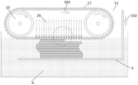
Fig. 1 is a schematic structural diagram of embodiment 1 of the present invention.
Fig. 2 is a schematic top view of the structure of fig. 1.
FIG. 3 is a schematic sectional view A-A of FIG. 1.
Fig. 4 is a schematic structural diagram (state one) of embodiment 2 of the present invention.
Fig. 5 is a schematic structural diagram (state two) of embodiment 2 of the present invention.
Fig. 6 is a schematic structural diagram (state one) of embodiment 3 of the present invention.
Fig. 7 is a schematic structural diagram (state two) of embodiment 3 of the present invention.
Fig. 8 is a schematic structural diagram of embodiment 4 of the present invention.
Fig. 9a is a schematic structural diagram of embodiment 5 of the present invention.
FIG. 9b is a schematic sectional view A-A of FIG. 9 a.
Fig. 10 is a schematic structural diagram of embodiment 6 of the present invention.
Fig. 11 is a schematic structural diagram of embodiment 7 of the present invention.
Fig. 12 is a schematic structural diagram of embodiment 8 of the present invention.
Fig. 13 is a schematic structural diagram of embodiment 9 of the present invention.
Fig. 14 is a schematic structural diagram of embodiment 10 of the present invention.
Fig. 15 is a schematic structural diagram of embodiment 11 of the present invention.
Fig. 16 is a schematic structural diagram (state one) of embodiment 12 of the present invention.
Fig. 17 is a schematic structural diagram (state two) of embodiment 12 of the present invention.
Fig. 18 is a schematic structural view of embodiment 13 of the present invention.
Fig. 19 is a schematic structural diagram of embodiment 14 of the present invention.
Fig. 20 is a schematic structural view of embodiment 15 of the present invention.
Fig. 21 is a partially enlarged schematic view of fig. 20.
Detailed Description
The invention will be further illustrated with reference to the following specific examples. It should be understood that these examples are for illustrative purposes only and are not intended to limit the scope of the present invention. Further, it should be understood that various changes or modifications of the present invention may be made by those skilled in the art after reading the teaching of the present invention, and such equivalents may fall within the scope of the present invention as defined in the appended claims.
Example 1
A photocuring 3D printing system as shown in fig. 1 includes a material carrier 3 and a spreader 11. Wherein the spreader 11 comprises a turning belt 17 and a turning roller group, the turning roller group (at least comprising two turning rollers) comprises turning rollers 15-1 and 15-2, the turning belt 17 is supported by the turning roller group and rotates along an arrow 103 along with the rotation of the turning roller group. At least a partial area of the spreading side of the spreader 11 is the light-transmitting area 12, where the spreading side refers to the side of the spreader 11 opposite to the material carrier 3, i.e. the bottom of the rotating belt 17 shown in fig. 1, and the specific position of the rotating belt 17 corresponding to the spreading side is dynamically changed along with the rotation of the rotating belt 17. The light-transmitting area 12 is disposed on the rotating belt 17, for example, the rotating belt 17 may be transparent, that is, the rotating belt 17 may be made of a light-transmitting material, and the light beam 29 irradiates the printing material in a pressed state through the rotating belt 17 to form the cured layer 41. In order to reduce the deformation of the rotating belt 17 and to improve the thickness accuracy of the spreading layer, the spreader 11 may further include a transparent platen 16, and the transparent platen 16 may transmit light, for example, a light beam 29, through the transparent platen 16 and the rotating belt 17 to irradiate the photosensitive printing material layer. It is also possible to provide a release layer 46 on the surface of the rotating belt 17 to further increase the speed of separation of the rotating belt 17 from the solidified layer 41. For example, an applicator 70 may be further provided to apply a lubricating layer to the surface of the rotating belt 17, or the applicator 70 may permeate a polymerization inhibitor (e.g., oxygen) into the rotating belt 17 so that the rotating belt 17 can be more easily separated from the cured layer 41.
Referring to fig. 1, the light-transmitting area 12 is an area of a flat portion of the side of the transfer belt 17 facing the carrier 3, for example, the endless transfer belt 17 may be transparent, and the light beam 29 irradiates the photosensitive printing material 4 in a pressed state below the transfer belt 17 through the transfer belt 17 to form a cured layer 41. Relative translational and vertical movements between the tripper 11 and the material carriers 3 are possible, for example a movement of the material carriers 3 along the first arrow 101 or a movement of the tripper 11 in the direction opposite to the first arrow 101 effects a relative translational movement between the tripper 11 and the material carriers 3, and a movement of the material carriers 3 along the second arrow 102 or a movement of the tripper 11 in the direction opposite to the second arrow 102 effects a relative vertical movement between the tripper 11 and the material carriers 3. The relative translational movement between the spreader 11 and the carrier 3 deposits the print 4 between the spreader 11 and the carrier 3, and the light beam 29 irradiates the print between the spreader 11 and the carrier 3 through the transfer belt 17 (i.e. through the light-transmitting zone 12 on the transfer belt 17) to form a solidified layer 41. After each layer is printed, the spreader 11 and the material carrier 3 are moved vertically by a set distance, for example, the material carrier 3 is moved by a layer thickness along the second arrow 102, and then the spreader 11 and the material carrier 3 can be moved in a reverse relative translational motion, for example, the material carrier 3 is moved in a reverse direction along the first arrow 101, and simultaneously the spreader 11 is rotated in a reverse direction along the third arrow 103, so that the next layer of printing material is spread and solidified, and the layers are stacked until the solidified mould 5 is printed. After the curing layer 41 is formed by laying and photocuring by the rotating belt type material laying device 11, the curing layer 41 is more favorably separated from the rotating belt 17, and meanwhile, the light-transmitting area 12 with a larger area can be arranged, so that the curing speed is favorably increased.
In addition, a separation layer 46 (not shown in the figure) can be arranged on the surface of the rotating belt 17, and the separation layer 46 is positioned between the rotating belt 17 and the solidified layer 41, so that the separation speed of the rotating belt 17 and the solidified layer 41 is further improved. For example, an applicator 70 may be further provided, and a lubricating layer forming spacer 46 may be applied to the surface of the rotating belt 17; alternatively, the transfer belt 17 provided with the separation layer 46 can be more easily separated from the cured layer 41 by permeating a polymerization inhibitor (e.g., oxygen) into the transfer belt 17 through the applicator 70 so that a layer of the photosensitive print material 4 adjacent to the transfer belt 17 is irradiated with the light beam 29 without being cured by absorbing oxygen to form the separation layer 46. In order to reduce the deformation of the rotary belt 17 and improve the accuracy of the thickness of the paving layer in some embodiments, the paving machine 11 may further comprise a transparent pressing plate 16, and the transparent pressing plate 16 is attached to the inner side surface of the paving side of the rotary belt 17 for reducing the deformation of the paving side of the rotary belt 17. The transparent platen 16 may be transparent, for example, a light beam 29 may illuminate the photosensitive print layer through the transparent platen 16 and the rotating belt 17. Transparent platen 16 is not required for the present invention, and in addition, the transmissive region 12, transparent platen 16, and the projected area of illumination of beam 29 generally correspond.
Fig. 2 illustrates the top view of fig. 1 and shows only the positional relationship between the light-transmitting areas 12, the charge carrier 3 and the curing mold 5 for ease of illustration. The dashed and dotted lines show the outline pattern of the respective layer of the cured model 5, and when the spreader 11 is moved along the first arrow 101, the spreader 11 will spread the photosensitive printing material 4 onto the carrier 3, while the transparent area 12 is also moved along the first arrow 101, and the beam is irradiated when the transparent area 12 is moved to the irradiation region 26 overlapping the layer outline pattern projection of the cured model 5, as indicated by the cross-hatching in the figure. Due to the adoption of the rotary belt type structure, the larger light transmission area 12 is provided, the larger irradiation area 26 can be realized, and the printing speed can be greatly improved. In addition, by regulating and controlling the rotating speed of the rotating belt 17 and the horizontal moving speed of the material spreader 11 relative to the material carrier 3, the rotating belt 17 and the material carrier 3 or the curing model 5 on the material carrier 3 can keep pure rolling, and the rotating belt 17 and the curing layer 41 of 41 can not slide, so that the precise positioning of the curing layer 41 can be promoted, and the printing precision is promoted.
Fig. 3 is a sectional view of the direction a-a of fig. 1, and further illustrates a light source system, the light source 2 may be disposed outside the rotating belt 17, and a reflector 85 is disposed inside the rotating belt 17 to reflect the light beam 29 emitted from the light source 2 toward the material carrier 3 for selectively irradiating the cured layer 41. Such structure does benefit to the arrangement and the lectotype of light source 2 more, also makes things convenient for the heat dissipation of light source 2, also does benefit to and reduces the space that changes area 17 and encircle the envelope, does benefit to the length that reduces and changes area 17, does benefit to the life-span and the reduce cost that promote and change area 17.
In a preferred embodiment of the invention, the rotational speed of the spreader 11 is adapted to the relative speed of movement of the material carriers 3 in such a way that the rotating belt 17 of the spreader 11 essentially does not slip with the material carriers 3, but merely rolls, so that the arrangement ensures precise positioning of the layer of spread material applied to the material carriers 3.
Example 2
Referring to fig. 4 and 5, auxiliary scrapers 13 are arranged on both left and right sides of the spreader 11, and which auxiliary spreader 13 operates is determined according to the relative horizontal movement direction of the material carriers 3 and the spreader 11, so that spreading and solidification can be achieved during bidirectional movement. For example, in fig. 4, the carrier 3 moves along the first arrow 101, or the rotary drum moves along the direction opposite to the first arrow 101, the spreader 11 rotates along the third arrow 103 (i.e. the rotary belt 17 rotates along the third arrow 103), the auxiliary scraper 13-2 operates to form the preprinted material layer 42 on the left side of the spreader 11, the preprinted material layer 42 is laid on the carrier 3 through the spreader 11, and the cured layer 41 is formed by irradiation and curing of the light beam 29. When one layer is printed, the material carrier 3 moves downwards along the second arrow 102 by a set distance, such as the thickness of one spreading layer, and then the next layer is printed by moving along the direction of the first arrow 101 as shown in fig. 5, or the rotary drum moves along the direction opposite to the first arrow 101, the spreader 11 rotates reversely, i.e. rotates along the third arrow 103 as shown in fig. 5, and at the same time, the auxiliary scraper 13-1 on the right side operates to form the preprinted material layer 42 on the right side of the spreader 11, and the preprinted material layer 42 is spread on the material carrier 3 by the spreader 11 and is solidified by being irradiated by the light beam 29 to form the solidified layer 41. This is repeated until the curing mold 5 is printed. Therefore, the material can be paved and printed in the reciprocating motion process of the material carrier 3, and the printing speed is improved. In addition, the auxiliary scraper 13 is also illustrated in fig. 4 and 5 in the form of a rotating roller, but of course other forms are possible, such as a scraper, which facilitates the control of the layer thickness of the preprinted material layer 42 by controlling the rotation of the auxiliary scraper 13 in the form of a rotating roller compared to a scraper. In addition, fig. 4 and 5 also illustrate the placement of the feeders 18, such as the right-hand feeder 18-1 and the left-hand feeder 18-2, which can work with the corresponding auxiliary runners 13.
In addition, fig. 5 also shows that the light source 2 is arranged above the material spreader 11, and the light beam emitted by the light source 2 irradiates the preprinted material layer 42 (i.e. the material layer) between the material spreader 11 and the material carrier 3 through the whole material spreader 11 to form a solidified layer 41. Because the light source 2 is arranged outside the spreading device 11, the arrangement and the type selection of the light source 2 are more convenient, and the heat dissipation of the light source 2 is also convenient. For example, by arranging the printing material recoverers 19 on the left and right sides of the light source 2, for example, arranging the printing material recoverer 19-1 on the right side of the light source 2 and the printing material recoverer 19-2 on the left side, the two printing material recoverers can work alternately when the spreader 11 operates in a reciprocating manner, so that the outer side of the spreader 11 can be ensured to be clean, and the phenomenon that the printing material driving the spreader 11 to the upper part of the rotating belt 17 in the drawing is solidified when the light beam 29 irradiates, and the subsequent spreading and accurate printing are influenced is avoided. Fig. 4 and 5 also illustrate that by forming the preprinting layer 42 on the spreader 11, the carrier 3 can be kept from being fully spread with printing material, the application of printing material during printing can be reduced, the structure can be simplified, and the cost can be reduced.
Example 3
Fig. 6 and 7 illustrate that an imaging printhead, such as color jets 83 in fig. 6, may also be provided on spreader 11. Fig. 6 illustrates that a preprinted layer 42 is formed on the spreader 11 by the feeder 18-2 and the auxiliary scraper 13-2, and then pigment is sprayed onto the preprinted layer 42 on the spreader 11 by the color nozzle 83 to form an image-forming layer, specifically, the image-forming layer is color pigment, and the preprinted layer 42 is brought to a position between the spreader 11 and the material carrier 3 along with the rotation of the spreader 11 and is irradiated by the light beam 29 to form a cured layer 41, which is cured layer by layer to form a color model or a cured model with a three-dimensional pattern. Fig. 7 shows that the color nozzle 83 first sprays the color onto the spreader 11, and then continues to form a preprinted material layer 42 on the spreader 11 by means of the feeder 18-1 and an auxiliary scraper 13-1 downstream of the feeder 18-1, the preprinted material layer 42 is covered with the color, and is brought to a position between the spreader 11 and the material carrier 3 with the rotation of the spreader 11 to be irradiated by the light beam 29 to form a solidified layer 41, which is solidified layer by layer to form a color pattern or a solidified pattern having a three-dimensional pattern. Compared with the embodiment shown in fig. 8 in which the color nozzle 83 and the spreader 11 are separately disposed, the present embodiment can reduce the occupation of the left and right space of the spreader 11, and is beneficial to reducing the stroke of the printhead moving in the left and right directions, and the color pigment and the preprinting material layer 42 are combined in advance, and meanwhile, the spreading and curing are beneficial to improving the printing speed of the color curing model.
Fig. 6 and 7 also show that the left and right outer sides of the spreader 11 can be respectively provided with a printing material recoverer 19, such as a right printing material recoverer 19-1 and a left printing material recoverer 19-2, so that the excess photosensitive printing material 4 which is laid on the material carrier 3 or the curing model 5 but is not cured can be conveniently recovered, the cleanness of the printing process is kept, the precision of the model is improved, and a large amount of printing material is not laid on the material carrier 3, so that the use amount of the printing material can be saved, and the application cost is reduced. The printing material recoverer 19 may employ a vacuum suction device or other device capable of recovering the printing material in a fluid state.
Example 4
Fig. 8 shows that the color nozzles 83 may be disposed on both left and right outer sides of the spreader 11, or at least one outer side of the spreader 11 may be disposed with the color nozzles 83, so that the spreader 11 may reciprocate left and right to perform color printing synchronously. For example, in fig. 8, the spreader 11 moves along a first arrow 101, the rotating belt 17 rotates along a third arrow 103, the feeder 18 spreads the pre-printed material layer 42 with a set thickness on the spreader 11 by the scraper 13-1, and the pre-printed material layer is spread between the carrier 3 and the spreader 11 by the spreader 11 and solidified by the irradiation of the light beam 29 to form the solidified layer 41. Then, the unnecessary photosensitive printing material 4 which is not cured is recovered by the printing material recoverer 19-2, and then the color head 83-2 ejects the pigment to the surface of the cured layer 41 to form color printing. Of course, it is also possible that the right color head 83-1 first ejects the pigment, then the spreader 11 further spreads the pre-print layer 42 and cures by the light beam 29 irradiating through the spreader 11 to form the cured layer 41, and then the excess photosensitive print 4 that is not cured is recovered by the print recoverer 19-2. By adopting the structure, a color model or printing with a pattern model can be formed, and the processes of spreading, curing, color printing and the like can be carried out simultaneously, so that the printing speed of the color model can be greatly improved.
The figure also shows that 4 rotating rollers 15 are adopted to support the rotating belt 17 to form the material spreading device 11, so that a larger internal space of the material spreading device 11 can be formed, internal devices are more convenient, such as the arrangement of the light source 2, the size in the left and right directions cannot be increased, the structure compactness of the material spreading device 11 is more convenient, if the rotating rollers 15 with smaller diameters are adopted, the area (the area of a plane area) of the light transmitting area 12 facing the direction of the material carrier 3 can be increased by the material spreading device 11 under the condition of the same left and right sizes, the structure compactness of the printing device is facilitated, the reduction of the left and right reciprocating motion stroke of the material spreading device 11 and the increase of the light beam irradiation area are also facilitated.
Example 5
Fig. 9a shows that the spreader 11 is arranged below the material carrier 3, the spreader 11 is arranged in a bin 68, the bin 68 stores the material liquid of the photosensitive printing material 4, the spreader 11 is partially immersed in the photosensitive printing material 4, the transfer belt 17 drives the photosensitive printing material 4 to form a preprinted material layer 42 on the outer side surface protruding above the liquid level of the photosensitive printing material 4 along with the rotation of the spreader 11, and drives the area between the material carrier 3 and the spreader 11, and the light beam 29 emitted by the light source 2 irradiates through the transfer belt 17 to form the cured layer 41. By adopting the structure, the rotary belt 17 can conveniently drive the photosensitive printing material 4 to form the preprinting material layer 42, and a feeder and an auxiliary scraper do not need to be separately arranged, so that the structure is simple. The spreader 11, bin 68 and light source 2 may constitute a print head. For example, the print head can be moved in the direction of a first arrow 101 to print a layer, the carrier 3 is moved in the direction of a second arrow 102 by a set distance, for example, the thickness of one layer of a paving layer, and the print head is then moved in the direction opposite to the second arrow 102 while the rotary belt 17 is rotated in the direction opposite to the third arrow 103 to print the next layer. And stacking and curing layer by layer until the curing model 5 is printed. This embodiment does benefit to the application that reduces the printing material more, and the pre-printed material layer 42 that does not have the solidification is taken back to the workbin 68 more easily, carries out along with changeing the belt 17 cyclic utilization, is difficult to drip on the material carrier 3, does benefit to practice thrift the printing material, and reduce cost keeps printing process's clean and tidy, is favorable to promoting the printing precision. The effect of using 4 turning rolls 15 in fig. 9a is similar to that of fig. 8 and will not be described in detail.
In order to prevent the photosensitive printing material 4 from entering the inside of the rotary belt 17 and being cured by the irradiation of the light beam 29 to affect the normal operation of the rotary belt 17, a vertical edge structure may be provided on the edges of both sides of the rotary belt 17, as shown in fig. 9 b. The vertical edge structure includes a first vertical edge 17-1 rising toward the inner side of the transfer belt 17, and the transfer belt 17 is partially immersed in the photosensitive printing material 4 without allowing the photosensitive printing material 4 to flow into the inside of the transfer belt 17. The vertical edge structure may further include a second vertical edge 17-2, the second vertical edge 17-2 is connected to the first vertical edge 17-1 and extends vertically to the outside of the rotating belt 17, and most preferably, the second vertical edge 17-2 does not protrude from the rotating belt 17, and an annular groove is formed between the first vertical edge 17-1 and the second vertical edge 17-2, so that the excess photosensitive printing material 4 can flow back into the bin 68 along the groove. The vertical edge structure can also improve the rigidity of the rotating belt 17, reduce the deformation of the rotating belt 17 and improve the printing precision.
Example 6
Fig. 10 illustrates a method of printing a pattern or color model that combines electromagnetic imaging technology with the spreader 11. The imaging printhead in this embodiment selectively attracts the developer 86 in the developer 78 to the developer drum 62 for the electromagnetic imaging printhead assembly 72 to rotate with the developer drum 62 to form an imaging layer, i.e., a developer layer 88, such as the developer layer 88-1 formed by the electromagnetic imaging printhead assembly 72-1 in the figure, onto the rotating belt 17, wherein the developer layer 88-1 is attracted to the pre-print layer 42 on the rotating belt 17, but the developer layer 88-1 may be attracted to the rotating belt 17 first and then the pre-print layer 42 is laid on the rotating belt 17. Multiple electromagnetic imaging printhead assemblies 72 may also be provided, such as electromagnetic imaging printhead assembly 72-2 further downstream from electromagnetic imaging printhead assembly 72-1, and the layer of developer material 88-2 also transferred to the belt 17, and multiple electromagnetic imaging printhead assemblies may be used to produce more color prints. The inner sides of the rotating belts 17 corresponding to the electromagnetic imaging print head assemblies 72 are respectively provided with a biasing device 36, the biasing device 36 has high voltage or magnetic field, and can attract the developing material layer 88 to the rotating belts 17, for example, the electromagnetic imaging print head assembly 72-1 is correspondingly provided with a biasing device 36-1, and the electromagnetic imaging print head assembly 72-2 is correspondingly provided with a biasing device 36-2. The figure also shows that an auxiliary roller 15a is arranged on the inner side of the rotating belt 17 corresponding to the auxiliary scraper 13, and the thickness of the preprinted material layer can be more accurately controlled by controlling the gap between the auxiliary scraper 13 and the auxiliary roller 15a, so that the printing precision is favorably improved.
Example 7
Fig. 11 illustrates an imaging printhead that includes a plurality of electromagnetic imaging printhead assemblies 72 arranged in synchronized engagement with a transport drum 92, i.e., the developer drum 62 and the transport drum 92 are both rotated synchronously and roll relative to each other to improve the accuracy of transfer of the developer layer 88. The developer layers 88 of each of the electromagnetic imaging printhead assemblies 72 are transferred in a matched position to a transfer drum 92, a composite developer layer of color is formed on the transfer drum 92 in accordance with the layer pattern of the pre-cured pattern, and the composite developer layer is transferred to the transfer belt 17 to form an image layer for color pattern printing. The adoption of the mode of the conveying drum 92 can realize the matching and laying of the developing material layers of different colors or materials of each layer more accurately, and because the position and the rotating speed between each developing drum 62 and the conveying drum 92 are easier to control accurately, more accurate layer color arrangement can be realized, and more accurate color model printing can be realized. Also shown in FIG. 11 is a conveyor biasing device 94 having a voltage or magnetic field disposed inside the conveyor drum 92 at a location corresponding to each developer drum 62 for attracting the corresponding layer of developer to the conveyor drum 92, such as conveyor biasing device 94-1 disposed corresponding to the electromagnetic imaging printhead assembly 72-1, conveyor biasing device 94-2 disposed corresponding to the electromagnetic imaging printhead assembly 72-2, and conveyor biasing device 94-3 disposed corresponding to the electromagnetic imaging printhead assembly 72-3. The inner side of the rotating belt 17 corresponding to the transfer drum 92 is provided with the biasing device 36, and it is also possible to make the biasing device 36 common to the rollers 15 supporting the rotating belt 17, for example, saving space and cost.
As shown in fig. 11, an additional solidifying device 22 may be further provided, and the additional solidifying device 22 may irradiate light or heat towards the material carrier 3 to further solidify the printing material layer already laid on the material carrier 3, so as to increase the printing speed, and also facilitate further fusion between the pigment and the solidified layer 41, for example, the added color particle pigment may be heated after the model is formed, and then the color particle pigment is better combined with the photosensitive resin after being melted. Of course, a print recoverer 19 (not shown) may also be provided between the additional solidifier 22 and the spreader 11.
Example 8
Fig. 12 shows that the spreader 11 can be formed by three rollers 15 supporting a rotating belt 17, forming a triangular spreader 11, the spreader 11 being shown below the material carriers 3, but it can also be above the material carriers 3. On the left and right sides of the spreader 11, a hopper 18 and an electromagnetic imaging printhead assembly 72 (i.e., an imaging printhead) may be disposed. The feeder 18 is shown to simultaneously function as an auxiliary scraper to form the preprinted material layer 42 on the rotating belt 17, although an auxiliary scraper 13 (not shown) may be provided downstream of the feeder 18. Such an arrangement is more advantageous for the compactness of the print head space, and the part of the spreader 11 away from the material carrier 3 can be reduced while ensuring a relatively large light-transmitting area 12, which is advantageous for the arrangement of other devices.
Fig. 11 and 12 also show that the material carrier 3 can be moved along the trajectory 109, so that the print head can be moved without it, simplifying the structure and control of the print head. Of course, each time the material carrier 3 is circulated along the path 109, the entire body is moved along the second arrow 102 by a predetermined distance, for example, by the thickness of one layer of the covering material. Or the print head is moved in the opposite direction along the track and can be moved in the opposite direction of the second arrow 102 for a set distance, for example a distance corresponding to the thickness of the spreading layer, for each cycle of movement. Of course, this movement of the material carrier 3 can also be used in other embodiments.
In the invention, an electrostatic imaging technology (xenograph), an ion injection imaging technology (ionograph) or a magnetic imaging technology (magnetic) is generally referred to as an electromagnetic imaging technology, and a device for realizing electromagnetic imaging is called an electromagnetic imaging printing head assembly. The following description will be made mainly of an electrostatic imaging technique (or called an electrophotographic technique) and refer to fig. 10 to 12:
1) in the charging process, the photosensitive developing drum 62 is rotated in the direction indicated by the arrow thereof, and the surface of the developing drum 62 is charged with a negative charge (or a positive charge) by the charger 74. The charger may be a corona wire, corotron, scorotron, charge roller, or other charging means.
2) In the exposure imaging process, the developing engine 76 performs selective scanning irradiation on the surface of the developing drum 62 while the developing drum rotates. The surface layer 66 of the developing drum 62 is attached with a photoconductive material, and has a high resistivity without being irradiated with light. When the resistivity is significantly reduced at the place irradiated with light, the surface charge is conducted through the conductive body 64 and disappears. The charges of the portions not illuminated remain unchanged, i.e., an electrostatic latent image is formed. The development engine 76 may use a laser beam or a led (light emitting diode), or other light source capable of selectively controlling the irradiation point to form a dot matrix bitmap on the surface of the development drum 62. The photoconductive material may employ selenium, cadmium sulfide, zinc oxide, Organic Photoconductor (OPC), amorphous silicon, zinc oxide, or the like.
For embodiments employing ion injection (ionograph), the charger 74 and the development engine 76 are replaced by devices that selectively deposit charge on the development drum surface layer 66. The developing engine 76 is an ion or charge injector, that is, while the developing drum 62 rotates, the developing engine 76 selectively injects ions into the surface layer 66 of the developing drum 62 according to the three-dimensional model information to form a charge deposit, and an electrostatic latent image is formed on the surface layer 66. The charger 4 can be omitted by adopting the ion injection mode, and the surface layer 66 does not need to adopt a light guide material, so that the structure is simplified.
3) The developing process, the process of forming a real image from the electrostatic latent image, is completed by using the principles of charge like repulsion and opposite attraction. The developer 78 contains a print material (i.e., developer 86) that is typically a powder material, such as a polymer or thermoplastic, that is negatively (or positively) charged by friction or other means. When the surface portion of the developing drum 62 bearing the electrostatic latent image is rotated to the developing device 78, the developing device 78 applies a negative (or positive) bias voltage to the portion (i.e., the portion of the electrostatic latent image) to which light is applied, since the negative charge is neutralized, so that the powder bearing the negative (or positive) charge on the developing device 78 jumps to the exposed area of the developing drum. The dark areas (unexposed areas) on the drum remain negatively (or positively) charged, repel negatively (or positively) charged powder, do not adhere, and form an image on the drum 62 where the image formed by the developer 86 is visible, i.e., form a developer layer 88. The developer layer 88 may be formed by using a portion of the developing drum 62 where electric charges are neutralized, or the developer layer 88 may be formed by using a portion of the developing drum 62 where electric charges are not neutralized.
4) The transfer process (i.e., the process of directly or indirectly transferring the developer layer 88 from the developer drum 62 to the spreader 11) is illustrated in fig. 7 in which the developer layer 88 is directly transferred to the spreader 11 by the developer drum 62, and fig. 8 in which the developer layer 88 is indirectly transferred to the spreader 11 via the transfer drum 92.
5) Further, in some embodiments, the electromagnetic imaging printhead assembly 72 may also include a cleaning process to clean the surface of the developer drum 62. The first cleaner 80 cleans the residual print material that is not completely transferred from the surface of the developer drum 62 so that there is a clean developer drum surface in the next print cycle.
6) Further, in some embodiments, the electromagnetic imaging printhead assembly 72 may also be configured to perform a de-charging process after the cleaning process and before the charging process. The charger 74 also functions to dissipate electricity when charging the developing drum. Preferably, however, a separate charge remover 82 may be provided to remove the charge from the developer drum 62 and then the charger 74 may charge the surface of the developer drum 62 with a layer of charge. Suitable devices for eliminating the electricity include an exposure device for exposing the developing drum to light, or a corona eliminating device for charging the developing drum with a reverse polarity to eliminate the residual charge on the developing drum, or a high voltage alternating current corotron (corotrons) and/or a scorotron (scorotron), a rotating dielectric roller with an electrical conductor inside and a high voltage alternating current, or a combination thereof.
For an electromagnetic imaging printhead assembly implemented using magnetic imaging technology (Magnetgraph), the basic process is similar to that described above, except that the developer drum 62 may be a magnetic drum, the surface layer 66 of the developer drum 62 is a magnetic material layer composed of a magnetic material, and the developer engine 76 is an imaging head, and the magnetic state of each point on the surface is selectively changed in the magnetic material layer according to three-dimensional model information, such as by creating an array of magnetized regions in the surface layer 66 of the magnetic material to form recording dots that form a latent magnetic image. When the developing drum 62 rotates to the developing device 78, the magnetic pigment 86 having magnetization in the developing device 78 is selectively attracted to the surface of the developing drum 62 according to the latent magnetic pattern, the pigment is attracted to the surface layer 66 of the developing drum 62, the developing layer 88 of the developed pattern is formed, and then, the pattern is transferred to the spreader 11. The function of the first cleaning device 80 is the same as described above. In some embodiments, a demagnetizer may be provided to restore the magnetic state of the surface layer 66 of the development drum 62 to the original state. The above process is then repeated with the periodic rotation of the developing drum until the pattern printing is completed. By using the magnetic imaging technique, the surface layer 66 of the magnetic drum (i.e., the developing drum 62) has high hardness and longer service life, and the magnetic recording dots have a permanent memory function, i.e., the magnetic latent image formed by the magnetic recording dots can be used repeatedly in a periodic manner, so that the charger 74 can be omitted, and the structure can be simplified.
Example 9
Fig. 13 illustrates a continuous printing mode, in which the rotating belt 17 rotates continuously along the third arrow 103, the continuous pre-printed material layer 42 is laid on the material carrier 3, the material carrier 3 moves continuously along the second arrow 102, the light beam 29 selectively irradiates the pre-printed material layer 42 through the light-transmitting area of the rotating belt 17 to form the solidified layer 41, and the solidified layer 41 is stacked layer by layer to form the solidified model 5. In order to prevent the solidified layer 41 from sticking to the rotating belt 17, a spacer layer 46 may be provided, the spacer layer 46 keeping the rotating belt 17 slidable with the solidified layer 41. The spacer layer 46 may be coated with a lubricant or inhibitor layer on the outer surface of the transfer belt 17 using the coating applicator 70 shown in fig. 1 so that the print material in the spacer layer 46 is not cured by the irradiation of the light beam 29. An inhibitor such as oxygen may be provided on the inner side of the transfer belt 17, and the transfer belt 17 may be provided with a semipermeable membrane which is permeable to the inhibitor such as oxygen so that a layer of the printing material contacting the outer surface of the transfer belt 17 is irradiated with 29 and is not cured. Because the rotating belt 17 rotates continuously, the material carrier 3 moves continuously, so that the layering of the cured layer 41 is more fine, the printing precision is improved, and in addition, the printing speed can be greatly improved because the material spreading device 11 does not need to move left and right in a reciprocating manner.
Example 10
The number of the spreaders 11 may be 1 or more, and referring to fig. 14, the plurality of spreaders 11 prints simultaneously, which may greatly increase the printing speed. Fig. 14 shows that two spreaders 11 print simultaneously, the spreader 11-1 is in front (or upstream) of the spreader 11-2 in the horizontal movement direction with respect to the material carriers 3, the height position of the spreader 11-1 is lower by one spreader layer thickness than the spreader 11-2, the spreader 11-1 and the light beam 29-1 form a solidified layer 41-1, the spreader 11-2 and the light beam 29-2 form a solidified layer 41-2, the solidified layer 41-2 is stacked on the solidified layer 41-1, and the solidified layers 41-1 and 41-2 print simultaneously. The feeders 18-1 and 18-2 may also be in communication with a source (not shown) and may also be provided with pumping devices and valves in the path of the printed material between the feeders and the source. Alternatively, the material carriers 3 can be moved along the first arrow 101, or the spreaders 11-1 and 11-2 can be moved in the opposite direction to the first arrow 101.
Example 11
Fig. 15 shows that at least two applicators 11 are operated simultaneously, each applicator 11 applying a different or different photosensitive printing material and simultaneously applying a matching application and a respective selective light curing of the same application layer to obtain a different or different cured layer 41. For example, the material A may be used for the part of the solidification mold 5-1 formed by the spreader 11-1. The material spreader 11-2 forms part of the curing mold 5-2, and the material B can be used for part of the curing mold 5-2. It is also possible to provide print recyclers 19-1, 19-2 and 19-3, wherein the print recycler 19-2 is provided between the spreader 11-1 and the spreader 11-2, or two print recyclers 19 may be provided between the spreader 11-1 and the spreader 11-2 to absorb the material a and the material B, respectively. The printing material recoverer 19 recovers the excess photosensitive printing material 4 which is not cured, for example, in a vacuum absorption mode, ensures accurate laying and curing of each material in the composite material printing process, avoids mixing of multiple materials by mistake, and realizes an accurate composite material curing model. The spreaders 11-1 and 11-2 and the print retrievers 19-1, 19-2 and 19-3 etc. can be moved synchronously along the first arrow 101. After printing one layer, the material carrier 3 can move a set distance along the second arrow 102, and the layer-by-layer printing is performed to enable the cured layers 41 of the composite material to be stacked and combined layer by layer to form the cured model 5 of the composite material.
Example 12
Fig. 16 and 17 illustrate that feeding pistons are provided on both left and right sides of the material carrier 3, and when one feeding piston is used for feeding and the other feeding piston is used for receiving an excess photosensitive printing material, the feeding pistons on both sides alternate back and forth. As shown in fig. 16, the spreader 11 is at the rightmost end, the right feeding piston 36 moves upwards to push out the photosensitive printing material 4, the spreader 11 starts moving leftwards to scrape the photosensitive printing material 4 leftwards to form a spreading layer to be spread on the material carrier 3, meanwhile, the spreading layer in a squeezing state below the transparent area is subjected to selective light curing according to the information of the curing model 5, the spreader 11 moves to the position of the left feeding piston 38, the left feeding piston 38 moves downwards to recycle the redundant printing material above the left feeding piston 38, and the spreader 11 moves to the leftmost end, as shown in fig. 17; then the left feeding piston 38 moves upwards to push out the photosensitive printing material 4, the material spreader 11 starts to move rightwards, the photosensitive printing material 4 is pushed rightwards to be spread on the material carrier 3, meanwhile, the material spreading layer in the extrusion state below the light-transmitting area is subjected to selective illumination curing according to the information of the curing model 5, the material spreader 11 moves to the position of the right feeding piston 36, the right feeding piston 36 moves downwards, the redundant printing materials are recovered to the position above the right feeding piston 36, and the material spreader 11 moves to the rightmost end, as shown in fig. 16; repeating the above steps until the curing model 5 is printed.
Example 13
Fig. 18 illustrates a vortex type photo-curing 3D printing system, in which a rotating belt 17 of a spreader 11 is supported by rollers 15-1 and 15-2 and driven to rotate circularly along an arrow 103, a molding surface of a material carrier 3 is a cylindrical surface and rotates along an arrow 101 direction, relative rotation between the spreader 11 and the material carrier 3 realizes relative translational motion between the spreader 11 and the material carrier 3, a pre-printing material layer 42 formed on the rotating belt 17 is laid on the material carrier 3 in a winding manner, and a light beam 29 selectively irradiates a photosensitive printing material 4 through the rotating belt 17 to form a curing layer 41 which is bonded to a curing model 5 on the material carrier 3 or the material carrier 3, and the curing layer 41 is stacked layer by layer to form a three-dimensional curing model 5. Optimally, the spreader 11 and the material carrier 3 are arranged in a synchronous matching manner, namely the rotation speed of the two is reasonably set so that the contact part between the two keeps pure rolling, the pre-printing material layer 42 or the curing layer 41 is prevented from being folded when being stacked on the material carrier 3, and accurate printing is ensured. When the three-dimensional model is printed, the material spreading device 11 and the material carrier 3 can intermittently perform relative vertical movement in the direction away from each other layer by layer according to the thickness of the material spreading side, and the material carrier 3 performs winding type material spreading and printing layer by layer; or the material spreader 11 and the material carrier 3 can continuously and relatively move vertically along the direction away from each other, so that continuous winding type material spreading and printing can be carried out on the material carrier 3, and the printing speed is increased. The embodiment can avoid the need of horizontal relative movement or horizontal reciprocating movement between the material spreading device 11 and the material carrier 3, is beneficial to the control of the system, increases the stability of the operation of the system, and is particularly suitable for printing parts with annular characteristics.
Of course, an imaging printhead 99 may also be provided as shown in FIG. 18 to form an imaging layer on the preprint layer 42, for example, the imaging printhead 99 may be the previously described color jet 83 or electromagnetic imaging printhead assembly 72, or may include several electromagnetic imaging printhead assemblies 72 and a rotatable transfer drum 92, and the imaging layer may be a color pigment, or developer layer 88, or a composite developer layer.
Example 14
Fig. 19 illustrates another vortex type photo-curing 3D printing system, which is different from fig. 18 in that fig. 19 illustrates that the rotating belt 17 can be supported by three rollers 15-1, 15-2 and 15-3 to form a triangular arrangement, the rotating belt 17 is pressed to the material carrier 3 by the roller 15-1, the molding surface of the material carrier 3 is a cylindrical surface, the rotating belt 17 is driven to rotate circularly along an arrow 103, and the roller 15-1 corresponding to the spreading side of the spreader 11 is a light-permeable structure, so as to ensure smooth transmission of the light beam 29 for selective illumination. The embodiment is not only convenient for arranging devices, but also is more beneficial to the separation of the solidified layer 41 and the rotating belt 17 because the rotating belt 17 generates sudden change along the rotating direction of the roller 15-1 after the printing material is paved on the material carrier 3.
Example 15
Fig. 20 and 21 illustrate a photo-curing 3D printing system capable of continuous printing, which is different from the embodiment shown in fig. 13 in that the outer side surface of the rotating belt 17 is provided with a circumferentially arranged tooth structure, that is, a continuous interval arrangement of tooth convex surfaces 17b and tooth spaces 17a is formed along the outer side surface of the rotating belt 17 along the circumferential direction thereof, the tooth convex surfaces 17b and the tooth spaces 17a extend along the width direction of the width of the rotating belt 17, the tooth convex surfaces 17b are light-transmitting, and the tooth spaces 17a are light-proof structures, for example, a light-shielding layer is provided at the positions of the tooth spaces 17 a. The gullet 17a can carry photosensitive printing material 4, each of the tine structures forming a scraper that rotates with the rotation of the rotary belt 17 to cause relative translational movement of the rotary belt 17 (and the raised tine 17b and gullet 17a) with the carrier 3 to carry the photosensitive printing material 4 to the carrier 3, and the light beam 29 selectively irradiates the photosensitive printing material 4 through the raised tine 17b to form a cured layer 41. In this embodiment, since the photosensitive printing material 4 can be carried by the gullets 17a, relative translational movement between the spreader 11 and the material carrier 3 is not necessary, which further increases the printing speed and simplifies the system structure and control. The material carriers 3 can be moved continuously along arrow 102, for example with the rotation of the rotating belt 17 along arrow 103, avoiding a reciprocating movement of the spreader 11 or the material carriers 3, which further increases the printing speed. Of course, the above-described structure of the feeder 18 or the auxiliary scraper 13, or the structure of fig. 9a, etc. may be used in this embodiment, and it is not necessary to immerse the material carrier 3 or the curing mold 5 in the photosensitive printing material 4. Further, an image forming head 99 may be provided outside the circumferential surface of the belt 17 to print a color pattern or a composite pattern.
It should be noted that, in the present invention, the relative translational motion between the spreader 11 and the material carrier 3 may realize the laying of the photosensitive printing material 4 on the material carrier 3, that is, forming a laying layer, that is, the translational motion of the spreader 11 may be performed, the material carrier 3 is not moved, or the translational motion of the material carrier 3 may be performed, the spreader 11 is not moved, or the material carrier 3 and the spreader 11 are simultaneously moved in a translational motion, and the translational motion of the material carrier 3 or the spreader 11 refers to the movement along the direction of the first arrow 101 or the opposite direction in each figure, or the movement along the horizontal direction, or the movement along the direction parallel to the molding surface of the material carrier 3. The relative vertical movement between the spreader 11 and the material carrier 3 can realize the layer-by-layer stacking of the solidified layers 41 to form the solidified model 5 (i.e. a three-dimensional model, or a three-dimensional object), i.e. the spreader 11 can move vertically, the material carrier 3 is not moved, or the material carrier 3 moves vertically, the spreader 11 is not moved, or the material carrier 3 and the spreader 11 move vertically at the same time, and the vertical movement of the material carrier 3 or the spreader 11 refers to the movement along the direction of the second arrow 102 in the figure or the opposite direction, or the movement along the vertical direction, or the movement along the direction perpendicular to the molding surface of the material carrier 3. The forming surface of the carrier 3 refers to the surface of the carrier 3 that can receive the cured layer 41 or the preprinted layer 42.
In each embodiment, during the printing process, the rotation speed of the rotating belt 17 and the relative translation speed of the material carrier 3 and the printing head (for example, the speed of the printing head moving along the first arrow 101 in fig. 6) may be set to be reasonably matched, so that the rotating belt 17 and the material carrier 3 are purely rolled, a pre-printed material layer can be accurately laid on the material carrier 3, the printing precision is improved, friction between the rotating belt 17 and the material carrier 3 or a solidified printed material thereon is avoided, and the service life of the rotating belt is prolonged.
The printhead referred to above may include a spreader 11 and light source 2, may include a hopper 68, may include an auxiliary scraper 13, may include a hopper 18, may include a print recycler 19, may include a color nozzle 83, and may include an electromagnetic imaging printhead assembly 72. The light source 2 may or may not move with the spreader 1 or with the spreader 11.
The surface of the light-transmitting area 12 of the dispenser 11 on the side of the photosensitive printing material 4 (i.e., the surface facing the material support 3) in each embodiment may also be provided with a self-lubricating material such as polytetrafluoroethylene, or an oil-containing material to prevent the cured layer 41 from sticking to the light-transmitting area 12. The solidified layer 41 (solidified photosensitive printing material layer) can be quickly separated from the spreader 11, so that the printing speed is increased, and the printing precision is improved.
As shown in the foregoing embodiments, the light source 2 of the present invention may be DLP projection, or may be an LCD screen or LED array disposed on the transparent region of the spreader 11, or may be a laser source, which selectively irradiates the photosensitive printing material in the pressed state through a lens set by passing the laser through the transparent region 12 of the spreader 11, or other light sources capable of selectively irradiating.
The printing material 4 of the photo-curing printing device and the printing method of the invention can adopt liquid photosensitive resin material, can be any resin liquid which initiates polymerization reaction by illumination, can also be mixed liquid or slurry of photosensitive resin and other liquid or powder, such as ceramic powder, metal powder, plastic powder or other powder materials, and can also be mixed with cells, medicines, pigments and the like in the resin.
For the mixed slurry of the photosensitive resin and the metal powder or the ceramic powder, a green part (green part) can be manufactured by a 3D printing method according to the present invention in combination with a PIM method such as metal powder injection molding (MIM) or ceramic powder injection molding (CIM), and then degreased and sintered (Sintering) to form parts such as metal or ceramic. The photocuring printing device or the printing method can be used for quickly printing plastic or resin models and customizing metal or ceramic parts, biomedicine or other models more efficiently.
The description uses directional terms such as "above," "below," "left," "right," etc., for convenience in description based on the specific drawings, and not for limitation of the invention. In practical applications, the actual left or right position may differ from the drawings due to the spatial shift of the structure as a whole. But such variations are intended to be within the scope of the invention. While the above embodiments are optional embodiments of the present invention, those skilled in the art may make various changes or modifications without departing from the general concept of the present invention, and such changes or modifications should fall within the scope of the appended claims.
Claims (15)
1. The utility model provides a photocuring 3D printing system which characterized in that: the printing device comprises a material carrier (3) and a material spreading device (11), wherein the material spreading device (11) is of a belt-rotating type structure, the material spreading device (11) comprises a belt rotating (17) and a roller set, the belt rotating (17) is supported by the roller set and rotates along with the roller set, at least part of the material spreading side of the material spreading device (11) is a light-transmitting area (12), the light-transmitting area (12) is arranged on the belt rotating (17), the material spreading device (11) and a material carrying body (3) perform relative translational motion, a photosensitive printing material (4) is laid on the material carrying body (3) opposite to the light-transmitting area (12), and when the laid photosensitive printing material (4) is still in a squeezed state, a light beam (29) penetrates through the light-transmitting area (12) and selectively irradiates the photosensitive printing material (4) opposite to the light-transmitting area (12) to form a cured layer (41) according to-printed three-dimensional model information, the material spreading device (11) and the material carrier (3) can move vertically relative to each other, in the printing process, the distance between the material spreading device (11) and the material carrier (3) is enlarged, and the solidified layers (41) are stacked layer by layer on the material carrier (3) to form a solidified model.
2. The photocuring 3D printing system of claim 1, wherein: the spreading device (11) further comprises a transparent pressing plate (16), and the transparent pressing plate (16) is attached to the inner side face of the spreading side of the rotating belt (17) and used for reducing the deformation of the spreading side of the rotating belt (17).
3. The photocuring 3D printing system of claim 1, wherein: the photosensitive printing material pre-printing device is characterized by further comprising an auxiliary scraper (13) and an imaging printing head (99), wherein the auxiliary scraper (13) is arranged on the outer side of the material spreading device (11), so that a pre-printing material layer (42) is formed on the surface of the material spreading device (11) by the photosensitive printing material (4), then the pre-printing material layer is laid on the material carrier (3) through the material spreading device (11), and the imaging printing head (99) is arranged on the circumferential surface of the material spreading device (11) relatively and can form an imaging layer on the pre-printing material layer (42) through the imaging printing head (99).
4. A photocuring 3D printing system as recited in claim 3, wherein: the imaging printing head (99) is a color nozzle (83), the color nozzle (83) is arranged opposite to the circumferential surface of the material spreader (11) and can form an imaging layer of color pigment on the preprinting material layer (42) through the color nozzle (83).
5. A photocuring 3D printing system as recited in claim 3, wherein: the imaging printing head (99) is an electromagnetic imaging printing head assembly (72), the electromagnetic imaging printing head assembly (72) comprises a rotatable developing drum (62), the developing drum (62) is arranged relative to the circumferential surface of the material spreader (11), and an imaging layer formed by selective printing on the preprinting material layer (42) through the electromagnetic imaging printing head assembly (72) is a developing material layer (88).
6. A photocuring 3D printing system as recited in claim 3, wherein: the imaging printing head (99) comprises a plurality of electromagnetic imaging printing head assemblies (72) and a rotatable conveying drum (92), each electromagnetic imaging printing head assembly (72) comprises a rotatable developing drum (62) and a plurality of developing drums (62) which are arranged on the circumferential surface of the corresponding conveying drum (92), each conveying drum (92) is arranged on the circumferential surface of the corresponding material spreader (11), an imaging layer formed by selective printing on the surface of each conveying drum (92) through the plurality of electromagnetic imaging printing head assemblies (72) is a composite developing material layer, and the composite developing material layer is conveyed to the preprinting material layer (42) on the surface of the material spreader (11) and the material spreader (11) through the conveying drums (92) to be adsorbed and combined.
7. The photocuring 3D printing system of claim 1, wherein: the material spreading device further comprises a feeder (18), wherein the feeder (18) is arranged on the outer side of the peripheral surface of the material spreading device (11) or in front of the material carrier (3) in the relative translational motion direction.
8. The photocuring 3D printing system of claim 1, wherein: and the printing material recoverer (19) is used for absorbing the redundant photosensitive printing material (4) on the surface of the spreading device (11) or absorbing the redundant photosensitive printing material (4) on the surface of the curing layer (41).
9. The photocuring 3D printing system of claim 1, wherein: the photosensitive printing material spreading device is characterized in that the material spreading device (11) is partially immersed in the photosensitive printing material (4), vertical edge structures for preventing the photosensitive printing material (4) from flowing into the rotating belt (17) are respectively arranged at the edges of two sides of the rotating belt (17), a preprinting material layer (42) is formed at the outer side protruding out of the liquid level of the photosensitive printing material (4) through the rotation of the material spreading device (11), and the photosensitive printing material (4) is paved between the material spreading device (11) and the material carrying body (3).
10. A photocuring 3D printing system as recited in claim 8, wherein: at least two material spreading devices (11) work simultaneously, each material spreading device (11) is used for spreading light-sensitive printing materials (4) with different colors, and each material spreading device (11) simultaneously carries out matched material spreading and selective illumination curing on the same material spreading layer to obtain a cured layer (41) with different colors.
11. The photocuring 3D printing system of claim 1, wherein: at least two material spreading devices (11) work simultaneously, the positions of the material spreading directions of the adjacent material spreading devices (11) are different by the thickness of one material spreading layer, and each material spreading device (11) respectively and simultaneously carries out material spreading and selective illumination curing on different material spreading layers.
12. The photocuring 3D printing system of claim 1, wherein: and the opposite two sides of the material carrier (3) are respectively provided with feeding pistons which alternately ascend and descend in a reciprocating mode, and when the feeding piston at one side is used for feeding, the feeding piston at the other side is used for receiving redundant photosensitive printing materials (4).
13. The utility model provides a photocuring 3D printing system which characterized in that: the photosensitive printing material printing device comprises a material carrier (3) and a material spreading device (11), wherein the material carrier (3) is provided with a cylindrical forming surface and can rotate along the central axis of the cylindrical forming surface, the material spreading device (11) is of a belt-rotating structure, the material spreading device (11) comprises a belt rotating device (17) and a roller set, the belt rotating device (17) is supported by the roller set and rotates along with the roller set, at least part of the material spreading side of the material spreading device (11) is a light-transmitting area (12), the light-transmitting area (12) is arranged on the belt rotating device (17), relative rotation is carried out between the belt rotating device (17) and the material carrying body (3) of the material spreading device (11) to lay a photosensitive printing material (4) on the material carrying body (3) relative to the light-transmitting area (12), and when the laid photosensitive printing material (4) is still in a pressed state, a light beam (29) penetrates through the light-transmitting area (12) and selectively irradiates the photosensitive printing material (4) relative to the light-transmitting area (12) to form a cured layer (41) ) The material spreader (11) and the material carrier (3) can move vertically relative to each other, in the printing process, the distance between the material spreader (11) and the material carrier (3) is enlarged, and the solidified layers (41) are stacked layer by layer on the material carrier (3) to form a solidified model.
14. A photocuring 3D printing system as recited in claim 14, wherein: the rotating belt (17) of the material spreader (11) and the material carrying body (3) rotate relatively to spread the materials, and meanwhile, the material spreader (11) and the material carrying body (3) synchronously generate continuous relative vertical movement along the direction of mutual separation.
15. The utility model provides a photocuring 3D printing system which characterized in that: including material carrier (3) and spreading ware (11), spreading ware (11) are changeing the belt structure, spreading ware (11) are including changeing area (17) and roller set, it is by to change area (17) the roller set supports and rotates along with roller set, spreading ware (11) the side of spreading the material at least partial region be light-permeable zone (12), light-permeable zone (12) set up on changeing area (17), the lateral surface of changeing area (17) forms tooth structure of tooth's socket (17a) and tooth convex surface (17b) continuous interval arrangement along the circumferencial direction, tooth convex surface (17b) are light-permeable structure, tooth's socket (17a) are non-light-permeable structure, it is relative to lay photosensitive printing material (4) to light-permeable zone (12) through tooth's socket (17a) to change area (17) circulation rotation on carrying the material body (3), and the photosensitive printing material (4) of laying still are in when being in the extruded state, and a light beam (29) penetrates through the light-transmitting area (12) and selectively irradiates the photosensitive printing material (4) opposite to the light-transmitting area (12) according to the three-dimensional model information to be printed to form a solidified layer (41), the material spreading device (11) and the material carrier (3) can move vertically relative to each other, the distance between the material spreading device (11) and the material carrier (3) is enlarged during printing, and the solidified layer (41) is stacked layer by layer on the material carrier (3) to form a solidified model.
Applications Claiming Priority (2)
| Application Number | Priority Date | Filing Date | Title |
|---|---|---|---|
| CN201811619829.4A CN109605737A (en) | 2018-12-28 | 2018-12-28 | A kind of photocuring 3D printing system and Method of printing |
| CN2018116198294 | 2018-12-28 |
Publications (2)
| Publication Number | Publication Date |
|---|---|
| CN110901057A true CN110901057A (en) | 2020-03-24 |
| CN110901057B CN110901057B (en) | 2022-03-18 |
Family
ID=66012008
Family Applications (4)
| Application Number | Title | Priority Date | Filing Date |
|---|---|---|---|
| CN201811619829.4A Pending CN109605737A (en) | 2018-12-28 | 2018-12-28 | A kind of photocuring 3D printing system and Method of printing |
| CN201911348706.6A Active CN110884116B (en) | 2018-12-28 | 2019-12-24 | Photocuring 3D printing system and printing method |
| CN201911347069.0A Active CN110901057B (en) | 2018-12-28 | 2019-12-24 | Photocuring 3D printing system |
| CN201911347102.XA Active CN110901058B (en) | 2018-12-28 | 2019-12-24 | Photocuring 3D printing system and printing method |
Family Applications Before (2)
| Application Number | Title | Priority Date | Filing Date |
|---|---|---|---|
| CN201811619829.4A Pending CN109605737A (en) | 2018-12-28 | 2018-12-28 | A kind of photocuring 3D printing system and Method of printing |
| CN201911348706.6A Active CN110884116B (en) | 2018-12-28 | 2019-12-24 | Photocuring 3D printing system and printing method |
Family Applications After (1)
| Application Number | Title | Priority Date | Filing Date |
|---|---|---|---|
| CN201911347102.XA Active CN110901058B (en) | 2018-12-28 | 2019-12-24 | Photocuring 3D printing system and printing method |
Country Status (1)
| Country | Link |
|---|---|
| CN (4) | CN109605737A (en) |
Cited By (2)
| Publication number | Priority date | Publication date | Assignee | Title |
|---|---|---|---|---|
| CN113799312A (en) * | 2021-08-31 | 2021-12-17 | 上海翌上新能源科技有限公司 | Powder spreading device |
| CN114619667A (en) * | 2020-12-11 | 2022-06-14 | 中国科学院福建物质结构研究所 | Synchronous pushing and linear stripping device for printing ultrahigh-viscosity resin and resin preparation method |
Families Citing this family (11)
| Publication number | Priority date | Publication date | Assignee | Title |
|---|---|---|---|---|
| US12172370B2 (en) | 2019-05-23 | 2024-12-24 | General Electric Company | Recoat assemblies for additive manufacturing systems and methods for using the same |
| CN112813467B (en) * | 2019-11-15 | 2022-05-03 | 源秩科技(上海)有限公司 | Electrochemical machining apparatus and method thereof |
| CN113021892A (en) * | 2019-12-24 | 2021-06-25 | 源秩科技(上海)有限公司 | Photocuring printing system and method |
| CN112810140B (en) * | 2020-12-28 | 2023-03-10 | 上海联泰科技股份有限公司 | Data processing method, system, storage medium, 3D printing device and control method |
| CN115008748B (en) * | 2021-03-04 | 2024-02-13 | 源秩科技(上海)有限公司 | Photo-curing three-dimensional printing device and printing method |
| CN115431518A (en) * | 2021-06-01 | 2022-12-06 | 源秩科技(上海)有限公司 | Three-dimensional printing device and three-dimensional printing method |
| TWI815249B (en) * | 2021-12-17 | 2023-09-11 | 國立臺北科技大學 | Three-dimensional printing system and three-dimensional printing method |
| CN114850490B (en) * | 2022-03-31 | 2024-03-26 | 芯体素(杭州)科技发展有限公司 | Manufacturing method of electronic radiator based on 3D printing |
| CN115008739B (en) * | 2022-06-24 | 2023-09-01 | 东莞爱的合成材料科技有限公司 | Continuous printing method and device for three-dimensional object, electronic device and storage medium |
| CN115534307A (en) * | 2022-09-27 | 2022-12-30 | 湖南华曙高科技股份有限公司 | A kind of 3D printing method and 3D printing equipment of powder material |
| CN116175730B (en) * | 2023-03-23 | 2023-09-08 | 中国科学院空间应用工程与技术中心 | Improved method and device for roller scraper in photo-cured ceramic 3D printing spreading |
Citations (5)
| Publication number | Priority date | Publication date | Assignee | Title |
|---|---|---|---|---|
| CN103331911A (en) * | 2013-06-18 | 2013-10-02 | 珠海天威飞马打印耗材有限公司 | Rapid three-dimensional printing molding equipment and three-dimensional entity object molding method |
| CN204222195U (en) * | 2011-09-23 | 2015-03-25 | 斯特拉塔西斯公司 | For printing the accumulation manufacturing system of three-dimensional part |
| US20150131074A1 (en) * | 2012-06-04 | 2015-05-14 | Ivoclar Vivadent Ag | Method for the Construction of a Shaped Body |
| CN106003728A (en) * | 2016-06-28 | 2016-10-12 | 杭州铭展网络科技有限公司 | 3D printer for cylindrical wall forming |
| WO2016192626A1 (en) * | 2015-06-03 | 2016-12-08 | 珠海天威飞马打印耗材有限公司 | Three-dimensional rapid prototyping device and prototyping method |
Family Cites Families (13)
| Publication number | Priority date | Publication date | Assignee | Title |
|---|---|---|---|---|
| US9527244B2 (en) * | 2014-02-10 | 2016-12-27 | Global Filtration Systems | Apparatus and method for forming three-dimensional objects from solidifiable paste |
| BR112016029755A2 (en) * | 2014-06-23 | 2017-08-22 | Carbon Inc | methods of producing three-dimensional objects from materials having multiple hardening mechanisms |
| CN112549529B (en) * | 2014-07-13 | 2022-11-29 | 斯特拉塔西斯公司 | System for three-dimensional printing and method of manufacturing three-dimensional object |
| CN105711088B (en) * | 2014-12-02 | 2019-12-17 | 北京十维科技有限责任公司 | Photocuring 3D printer |
| CN105269816A (en) * | 2015-05-07 | 2016-01-27 | 南京百川行远激光科技有限公司 | Oxygen-obstructing light-permeating liquid scraping system |
| TWI566917B (en) * | 2015-06-15 | 2017-01-21 | 國立臺灣科技大學 | Light stereolithography apparatus and method |
| JP6772283B2 (en) * | 2015-11-13 | 2020-10-21 | パクシス リミティッド ライアビリティー カンパニー | Add-on manufacturing equipment, systems, and methods |
| CN105922587B (en) * | 2016-05-19 | 2019-02-01 | 深圳长朗智能科技有限公司 | A kind of continuous photocuring 3D printing equipment and its application method |
| CN106476267B (en) * | 2016-12-09 | 2018-11-20 | 深圳市鑫创盈科技有限公司 | The structure of light-sensitive material cured layer forming method and realization this method in 3D printing |
| JP6868406B2 (en) * | 2017-01-31 | 2021-05-12 | 株式会社ミマキエンジニアリング | Three-dimensional object modeling device |
| CN108927994A (en) * | 2017-05-22 | 2018-12-04 | 三纬国际立体列印科技股份有限公司 | Three-dimensional printing device |
| CN207789731U (en) * | 2017-12-04 | 2018-08-31 | 厦门光服科技有限公司 | A kind of 3D printing device |
| CN208277438U (en) * | 2018-05-17 | 2018-12-25 | 厦门艾斯美客科技有限公司 | A kind of photosensitive resin slot for continuous photocuring 3D printing |
-
2018
- 2018-12-28 CN CN201811619829.4A patent/CN109605737A/en active Pending
-
2019
- 2019-12-24 CN CN201911348706.6A patent/CN110884116B/en active Active
- 2019-12-24 CN CN201911347069.0A patent/CN110901057B/en active Active
- 2019-12-24 CN CN201911347102.XA patent/CN110901058B/en active Active
Patent Citations (5)
| Publication number | Priority date | Publication date | Assignee | Title |
|---|---|---|---|---|
| CN204222195U (en) * | 2011-09-23 | 2015-03-25 | 斯特拉塔西斯公司 | For printing the accumulation manufacturing system of three-dimensional part |
| US20150131074A1 (en) * | 2012-06-04 | 2015-05-14 | Ivoclar Vivadent Ag | Method for the Construction of a Shaped Body |
| CN103331911A (en) * | 2013-06-18 | 2013-10-02 | 珠海天威飞马打印耗材有限公司 | Rapid three-dimensional printing molding equipment and three-dimensional entity object molding method |
| WO2016192626A1 (en) * | 2015-06-03 | 2016-12-08 | 珠海天威飞马打印耗材有限公司 | Three-dimensional rapid prototyping device and prototyping method |
| CN106003728A (en) * | 2016-06-28 | 2016-10-12 | 杭州铭展网络科技有限公司 | 3D printer for cylindrical wall forming |
Cited By (3)
| Publication number | Priority date | Publication date | Assignee | Title |
|---|---|---|---|---|
| CN114619667A (en) * | 2020-12-11 | 2022-06-14 | 中国科学院福建物质结构研究所 | Synchronous pushing and linear stripping device for printing ultrahigh-viscosity resin and resin preparation method |
| CN113799312A (en) * | 2021-08-31 | 2021-12-17 | 上海翌上新能源科技有限公司 | Powder spreading device |
| CN113799312B (en) * | 2021-08-31 | 2023-10-31 | 上海翌上新能源科技有限公司 | Powder spreading device |
Also Published As
| Publication number | Publication date |
|---|---|
| CN110901058A (en) | 2020-03-24 |
| CN110901057B (en) | 2022-03-18 |
| CN110884116A (en) | 2020-03-17 |
| CN110884116B (en) | 2021-10-19 |
| CN109605737A (en) | 2019-04-12 |
| CN110901058B (en) | 2021-11-16 |
Similar Documents
| Publication | Publication Date | Title |
|---|---|---|
| CN110901057B (en) | Photocuring 3D printing system | |
| US11590695B2 (en) | Photocuring printing system and method | |
| US9141015B2 (en) | Electrophotography-based additive manufacturing system with transfer-medium service loops | |
| US10272664B2 (en) | Fabrication of 3D objects via multiple build platforms | |
| US10144175B2 (en) | Electrophotography-based additive manufacturing with solvent-assisted planarization | |
| CN115104065A (en) | System and method for additive manufacturing of three-dimensional (3D) structures based on lithography | |
| CN102555450B (en) | Applying device and imaging device | |
| JP3242917B2 (en) | Liquid developer imaging device | |
| US7020420B2 (en) | Device and method for electrographically printing or copying using liquid inks | |
| US4761669A (en) | Highlight color printing | |
| KR20090024771A (en) | Printing method using electrophotography | |
| CN104890241A (en) | Three-dimensional rapid prototyping equipment and prototyping method | |
| US20170210070A1 (en) | Large format electrophotographic 3d printer | |
| US20250332785A1 (en) | Three-Dimensional Printing Apparatus and Three-Dimensional Printing Method | |
| EP0635766B1 (en) | A liquid development system | |
| CN109459921B (en) | Selective spreading device and spreading method | |
| CN115431520B (en) | Three-dimensional printing device and method | |
| CN109551756B (en) | Rotary drum imaging printing device and printing method | |
| US6876833B2 (en) | Device and method for cleaning and for regenerating an image carrier during electrographic printing or copying by using liquid ink | |
| JP2009537035A (en) | Use of powders to form images on objects, webs or sheets | |
| CN217258457U (en) | Surface projection 3D printing breadth expanding device | |
| CN204712469U (en) | Three-dimensional fast shaping equipment | |
| US6799009B2 (en) | Applicator element and method for electrographic printing or copying using liquid coloring agents | |
| US8665489B2 (en) | Laser printing process using light controlled wettability | |
| CN214645902U (en) | Double-tube type three-dimensional carbon powder laser printer |
Legal Events
| Date | Code | Title | Description |
|---|---|---|---|
| PB01 | Publication | ||
| PB01 | Publication | ||
| SE01 | Entry into force of request for substantive examination | ||
| SE01 | Entry into force of request for substantive examination | ||
| GR01 | Patent grant | ||
| GR01 | Patent grant |