CN110901081A - Iron part viscose section cutting machine - Google Patents
Iron part viscose section cutting machine Download PDFInfo
- Publication number
- CN110901081A CN110901081A CN201911271006.1A CN201911271006A CN110901081A CN 110901081 A CN110901081 A CN 110901081A CN 201911271006 A CN201911271006 A CN 201911271006A CN 110901081 A CN110901081 A CN 110901081A
- Authority
- CN
- China
- Prior art keywords
- module
- product
- linear motion
- feeding
- cutter
- Prior art date
- Legal status (The legal status is an assumption and is not a legal conclusion. Google has not performed a legal analysis and makes no representation as to the accuracy of the status listed.)
- Pending
Links
Images


Classifications
-
- B—PERFORMING OPERATIONS; TRANSPORTING
- B29—WORKING OF PLASTICS; WORKING OF SUBSTANCES IN A PLASTIC STATE IN GENERAL
- B29C—SHAPING OR JOINING OF PLASTICS; SHAPING OF MATERIAL IN A PLASTIC STATE, NOT OTHERWISE PROVIDED FOR; AFTER-TREATMENT OF THE SHAPED PRODUCTS, e.g. REPAIRING
- B29C65/00—Joining or sealing of preformed parts, e.g. welding of plastics materials; Apparatus therefor
- B29C65/48—Joining or sealing of preformed parts, e.g. welding of plastics materials; Apparatus therefor using adhesives, i.e. using supplementary joining material; solvent bonding
-
- B—PERFORMING OPERATIONS; TRANSPORTING
- B29—WORKING OF PLASTICS; WORKING OF SUBSTANCES IN A PLASTIC STATE IN GENERAL
- B29C—SHAPING OR JOINING OF PLASTICS; SHAPING OF MATERIAL IN A PLASTIC STATE, NOT OTHERWISE PROVIDED FOR; AFTER-TREATMENT OF THE SHAPED PRODUCTS, e.g. REPAIRING
- B29C65/00—Joining or sealing of preformed parts, e.g. welding of plastics materials; Apparatus therefor
- B29C65/74—Joining or sealing of preformed parts, e.g. welding of plastics materials; Apparatus therefor by welding and severing, or by joining and severing, the severing being performed in the area to be joined, next to the area to be joined, in the joint area or next to the joint area
-
- B—PERFORMING OPERATIONS; TRANSPORTING
- B29—WORKING OF PLASTICS; WORKING OF SUBSTANCES IN A PLASTIC STATE IN GENERAL
- B29C—SHAPING OR JOINING OF PLASTICS; SHAPING OF MATERIAL IN A PLASTIC STATE, NOT OTHERWISE PROVIDED FOR; AFTER-TREATMENT OF THE SHAPED PRODUCTS, e.g. REPAIRING
- B29C65/00—Joining or sealing of preformed parts, e.g. welding of plastics materials; Apparatus therefor
- B29C65/78—Means for handling the parts to be joined, e.g. for making containers or hollow articles, e.g. means for handling sheets, plates, web-like materials, tubular articles, hollow articles or elements to be joined therewith; Means for discharging the joined articles from the joining apparatus
- B29C65/7802—Positioning the parts to be joined, e.g. aligning, indexing or centring
- B29C65/7805—Positioning the parts to be joined, e.g. aligning, indexing or centring the parts to be joined comprising positioning features
-
- B—PERFORMING OPERATIONS; TRANSPORTING
- B29—WORKING OF PLASTICS; WORKING OF SUBSTANCES IN A PLASTIC STATE IN GENERAL
- B29C—SHAPING OR JOINING OF PLASTICS; SHAPING OF MATERIAL IN A PLASTIC STATE, NOT OTHERWISE PROVIDED FOR; AFTER-TREATMENT OF THE SHAPED PRODUCTS, e.g. REPAIRING
- B29C65/00—Joining or sealing of preformed parts, e.g. welding of plastics materials; Apparatus therefor
- B29C65/78—Means for handling the parts to be joined, e.g. for making containers or hollow articles, e.g. means for handling sheets, plates, web-like materials, tubular articles, hollow articles or elements to be joined therewith; Means for discharging the joined articles from the joining apparatus
- B29C65/7841—Holding or clamping means for handling purposes
- B29C65/7847—Holding or clamping means for handling purposes using vacuum to hold at least one of the parts to be joined
-
- B—PERFORMING OPERATIONS; TRANSPORTING
- B29—WORKING OF PLASTICS; WORKING OF SUBSTANCES IN A PLASTIC STATE IN GENERAL
- B29C—SHAPING OR JOINING OF PLASTICS; SHAPING OF MATERIAL IN A PLASTIC STATE, NOT OTHERWISE PROVIDED FOR; AFTER-TREATMENT OF THE SHAPED PRODUCTS, e.g. REPAIRING
- B29C65/00—Joining or sealing of preformed parts, e.g. welding of plastics materials; Apparatus therefor
- B29C65/78—Means for handling the parts to be joined, e.g. for making containers or hollow articles, e.g. means for handling sheets, plates, web-like materials, tubular articles, hollow articles or elements to be joined therewith; Means for discharging the joined articles from the joining apparatus
- B29C65/7841—Holding or clamping means for handling purposes
- B29C65/785—Holding or clamping means for handling purposes using magnetic forces to hold at least one of the parts to be joined
-
- B—PERFORMING OPERATIONS; TRANSPORTING
- B29—WORKING OF PLASTICS; WORKING OF SUBSTANCES IN A PLASTIC STATE IN GENERAL
- B29C—SHAPING OR JOINING OF PLASTICS; SHAPING OF MATERIAL IN A PLASTIC STATE, NOT OTHERWISE PROVIDED FOR; AFTER-TREATMENT OF THE SHAPED PRODUCTS, e.g. REPAIRING
- B29C65/00—Joining or sealing of preformed parts, e.g. welding of plastics materials; Apparatus therefor
- B29C65/78—Means for handling the parts to be joined, e.g. for making containers or hollow articles, e.g. means for handling sheets, plates, web-like materials, tubular articles, hollow articles or elements to be joined therewith; Means for discharging the joined articles from the joining apparatus
- B29C65/7855—Provisory fixing
-
- B—PERFORMING OPERATIONS; TRANSPORTING
- B29—WORKING OF PLASTICS; WORKING OF SUBSTANCES IN A PLASTIC STATE IN GENERAL
- B29C—SHAPING OR JOINING OF PLASTICS; SHAPING OF MATERIAL IN A PLASTIC STATE, NOT OTHERWISE PROVIDED FOR; AFTER-TREATMENT OF THE SHAPED PRODUCTS, e.g. REPAIRING
- B29C65/00—Joining or sealing of preformed parts, e.g. welding of plastics materials; Apparatus therefor
- B29C65/78—Means for handling the parts to be joined, e.g. for making containers or hollow articles, e.g. means for handling sheets, plates, web-like materials, tubular articles, hollow articles or elements to be joined therewith; Means for discharging the joined articles from the joining apparatus
- B29C65/7858—Means for handling the parts to be joined, e.g. for making containers or hollow articles, e.g. means for handling sheets, plates, web-like materials, tubular articles, hollow articles or elements to be joined therewith; Means for discharging the joined articles from the joining apparatus characterised by the feeding movement of the parts to be joined
-
- B—PERFORMING OPERATIONS; TRANSPORTING
- B29—WORKING OF PLASTICS; WORKING OF SUBSTANCES IN A PLASTIC STATE IN GENERAL
- B29C—SHAPING OR JOINING OF PLASTICS; SHAPING OF MATERIAL IN A PLASTIC STATE, NOT OTHERWISE PROVIDED FOR; AFTER-TREATMENT OF THE SHAPED PRODUCTS, e.g. REPAIRING
- B29C66/00—General aspects of processes or apparatus for joining preformed parts
- B29C66/40—General aspects of joining substantially flat articles, e.g. plates, sheets or web-like materials; Making flat seams in tubular or hollow articles; Joining single elements to substantially flat surfaces
- B29C66/47—Joining single elements to sheets, plates or other substantially flat surfaces
- B29C66/472—Joining single elements to sheets, plates or other substantially flat surfaces said single elements being substantially flat
-
- B—PERFORMING OPERATIONS; TRANSPORTING
- B29—WORKING OF PLASTICS; WORKING OF SUBSTANCES IN A PLASTIC STATE IN GENERAL
- B29C—SHAPING OR JOINING OF PLASTICS; SHAPING OF MATERIAL IN A PLASTIC STATE, NOT OTHERWISE PROVIDED FOR; AFTER-TREATMENT OF THE SHAPED PRODUCTS, e.g. REPAIRING
- B29C66/00—General aspects of processes or apparatus for joining preformed parts
- B29C66/70—General aspects of processes or apparatus for joining preformed parts characterised by the composition, physical properties or the structure of the material of the parts to be joined; Joining with non-plastics material
- B29C66/74—Joining plastics material to non-plastics material
- B29C66/742—Joining plastics material to non-plastics material to metals or their alloys
- B29C66/7428—Transition metals or their alloys
- B29C66/74283—Iron or alloys of iron, e.g. steel
Landscapes
- Engineering & Computer Science (AREA)
- Mechanical Engineering (AREA)
- Chemical & Material Sciences (AREA)
- Crystallography & Structural Chemistry (AREA)
- Inorganic Chemistry (AREA)
- Adhesive Tape Dispensing Devices (AREA)
Abstract
The invention discloses an iron part adhesive section cutting machine, and aims to provide an iron part adhesive section cutting machine capable of improving production efficiency. The glue dispensing device comprises a machine table, wherein a glue dispensing module, a product taking module, a product feeding module, an adhesive tape taking module, an adhesive tape feeding module, a glue cutting module and a product glue dispensing moving module are arranged on the machine table, the product taking module and the product feeding module are in an X direction and are arranged side by side from left to right, the adhesive tape taking module and the adhesive tape feeding module are in an X direction and are arranged in front of the product taking module and the product feeding module side by side from left to right, the glue cutting module is arranged between the adhesive tape taking module and the adhesive tape feeding module in a matched mode, the product glue dispensing moving module is in a Y direction and is arranged on one side of the product taking module and the adhesive tape taking module in a matched mode, and the glue dispensing module is arranged on one side of. The invention is applied to the technical field of iron part viscose section cutting machines.
Description
Technical Field
The invention relates to a viscose section cutting machine for iron parts.
Background
In the printing or copying process of a printer or a copier, the carbon powder forms an image on the toner cartridge and is transferred onto the copy paper, a part of the carbon powder is left on the toner cartridge in the process, if the part is not removed, the carbon powder is transferred onto the next copy paper when the next copy paper is copied, the copying effect and the quality of the next copy paper are affected, at the moment, a scraper is needed to remove the carbon powder remained on the toner cartridge after the copier finishes copying one sheet, the scraper of the toner cartridge consists of a stainless steel knife and an adhesive tape adhered on the stainless steel knife, and the traditional technology needs to manually remove the adhesive tape, so that the production efficiency is low.
Disclosure of Invention
The invention aims to overcome the defects of the prior art and provides the iron part viscose section cutting machine capable of improving the production efficiency.
The technical scheme adopted by the invention is as follows: the glue dispensing device comprises a machine table, wherein a glue dispensing module, a product taking module, a product feeding module, a glue strip taking module, a glue strip feeding module, a glue cutting module and a product glue dispensing moving module are arranged on the machine table, the product taking module and the product feeding module are in an X direction and are arranged side by side from left to right, the glue strip taking module and the glue strip feeding module are in an X direction and are arranged in front of the product taking module and the product feeding module side by side from left to right, the glue cutting module is arranged between the glue strip taking module and the glue strip feeding module in a matching mode, the product glue dispensing moving module is in a Y direction and is arranged on one side of the product taking module and one side of the glue strip taking module in a matching mode, and the glue dispensing module is arranged on one side of the product glue dispensing moving module in a matching mode.
Further, the product point is glued and is removed the module and is included product point and glue mount, be provided with Y axle linear motion module on the product point is glued the mount, sliding fit has the point to glue on the Y axle linear motion module and removes the chassis, it places the board to be provided with the product on the removal chassis to glue, the product is placed and is provided with the spacing post of a plurality of on the board in the cooperation.
Further, the product taking module comprises a first fixing support, a first X-axis linear motion module in an X direction is arranged on the first fixing support, a first Z-axis linear motion module, a second Z-axis linear motion module and a third Z-axis linear motion module are sequentially arranged on the first X-axis linear motion module side by side, and the first Z-axis linear motion module, the second Z-axis linear motion module and the third Z-axis linear motion module are all matched with each other to form a magnetic suction module.
Furthermore, the adhesive tape taking module comprises an adhesive tape taking fixing frame, one end of the adhesive tape taking fixing frame is arranged at the tail end of the adhesive tape feeding module, a fourth Z-axis linear motion module and a second X-axis linear motion module in the X direction are arranged on the adhesive tape taking fixing frame, the fourth Z-axis linear motion module is located above the tail end of the adhesive tape feeding module, a fifth Z-axis motion module is arranged on the second X-axis linear motion module in a matched mode, and a sucker assembly is arranged on each of the fourth Z-axis linear motion module and the fifth Z-axis motion module.
Further, the glue cutting module comprises a cutter linear motion module, a cutter and a cutter cylinder, the cutter linear motion module is provided with a cutter moving seat in a matched mode, the cutter moving seat is provided with an arc-shaped groove, the cutter is provided with a sliding block matched with the arc-shaped groove, the cutter is arranged on the cutter moving seat, the sliding block is in sliding fit with the arc-shaped groove, one end of the cutter cylinder is hinged to the cutter moving seat, and the other end of the cutter cylinder is hinged to the sliding block.
Further, the cutter linear motion module includes first fixing base, second fixing base, third fixing base and linear motion cylinder, first fixing base reaches be provided with a plurality of slide bars between the second fixing base, the cutter removes a seat sliding fit and is in on the slide bar, the one end of linear motion cylinder articulates on the third fixing base, and the other end articulates the bottom that the seat was removed to the cutter, the inboard of first fixing base be provided with the cutter removes a seat complex buffer.
Further, the product material loading module includes material loading transmission module, the cooperation is provided with a plurality of panel beating on the material loading transmission module and places the subassembly, the panel beating is placed the subassembly and is included placing the bottom plate, it is provided with first panel beating locating part of matched with and second panel beating locating part on the bottom plate to place, first panel beating locating part reaches all the cooperation is provided with the stopper in the second panel beating locating part, it has the product spacing groove to open on the stopper.
Further, the first metal plate limiting part and the second metal plate limiting part all comprise a first limiting plate, a second limiting plate and a third limiting plate, the first limiting plate, the second limiting plate and the third limiting plate are perpendicularly arranged on the placing bottom plate, the first limiting plate and the second limiting plate are arranged in parallel, one end of the third limiting plate is arranged on one side of the first limiting plate, the other end of the third limiting plate is arranged on one side of the second limiting plate, a limiting groove is formed between the first limiting plate and the second limiting plate and between the third limiting plate, and the limiting blocks are arranged in the limiting groove in a matched mode.
Further, ironware viscose section cutter still include the material loading sensor, the material loading sensor sets up the end of material loading transmission module, and with the subassembly cooperation is placed to the panel beating.
Further, adhesive tape material loading module is including adhesive tape material loading fixing base, it has a plurality of to be X to leading to the groove to be provided with on the adhesive tape material loading fixing base to open, it is provided with the adhesive tape push pedal to lead to the groove, be provided with push pedal linear motion module in the adhesive tape material loading fixing base, push pedal linear motion module is located lead to the below of groove, and with adhesive tape push pedal fixed coordination mutually.
The invention has the beneficial effects that: compared with the prior art, in the invention, the product feeding die set is arranged on the stainless steel knife for feeding, the product taking module is arranged on the stainless steel knife at the tail end of the product feeding die set for taking materials and placing the materials on the product dispensing moving module, the adhesive tape feeding die set is arranged on the adhesive tape for feeding, the adhesive cutting module is arranged on the adhesive tape for cutting the tail end of the product feeding die set, the adhesive tape taking module is arranged on the adhesive tape for taking materials and placing the cut adhesive tape on the adhesive tape feeding die set on the product dispensing moving module, the product dispensing moving die set is arranged on the stainless steel knife and the adhesive tape and moving to the dispensing die set, the dispensing die set is arranged on the stainless steel knife for adhering the adhesive tape, and the production efficiency is improved through the dispensing die set, the product taking module and the adhesive tape taking module, The product feeding module, the adhesive tape taking module, the adhesive tape feeding module, the adhesive cutting module and the product dispensing moving module are arranged, so that the adhesive tape dispensing device has the advantage of improving the production efficiency, and the production efficiency can be improved.
Drawings
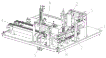
FIG. 1 is a schematic perspective view of a first aspect of the present invention;
FIG. 2 is a perspective view of the present invention from a second perspective;
FIG. 3 is a perspective view of a third aspect of the present invention;
FIG. 4 is a schematic perspective view of a product dispensing moving module;
FIG. 5 is a schematic perspective view of a product take-out module;
FIG. 6 is a schematic perspective view of the product pick-up module from another perspective;
FIG. 7 is a schematic perspective view of the adhesive tape feeding module and the adhesive tape reclaiming module;
FIG. 8 is a schematic perspective view of a glue cutting module;
FIG. 9 is a schematic perspective view of another view of the adhesive cutting module;
FIG. 10 is a schematic perspective view of a product loading module;
fig. 11 is a schematic perspective view of the first metal plate limiting member.
Detailed Description
As shown in fig. 1 to 11, in the present embodiment, the present invention includes a machine table 1, the machine table 1 is provided with a dispensing module 2, a product taking module 3, a product feeding module 4, an adhesive tape taking module 5, an adhesive tape feeding module 6, a adhesive cutting module 7 and a product dispensing moving module 8, the product taking module 3 and the product feeding module 4 are both in an X direction, the adhesive tape taking module 5 and the adhesive tape feeding module 6 are arranged side by side from left to right in the X direction and are arranged in front of the product taking module 3 and the product feeding module 4 from left to right side, the adhesive tape cutting module 7 is arranged between the adhesive tape taking module 5 and the adhesive tape feeding module 6 in a matching way, the product dispensing moving module 8 is Y-shaped and is arranged on one side of the product taking module 3 and the adhesive tape taking module 5 in a matching mode, and the dispensing module 2 is arranged on one side of the product dispensing moving module 8 in a matching mode. Compared with the prior art, in the present invention, the product feeding module 4 is configured to feed the stainless steel knife, the product taking module 3 is configured to take the stainless steel knife at the end of the product feeding module 4 and place the stainless steel knife on the product dispensing moving module 8, the adhesive tape feeding module 6 is configured to feed the adhesive tape, the adhesive cutting module 7 is configured to cut the adhesive tape at the end of the product feeding module 4, the adhesive tape taking module 5 is configured to take the cut adhesive tape from the adhesive tape feeding module 6 and place the cut adhesive tape on the dispensing product moving module 8, the product dispensing moving module 8 is configured to place the stainless steel knife and the adhesive tape and move the cut adhesive tape to the dispensing module 2, and the dispensing module 2 is configured to glue the adhesive tape on the stainless steel knife and pass through the dispensing module 2, The product taking module 3, the product feeding module 4, the adhesive tape taking module 5, the adhesive tape feeding module 6, the adhesive cutting module 7 and the product dispensing moving module 8 are arranged, so that the adhesive dispenser has the advantage of improving the production efficiency.
In this embodiment, the product dispensing moving module 8 includes a product dispensing fixing frame 801, a Y-axis linear motion module 802 is arranged on the product dispensing fixing frame 801, a dispensing moving chassis 803 is arranged on the Y-axis linear motion module 802 in a sliding fit manner, a product placing plate 804 is arranged on the dispensing moving chassis 803, and a plurality of limiting columns are arranged on the product placing plate 804 in a matching manner. The stainless steel knife is provided with a limiting hole matched with the limiting column, and the product placing plate 804 limits the stainless steel knife through the limiting column. During the use, the product placing plate 804 successively moves to the product is got the material module 3 and the adhesive tape is got the below of material module 5 for stainless steel sword and adhesive tape can be placed in proper order on the product placing plate 804.
In this embodiment, the product taking module 3 includes a first fixed bracket 301, a first X-axis linear motion module 302 in the X direction is provided on the first fixed bracket 301, a first Z-axis linear motion module 303, a second Z-axis linear motion module 304 and a third Z-axis linear motion module 305 are sequentially provided on the first X-axis linear motion module 302 side by side, and the first Z-axis linear motion module 303, the second Z-axis linear motion module 304 and the third Z-axis linear motion module 305 are all provided with a magnetic attraction module 306 in a matching manner. The magnetic module 306 is configured to absorb the stainless steel knife. Still be provided with the upset support on the third Z axle linear motion module 305, the upper end of upset support is articulated mutually with the one end of upset cylinder, the other end of upset cylinder with the third Z axle linear motion module 305 magnetism inhale the module 306 articulated mutually, third Z axle linear motion module 305 with magnetism inhale the module 306 articulated mutually, the upset support reaches the setting up of upset cylinder makes the third Z axle linear motion module 305 magnetism inhale the module 306 and can overturn it when absorbing the stainless steel sword.
In this embodiment, the adhesive tape taking module 5 includes an adhesive tape taking fixing frame 501, one end of the adhesive tape taking fixing frame 501 is disposed at the tail end of the adhesive tape feeding module 6, a fourth Z-axis linear motion module 502 and a second X-axis linear motion module 503 in the X direction are disposed on the adhesive tape taking fixing frame 501, the fourth Z-axis linear motion module 502 is located above the tail end of the adhesive tape feeding module 6, a fifth Z-axis motion module 504 is disposed on the second X-axis linear motion module 503 in a matching manner, and suction cup assemblies 505 are disposed on the fourth Z-axis linear motion module 502 and the fifth Z-axis motion module 504. The fourth Z-axis linear motion module 502 and the suction cup assembly 505 thereof are configured to press down the adhesive tape at the tail end of the adhesive tape feeding module 6, so as to facilitate the cutting of the adhesive tape cutting module 7, and the fifth Z-axis motion module 504 and the suction cup assembly 505 thereof are configured to suck and move the adhesive tape at the tail end of the adhesive tape feeding module 6.
In this embodiment, the glue cutting module 7 includes a cutter linear motion module 701, a cutter 702 and a cutter cylinder 703, the cutter linear motion module 701 is cooperatively provided with a cutter moving seat 704, an arc-shaped groove 705 is formed on the cutter moving seat 704, the cutter 702 is provided with a slider 706 adapted to the arc-shaped groove 705, the cutter 702 is disposed on the cutter moving seat 704, the slider 706 is slidably fitted in the arc-shaped groove 705, one end of the cutter cylinder 703 is hinged to the cutter moving seat 704, and the other end of the cutter cylinder 703 is hinged to the slider 706. In an initial state, the sliding block 706 is located in the middle of the arc-shaped groove 705, the cutter 702 is in a vertical state and cannot cut the adhesive tape, when the adhesive tape cutting machine is used, the cutter cylinder 703 pulls the cutter 702, so that the sliding block 706 slides to one end of the arc-shaped groove 705, the cutter 702 is in an inclined state at this time, the cutter linear motion module 701 further drives the cutter 702 to move, so that the cutter 702 can cut the adhesive tape, in the process, the angle of the cutter 702 can be adjusted by the cutter cylinder 703, so that the production cost can be well reduced, and when the cutter 702 is in the inclined state for cutting, the sliding block 706 abuts against one end of the arc-shaped groove 705, so that the cutter 702 is not easy to shake and can be easily cut.
In this embodiment, the cutter linear motion module 701 includes a first fixing seat 721, a second fixing seat 722, a third fixing seat 723 and a linear motion cylinder 724, a plurality of sliding rods 725 are disposed between the first fixing seat 721 and the second fixing seat 722, the cutter moving seat 704 is slidably fitted on the sliding rods 725, one end of the linear motion cylinder 724 is hinged to the third fixing seat 723, the other end is hinged to the bottom of the cutter moving seat 704, and a buffer 726 fitted with the cutter moving seat 704 is disposed inside the first fixing seat 721.
In this embodiment, the product feeding module 4 includes a feeding transmission module 401, the feeding transmission module 401 is provided with a plurality of sheet metal placing assemblies 402 in a matching manner, the sheet metal placing assemblies 402 include a placing bottom plate 403, a first sheet metal limiting part 404 and a second sheet metal limiting part 405 which are matched with each other are provided on the placing bottom plate 403, a limiting block 406 is provided in each of the first sheet metal limiting part 404 and the second sheet metal limiting part 405 in a matching manner, and a product limiting groove 407 is formed in the limiting block 406. The product limiting groove 407 is V-shaped.
In this embodiment, the first sheet metal limiting part 404 and the second sheet metal limiting part 405 both include a first limiting plate 411, a second limiting plate 412 and a third limiting plate 413, the first limiting plate 411, the second limiting plate 412 and the third limiting plate 413 are vertically disposed on the placing bottom plate 403, the first limiting plate 411 and the second limiting plate 412 are arranged in parallel, one end of the third limiting plate 413 is disposed on one side of the first limiting plate 411, the other end of the third limiting plate 413 is disposed on one side of the second limiting plate 412, a limiting groove is formed among the first limiting plate 411, the second limiting plate 412 and the third limiting plate 413, and the limiting block 406 is disposed in the limiting groove in a matching manner.
In this embodiment, ironware viscose section cutter still include the material loading sensor, the material loading sensor sets up the end of material loading transmission module 401, and with the subassembly 402 cooperation is placed to the panel beating. The feeding sensor is configured to sense whether a product is placed at the tail end of the feeding transmission module 401.
In this embodiment, adhesive tape feeding module 6 includes adhesive tape feeding fixing base 601, it has a plurality of to be X to leading to groove 602 to be provided with on the adhesive tape feeding fixing base 601, it is provided with adhesive tape push pedal 603 on leading to the groove 602, be provided with push pedal linear motion module 604 in the adhesive tape feeding fixing base 601, push pedal linear motion module 604 is located the below of leading to groove 602, and with adhesive tape push pedal 603 is fixed coordination mutually. The adhesive tape is placed at the front end of the adhesive tape push plate 603, and the adhesive tape push plate 603 is further driven by the push plate linear motion module 604 to make linear motion along the X direction, so that the adhesive tape push plate 603 pushes the adhesive tape to the tail end of the adhesive tape feeding fixing seat 601.
While the embodiments of the present invention have been described in terms of practical embodiments, they are not to be construed as limiting the meaning of the present invention, and modifications of the embodiments and combinations with other embodiments will be apparent to those skilled in the art in light of the present description.
Claims (10)
Priority Applications (1)
| Application Number | Priority Date | Filing Date | Title |
|---|---|---|---|
| CN201911271006.1A CN110901081A (en) | 2019-12-12 | 2019-12-12 | Iron part viscose section cutting machine |
Applications Claiming Priority (1)
| Application Number | Priority Date | Filing Date | Title |
|---|---|---|---|
| CN201911271006.1A CN110901081A (en) | 2019-12-12 | 2019-12-12 | Iron part viscose section cutting machine |
Publications (1)
| Publication Number | Publication Date |
|---|---|
| CN110901081A true CN110901081A (en) | 2020-03-24 |
Family
ID=69824881
Family Applications (1)
| Application Number | Title | Priority Date | Filing Date |
|---|---|---|---|
| CN201911271006.1A Pending CN110901081A (en) | 2019-12-12 | 2019-12-12 | Iron part viscose section cutting machine |
Country Status (1)
| Country | Link |
|---|---|
| CN (1) | CN110901081A (en) |
Citations (11)
| Publication number | Priority date | Publication date | Assignee | Title |
|---|---|---|---|---|
| CN105750473A (en) * | 2016-04-12 | 2016-07-13 | 深圳普迈仕精密制造技术开发有限公司 | Automatic ladder riveting and pressing production equipment |
| CN106298224A (en) * | 2016-09-29 | 2017-01-04 | 东莞市嘉龙海杰电子科技有限公司 | Transformer core adhesive tape and dispensing equipment |
| CN107651416A (en) * | 2017-09-15 | 2018-02-02 | 严传玉 | A kind of spot gluing equipment assembles charging & discharging machine |
| CN108930700A (en) * | 2018-09-05 | 2018-12-04 | 江苏铁锚明信交通科技有限公司 | Vehicle dormer window injection-molding edge ironware gasket automatic bonding equipment |
| CN108940741A (en) * | 2018-09-06 | 2018-12-07 | 广东立迪智能科技有限公司 | Full-automatic dispensing equipment for bracket lamp |
| CN109822923A (en) * | 2019-03-18 | 2019-05-31 | 苏州吉格尔科技有限公司 | An automatic/semi-automatic glue applicator |
| CN209578692U (en) * | 2018-12-05 | 2019-11-05 | 深圳润通智能科技有限公司 | A kind of novel sports mechanism |
| CN110437762A (en) * | 2019-07-17 | 2019-11-12 | 苏州微邦材料科技有限公司 | A kind of pressure sensitive conductive adhesive tape and its application in photovoltaic cell fitting |
| CN110919244A (en) * | 2019-12-12 | 2020-03-27 | 珠海市锦沣科技有限公司 | Automatic feeding welding machine |
| CN211806311U (en) * | 2019-12-12 | 2020-10-30 | 珠海市锦沣科技有限公司 | Rubber cutting mechanism |
| CN211807933U (en) * | 2019-12-12 | 2020-10-30 | 珠海市锦沣科技有限公司 | Iron parts viscose cutting machine |
-
2019
- 2019-12-12 CN CN201911271006.1A patent/CN110901081A/en active Pending
Patent Citations (11)
| Publication number | Priority date | Publication date | Assignee | Title |
|---|---|---|---|---|
| CN105750473A (en) * | 2016-04-12 | 2016-07-13 | 深圳普迈仕精密制造技术开发有限公司 | Automatic ladder riveting and pressing production equipment |
| CN106298224A (en) * | 2016-09-29 | 2017-01-04 | 东莞市嘉龙海杰电子科技有限公司 | Transformer core adhesive tape and dispensing equipment |
| CN107651416A (en) * | 2017-09-15 | 2018-02-02 | 严传玉 | A kind of spot gluing equipment assembles charging & discharging machine |
| CN108930700A (en) * | 2018-09-05 | 2018-12-04 | 江苏铁锚明信交通科技有限公司 | Vehicle dormer window injection-molding edge ironware gasket automatic bonding equipment |
| CN108940741A (en) * | 2018-09-06 | 2018-12-07 | 广东立迪智能科技有限公司 | Full-automatic dispensing equipment for bracket lamp |
| CN209578692U (en) * | 2018-12-05 | 2019-11-05 | 深圳润通智能科技有限公司 | A kind of novel sports mechanism |
| CN109822923A (en) * | 2019-03-18 | 2019-05-31 | 苏州吉格尔科技有限公司 | An automatic/semi-automatic glue applicator |
| CN110437762A (en) * | 2019-07-17 | 2019-11-12 | 苏州微邦材料科技有限公司 | A kind of pressure sensitive conductive adhesive tape and its application in photovoltaic cell fitting |
| CN110919244A (en) * | 2019-12-12 | 2020-03-27 | 珠海市锦沣科技有限公司 | Automatic feeding welding machine |
| CN211806311U (en) * | 2019-12-12 | 2020-10-30 | 珠海市锦沣科技有限公司 | Rubber cutting mechanism |
| CN211807933U (en) * | 2019-12-12 | 2020-10-30 | 珠海市锦沣科技有限公司 | Iron parts viscose cutting machine |
Similar Documents
| Publication | Publication Date | Title |
|---|---|---|
| CN209534508U (en) | Automatic card making machine | |
| CN110901081A (en) | Iron part viscose section cutting machine | |
| CN211807933U (en) | Iron parts viscose cutting machine | |
| AU6810994A (en) | A method and a device for the manufacture of booklets | |
| JP2912729B2 (en) | Book transfer path device | |
| CN206639727U (en) | A keyboard switch shaft automatic insertion machine | |
| CN209853452U (en) | A printing unit capable of automatic feeding and printing | |
| US3022998A (en) | Printing apparatus | |
| CN216000628U (en) | A paper cutting device for book printing | |
| CN110919244A (en) | Automatic feeding welding machine | |
| CN216884374U (en) | Automatic punching device for books | |
| CN216889202U (en) | Printing machine with improved feeding device | |
| CN113320273B (en) | Automatic screen printing film positioning and laminating equipment | |
| CN212049801U (en) | Guide mechanism for printing of printed matter | |
| KR101608337B1 (en) | Apparatus for working cover corner of book | |
| CN108223521A (en) | A kind of more membrane combination attachment mechanisms | |
| JP2007326200A (en) | Cutting device, post-processing device, and image forming device | |
| CN218707875U (en) | Printing paper folding device | |
| CN223704699U (en) | Printing positioning device | |
| CN211769313U (en) | Equipment is glued to paster | |
| CN220883823U (en) | Printer label paper fixing mechanism | |
| CN223999189U (en) | Anti-offset printing laminating machine | |
| CN121733970A (en) | A fully automated wireless perfect binding production line for commemorative albums and its control method | |
| CN219885201U (en) | Paper jam preventing device of printing machine | |
| CN222663008U (en) | Printed matter binding means |
Legal Events
| Date | Code | Title | Description |
|---|---|---|---|
| PB01 | Publication | ||
| PB01 | Publication | ||
| SE01 | Entry into force of request for substantive examination | ||
| SE01 | Entry into force of request for substantive examination | ||
| RJ01 | Rejection of invention patent application after publication | ||
| RJ01 | Rejection of invention patent application after publication |
Application publication date: 20200324 |