Vibration reduction structure of heavy truck battery replacing box
Technical Field
The invention relates to the technical field of new energy vehicles, in particular to a vibration reduction structure of a battery replacement box of a heavy truck.
Background
In recent years, new energy vehicles relying on power batteries as driving energy have a great promotion effect on environmental protection due to no harmful gas emission and low noise during driving and accord with national sustainable development strategies, so the development trend is very rapid, but in the field of heavy trucks, the economy and the popularization of the heavy trucks are severely restricted due to the large power consumption and the long battery charging time, and the battery-replaceable heavy trucks are produced due to the fact that short plates exist in the rechargeable heavy trucks. In consideration of the factors such as reliability, convenience and economy of a battery replacement scheme, the current heavy truck battery replacement mode mainly adopts top-hung battery replacement, and because the road conditions of a heavy truck during running are complex, vibration reduction measures for the battery replacement box are indispensable in order to reduce the impact on the battery box under the conditions of road surface bump, heavy truck acceleration and deceleration, turning, battery box replacement and the like.
Disclosure of Invention
Aiming at the defects in the prior art, the invention aims to provide a vibration reduction structure of a heavy truck battery replacing box, which can well solve the vibration reduction problem of the battery replacing box on a heavy truck.
In order to achieve the purpose, the invention adopts the following technical scheme:
a vibration damping structure of a battery box for replacement of a heavy truck is used for vibration damping of connection between the heavy truck and the battery box, and comprises a vehicle-mounted bottom support frame arranged on the heavy truck and a battery box frame arranged on the battery box;
a buffer cushion is laid on the upper surface of the vehicle-mounted base frame and is positioned on a horizontal contact surface between the vehicle-mounted base frame and the battery box frame;
the battery box is characterized in that a lateral strut is arranged on the vehicle-mounted bottom support frame, an elastic body is arranged on the side face, close to one side of the battery box frame, of the lateral strut, and the elastic body is located at the vertical contact face position between the vehicle-mounted bottom support frame and the battery box frame.
Preferably, the main body of the vehicle-mounted bottom support frame is a rectangular frame body, the lateral pillars are respectively and symmetrically arranged along the inner sides of the rectangular frame body, and the elastic bodies are arranged on the outer side surfaces of the lateral pillars.
Preferably, the main body of the battery box frame is a cuboid frame body, the bottom surface of the bottom support of the cuboid frame body is in contact with the cushion pad, and the inner side surface of the bottom support is in contact with the elastic body.
Preferably, the cushion pad is a continuous integral arrangement, or the cushion pad is a segmented arrangement, and each segment is uniformly distributed between the vehicle-mounted shoe frame and the battery box frame.
Preferably, the height of the cushion pad is higher than the vehicle mount frame surface.
Compared with the prior art, the invention has the following beneficial effects:
according to the invention, the lateral support is arranged, the cushion pad is arranged between the bottom support at the vehicle end and the battery box, and the elastic body is arranged on the lateral surface of the lateral support close to one side of the battery box frame, so that the impact of a heavy truck on the battery box during running can be well reduced, and the vibration reduction effect on the battery box is achieved.
Drawings
Other features, objects and advantages of the invention will become more apparent upon reading of the detailed description of non-limiting embodiments with reference to the following drawings:
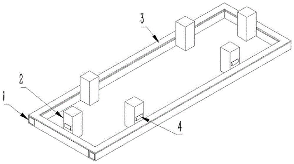
FIG. 1 is a diagram of a vehicle mount frame in accordance with a preferred embodiment of the present invention;
FIG. 2 is a schematic view of the vehicle bottom bracket frame and the battery box frame in a preferred embodiment of the invention;
FIG. 3 is an assembly view of the vehicle mount frame and the battery box frame in accordance with a preferred embodiment of the present invention;
the symbols 1 to 5 in the figure represent: vehicle-mounted bottom bracket frame 1, lateral support posts 2, cushion pads 3, elastic bodies 4 and battery box frame 5.
Detailed Description
The present invention will be described in detail with reference to specific examples. The following examples will assist those skilled in the art in further understanding the invention, but are not intended to limit the invention in any way. It should be noted that variations and modifications can be made by persons skilled in the art without departing from the spirit of the invention. All falling within the scope of the present invention.
As shown in fig. 1, 2 and 3, a schematic view of an embodiment of a damping structure of a heavy truck battery box of the present invention includes a vehicle-mounted bottom bracket frame 1 and a battery box frame 5, wherein the battery box frame 5 is mounted on a battery box, and the battery box is used as a driving energy source of the heavy truck; and the vehicle-mounted bottom support frame 1 can be arranged on a girder of the chassis of the heavy truck body and is used for being connected and fixed with the battery box frame 5, so that the battery box and the heavy truck are arranged. The vehicle-mounted bottom support frame and the battery box frame can be detachably connected.
As shown in fig. 1, the main body of the vehicle-mounted bottom bracket frame 1 is a rectangular frame body, the inner sides of which are welded with lateral pillars 2 respectively, and the lateral pillars 2 are arranged symmetrically. The height of each lateral strut 2 is slightly higher than that of the bottom support of the rectangular frame body, and an elastic body 4 with certain elasticity is arranged on the outer side surface of each lateral strut 2 higher than the bottom support, and the elastic body 4 has inward elastic compression deformation. A cushion pad 3 is further laid on the surface of the vehicle-mounted base frame 1, and the cushion pad 3 is fully laid around the perimeter direction of the rectangular frame body. In some embodiments, the cushion 3 may be made of a flexible material.
As shown in fig. 2, in an embodiment, the main body of the battery box frame 4 is a rectangular parallelepiped frame body, the shape and size of the rectangular parallelepiped frame body are matched with the shape and size of the battery box, and the internal space of the rectangular parallelepiped frame body is the installation space of the battery box. That is, the structure of the battery box frame 4 is adjustable according to the external contour shape and size of the battery box, i.e. is not limited to the rectangular parallelepiped frame body provided in the present embodiment.
As shown in fig. 1, 2 and 3, when the battery box frame 4 is installed above the vehicle-mounted base frame 1 by hoisting, the cushion pad 3 is located between the upper surface of the vehicle-mounted base frame 1 and the bottom surface of the bottom support of the battery box frame 4, namely, the horizontal contact surface positions of the vehicle-mounted base frame 1 and the battery box frame 4, and at this time, the cushion pad 3 can absorb a part of impact force in the vertical direction of the vehicle-mounted base frame 1 on the battery box frame 5 when the heavy truck travels, namely, the impact force in the Z direction shown in fig. 3, so that vibration reduction in the vertical direction is realized. Meanwhile, the elastic body 4 arranged on the lateral strut 2 is just between the outer side of the lateral strut 2 and the inner side of the bottom support of the battery box frame 4, namely the vertical contact surface positions of the lateral strut 2 and the battery box frame 4, and the existence of the elastic body 4 can absorb a part of impact force of the vehicle-mounted bottom bracket frame 1 on the battery box frame 5 in the horizontal direction, namely the X direction and the Y direction shown in fig. 3 when a heavy truck runs, so that the vibration reduction in the horizontal direction is realized.
In the embodiment of the invention, the cushion pad 3 and the elastic body 4 are arranged to absorb the impact force of the vehicle-mounted bottom bracket frame 1 on the battery box frame 5 when the heavy truck runs, so that the safety of the battery box is ensured.
In some preferred embodiments, the elastomer 4 may be an elastomer made of rubber, such as thermoplastic elastomer TPE/TPR, etc.; other materials with certain elasticity can also be used.
In some preferred embodiments, the cushion 3 can be made of flexible material, and the cushion 3 is arranged as a continuous whole in fig. 1, but in other embodiments, the same material, uniform and segmented arrangement can be adopted according to the size of the battery box, and the like, and the vibration damping effect can also be achieved. Of course, the height of the cushion pad 3 is slightly higher than the vehicle mount frame 1 surface.
The features of the preferred embodiments described above may be used alone in any embodiment, or may be used in combination in any embodiment without conflict.
In the drawings of the above embodiments, like reference numerals represent like parts or equivalent parts, and terms like "upper", "lower", "front", "rear", "left", "right", and the like used in the description are simply referred to with respect to the drawings for convenience of describing the present invention.
All the drawings of the above embodiments are only for convenience of explaining technical contents of the present invention; the numbers, positions of the components, interrelationships between the components, and dimensions of the components used to construct the preferred embodiment do not limit the technical solution itself, but extend to the entire area covered by the technical field.
The foregoing description of specific embodiments of the present invention has been presented. It is to be understood that the present invention is not limited to the specific embodiments described above, and that various changes and modifications may be made by one skilled in the art within the scope of the appended claims without departing from the spirit of the invention.