CN110901478B - Seat sliding device - Google Patents
Seat sliding device Download PDFInfo
- Publication number
- CN110901478B CN110901478B CN201910864102.0A CN201910864102A CN110901478B CN 110901478 B CN110901478 B CN 110901478B CN 201910864102 A CN201910864102 A CN 201910864102A CN 110901478 B CN110901478 B CN 110901478B
- Authority
- CN
- China
- Prior art keywords
- rail
- belt
- seat
- actuator
- lower rail
- Prior art date
- Legal status (The legal status is an assumption and is not a legal conclusion. Google has not performed a legal analysis and makes no representation as to the accuracy of the status listed.)
- Active
Links
Images


Classifications
-
- B—PERFORMING OPERATIONS; TRANSPORTING
- B60—VEHICLES IN GENERAL
- B60N—SEATS SPECIALLY ADAPTED FOR VEHICLES; VEHICLE PASSENGER ACCOMMODATION NOT OTHERWISE PROVIDED FOR
- B60N2/00—Seats specially adapted for vehicles; Arrangement or mounting of seats in vehicles
- B60N2/02—Seats specially adapted for vehicles; Arrangement or mounting of seats in vehicles the seat or part thereof being movable, e.g. adjustable
- B60N2/04—Seats specially adapted for vehicles; Arrangement or mounting of seats in vehicles the seat or part thereof being movable, e.g. adjustable the whole seat being movable
- B60N2/06—Seats specially adapted for vehicles; Arrangement or mounting of seats in vehicles the seat or part thereof being movable, e.g. adjustable the whole seat being movable slidable
- B60N2/07—Slide construction
- B60N2/0702—Slide construction characterised by its cross-section
- B60N2/0705—Slide construction characterised by its cross-section omega-shaped
-
- B—PERFORMING OPERATIONS; TRANSPORTING
- B60—VEHICLES IN GENERAL
- B60N—SEATS SPECIALLY ADAPTED FOR VEHICLES; VEHICLE PASSENGER ACCOMMODATION NOT OTHERWISE PROVIDED FOR
- B60N2/00—Seats specially adapted for vehicles; Arrangement or mounting of seats in vehicles
- B60N2/02—Seats specially adapted for vehicles; Arrangement or mounting of seats in vehicles the seat or part thereof being movable, e.g. adjustable
- B60N2/0224—Non-manual adjustments, e.g. with electrical operation
- B60N2/02246—Electric motors therefor
- B60N2/02253—Electric motors therefor characterised by the transmission between the electric motor and the seat or seat parts
-
- B—PERFORMING OPERATIONS; TRANSPORTING
- B60—VEHICLES IN GENERAL
- B60N—SEATS SPECIALLY ADAPTED FOR VEHICLES; VEHICLE PASSENGER ACCOMMODATION NOT OTHERWISE PROVIDED FOR
- B60N2/00—Seats specially adapted for vehicles; Arrangement or mounting of seats in vehicles
- B60N2/02—Seats specially adapted for vehicles; Arrangement or mounting of seats in vehicles the seat or part thereof being movable, e.g. adjustable
- B60N2/04—Seats specially adapted for vehicles; Arrangement or mounting of seats in vehicles the seat or part thereof being movable, e.g. adjustable the whole seat being movable
- B60N2/06—Seats specially adapted for vehicles; Arrangement or mounting of seats in vehicles the seat or part thereof being movable, e.g. adjustable the whole seat being movable slidable
- B60N2/07—Slide construction
- B60N2/0722—Constructive details
Landscapes
- Engineering & Computer Science (AREA)
- Aviation & Aerospace Engineering (AREA)
- Transportation (AREA)
- Mechanical Engineering (AREA)
- Seats For Vehicles (AREA)
Abstract
本发明提供一种能够以简单的结构使上导轨移动的座椅滑动装置。座椅滑动装置(2)具备:能够安装于车身的下导轨(10);可移动地与下导轨(10)卡合的上导轨(20);驱动辊(31);和致动器(32)。驱动辊(31)安装于上导轨(20),并被按压于下导轨(10)或车身。致动器(32)能够使驱动辊31旋转。由于该座椅滑动装置(2)只要在不具有动力的现有的座椅滑动装置中追加驱动辊和致动器即可,因此结构简单。
The present invention provides a seat sliding device capable of moving an upper rail with a simple structure. The seat sliding device (2) includes: a lower rail (10) capable of being mounted on a vehicle body; an upper rail (20) movably engaged with the lower rail (10); a driving roller (31); and an actuator (32 ). The driving roller (31) is installed on the upper guide rail (20) and pressed against the lower guide rail (10) or the vehicle body. The actuator ( 32 ) is capable of rotating the drive roller 31 . Since the seat slide device (2) only needs to add a drive roller and an actuator to the existing seat slide device without power, the structure is simple.
Description
技术领域technical field
本说明书所公开的技术涉及一种使汽车的座椅通过致动器移动的座椅滑动装置。The technology disclosed in this specification relates to a seat sliding device for moving a seat of an automobile by an actuator.
背景技术Background technique
已知有一种座椅滑动装置,其通过致动器使座椅移动(滑动)。座椅滑动装置具备安装在车体上的长条的下导轨和与下导轨卡合的上导轨。在上导轨上安装有座椅。日本专利特开2004-210113号公报所公开的座椅滑动装置在下导轨的内部配置有导螺杆。另一方面,上导轨具备:与导螺杆螺合的螺杆螺母以及使螺杆螺母旋转的致动器和蜗轮(wormgear)。当利用致动器和蜗轮使螺杆螺母旋转时,上导轨(即座椅)与螺杆螺母一起移动。There is known a seat sliding device which moves (slides) a seat by means of an actuator. The seat slide device includes a long lower rail attached to the vehicle body and an upper rail engaged with the lower rail. A seat is installed on the upper rail. In the seat slide device disclosed in Japanese Patent Application Laid-Open No. 2004-210113, a lead screw is disposed inside the lower rail. On the other hand, the upper rail includes a screw nut screwed with the lead screw, an actuator and a worm gear (wormgear) that rotate the screw nut. When the spindle nut is rotated using the actuator and worm gear, the upper rail (ie seat) moves with the spindle nut.
在日本专利特开2004-210113号公报所公开的座椅滑动装置中,具备覆盖下导轨的开口的百叶门,以使得尘埃不会附着在导螺杆上。百叶门为环形带状,卷绕在配置于下导轨的两端的辊之间。在一对辊之间平行地延伸的百叶门的上侧部分堵塞开口。在百叶门上设置有孔,上导轨通过该孔从下导轨的内侧向上方突出。是上导轨移动时百叶门追随移动的结构。In the seat sliding device disclosed in Japanese Patent Laid-Open No. 2004-210113, a louver covering the opening of the lower rail is provided so that dust does not adhere to the lead screw. The louver is in the shape of an endless belt and is wound between rollers arranged at both ends of the lower rail. An upper side portion of the louver extending in parallel between the pair of rollers blocks the opening. A hole is provided in the louver door, and the upper rail protrudes upward from the inner side of the lower rail through the hole. It is a structure in which the shutter door follows and moves when the upper guide rail moves.
日本专利特开2018-020665号公报所公开的座椅滑动装置具备与车身的底板接触的球状的旋转体和使旋转体向正交的两个方向旋转的多个致动器。由于旋转体向两个方向旋转,因此座椅滑动装置能够在车身的底板面上二维自由地移动。The seat sliding device disclosed in Japanese Patent Application Laid-Open No. 2018-020665 includes a spherical rotating body in contact with the floor of the vehicle body and a plurality of actuators that rotate the rotating body in two directions perpendicular to each other. Since the rotating body rotates in two directions, the seat slide device can freely move two-dimensionally on the floor surface of the vehicle body.
发明内容Contents of the invention
日本专利特开2018-020665号公报所公开的座椅滑动装置的移动机构的结构复杂,成本高。本说明书所公开的一个技术提供一种能够以简单的结构使上导轨通过致动器移动的座椅滑动装置。The moving mechanism of the seat sliding device disclosed in Japanese Patent Laid-Open No. 2018-020665 has a complicated structure and high cost. One technique disclosed in this specification provides a seat slide device capable of moving an upper rail by an actuator with a simple structure.
在日本专利特开2004-210113号公报所公开的座椅滑动装置中,为了防止尘埃附着在导螺杆上,需要复杂的机构。本说明书所公开的其他技术,提供一种能够以简单的结构防止可能成为使上导轨移动的机构的故障的尘埃的附着的座椅滑动装置。In the seat sliding device disclosed in Japanese Patent Application Laid-Open No. 2004-210113, a complicated mechanism is required to prevent dust from adhering to the lead screw. Another technique disclosed in this specification provides a seat slide device capable of preventing, with a simple structure, adhesion of dust that may cause a malfunction of a mechanism that moves an upper rail.
本说明书所公开的一个技术提供具有下述的结构的座椅滑动装置。该座椅滑动装置具备:能够安装于车身的下导轨;能够安装于座椅并且相对于下导轨可移动(可滑动)地卡合的上导轨;辊;和致动器。辊安装于上导轨。辊被按压于下导轨或车身。致动器使辊旋转。由于该座椅滑动装置只要在不具有动力的现有的座椅滑动装置中追加辊和致动器即可,因此结构简单。One technique disclosed in this specification provides a seat sliding device having the following structure. This seat slide device includes: a lower rail attachable to a vehicle body; an upper rail attachable to a seat and movably (slidably) engaged with the lower rail; rollers; and an actuator. The rollers are mounted on the upper rails. The rollers are pressed against the lower rail or body. An actuator rotates the roller. Since the seat slide device only needs to add rollers and actuators to the existing seat slide device without power, the structure is simple.
本说明书所公开的座椅滑动装置的一个方式可以具有以下的结构。下导轨配置在设置于车身的底面板的槽中。辊被按压于覆盖底面板的槽与下导轨之间的间隙的罩的上表面。罩可以是金属制,但若为树脂制则更好。树脂制的罩的摩擦系数较高,通过将由致动器驱动的辊按压于摩擦系数较高的树脂制的罩的上表面,辊不易滑动。树脂制的罩若在其下表面具备进入到槽与下导轨之间的垂下部则更好。One aspect of the seat slide device disclosed in this specification may have the following configurations. The lower rail is arranged in a groove provided in the bottom panel of the vehicle body. The roller is pressed against the upper surface of the cover covering the gap between the groove of the bottom panel and the lower rail. The cover may be made of metal, but it is more preferably made of resin. The resin cover has a high coefficient of friction, and by pressing the roller driven by the actuator against the upper surface of the resin cover with a high friction coefficient, the roller is less likely to slip. It is more preferable that the resin-made cover has the hanging part which enters between a groove and a lower rail on the lower surface.
本说明书所公开的座椅滑动装置的另一个方式也可以具有以下的结构。在上导轨上具备多个辊。一个或多个辊从下导轨的内侧被按压于下导轨的短边方向的一侧的侧板,剩余的辊从下导轨的内侧被按压于另一侧的侧板。致动器使多个辊的至少一个旋转。在这种方式的座椅滑动装置中,第一,由于被驱动的辊配置在下导轨的内侧,因此装置整体的大小与现有的座椅滑动装置相同即可。第二,由于辊被从下导轨的短边方向的中心侧朝向各个侧板按压,因此能够增大辊与侧板之间的摩擦力。因此,辊不易滑动。Another aspect of the seat slide device disclosed in this specification may have the following configurations. A plurality of rollers are provided on the upper rail. One or more rollers are pressed against the side plate on one side in the short-side direction of the lower rail from the inner side of the lower rail, and the remaining rollers are pressed against the other side plate from the inner side of the lower rail. The actuator rotates at least one of the plurality of rollers. In the seat slide device of this form, first, since the driven roller is disposed inside the lower rail, the overall size of the device may be the same as that of a conventional seat slide device. Second, since the rollers are pressed toward the respective side plates from the center side in the short-side direction of the lower rail, frictional force between the rollers and the side plates can be increased. Therefore, the roller is less likely to slip.
本说明书所公开的座椅滑动装置的再另一个方式也可以具有以下的结构。下导轨具备:底板;从底板的下导轨短边方向的两端向上方延伸的一对侧板;从各个侧板的上端朝向下导轨的短边方向的中心侧延伸的上板;和从各个上板的中心侧(下导轨短边方向的中心侧)的端部向下方延伸的内板。在上导轨上,具备与连结角部抵接的一对辊,连结角部为各个上板与同该上板连接的内板的连结角部。一对辊的各自的直径朝向中心侧(下导轨的短边方向的中心侧)逐渐增加。在上述方式的座椅滑动装置中,直径逐渐增加的一对辊由于下导轨的短边方向的刚性而被强力地夹在下导轨的一对连结角部之间。其结果是,辊与连结角部之间的摩擦力变大,辊不易滑动。Still another aspect of the seat sliding device disclosed in this specification may have the following configuration. The lower guide rail has: a base plate; a pair of side plates extending upward from both ends of the lower guide rail in the short side direction of the base plate; an upper plate extending from the upper end of each side plate toward the center side of the lower guide rail in the short side direction; An inner plate in which an end portion on the center side of the upper plate (the center side in the short-side direction of the lower rail) extends downward. The upper rail is provided with a pair of rollers that abut on connection corners that are connection corners between each upper plate and an inner plate connected to the upper plate. The respective diameters of the pair of rollers gradually increase toward the center side (the center side in the short-side direction of the lower rail). In the seat slide device of the above aspect, the pair of rollers whose diameter gradually increases is strongly sandwiched between the pair of connecting corners of the lower rail due to the rigidity in the short-side direction of the lower rail. As a result, the frictional force between the roller and the connection corner increases, making it difficult for the roller to slip.
本说明书所公开的其他技术提供具有下述结构的座椅滑动装置。座椅滑动装置具备:能够安装于车辆的下导轨;能够安装于座椅的上导轨;和带。带沿着下导轨配置。带的两端被固定。上导轨相对于下导轨可移动地卡合。上导轨具备输送带的致动器。并且,致动器向带的下表面传递动力。在该座椅滑动装置中,由于向尘埃不易附着的带的下表面传递动力而使上导轨(座椅)移动,因此不易产生由尘埃的附着引起的故障。Another technique disclosed in this specification provides a seat sliding device having the following structure. The seat slide device includes: a lower rail attachable to a vehicle; an upper rail attachable to a seat; and a belt. The belt is configured along the lower rail. Both ends of the strap are secured. The upper rail is movably engaged with the lower rail. The upper rails are equipped with actuators for the conveyor belt. Also, the actuator transmits power to the lower surface of the belt. In this seat slide device, the upper rail (seat) is moved by transmitting power to the lower surface of the belt where dust is less likely to adhere, so troubles caused by adhesion of dust are less likely to occur.
致动器也可以具备与带的下表面接触的驱动辊或驱动齿轮。在前者的情况下,带优选为通过下表面与驱动辊之间的摩擦传递动力的摩擦带。后者的情况下,优选为在下表面设置有与驱动齿轮卡合的齿的带齿的带。带齿的带也被称为齿形带(Cogged Belt)。The actuator may also have a drive roller or a drive gear in contact with the lower surface of the belt. In the former case, the belt is preferably a friction belt that transmits power by friction between the lower surface and the drive roller. In the latter case, a toothed belt is preferably provided on the lower surface with teeth that engage with the drive gear. A toothed belt is also called a cogged belt.
带也可以配置在下导轨的内部。与带露出到车身的底板相比,不易附着尘埃。另外,由于搭乘者看不到带,因此美观性好。The belt can also be arranged inside the lower rail. Dust is less likely to adhere to the underbody with the belt exposed to the vehicle body. In addition, since the belt cannot be seen by the rider, the appearance is good.
或者,也可以是,下导轨的上部沿导轨长边方向开口,带覆盖其开口。用于使上导轨(座椅)移动的带兼作防止尘埃进入下导轨内部的罩。另外,带齿的带的情况下,带的齿也可以与下导轨的开口嵌合。带齿的带不易脱离开口。Or, it is also possible that the upper part of the lower guide rail is opened along the long side direction of the guide rail, and the belt covers the opening. The belt used to move the upper rail (seat) doubles as a cover to keep dust from getting inside the lower rail. In addition, in the case of a toothed belt, the teeth of the belt may be fitted into the openings of the lower rail. The toothed belt does not easily come out of the opening.
上导轨的致动器的一个例子如下。致动器具备:配置在上导轨的导轨长边方向的两端,并且与堵塞开口的带的上表面接触的一对引导件;和配置在一对引导件之间,并且与离开开口的带的下表面抵接的驱动辊或与下表面的齿卡合的驱动齿轮。能够以简单的机构使上导轨移动。An example of an actuator for the upper rail is as follows. The actuator includes: a pair of guides arranged at both ends of the upper rail in the guide rail longitudinal direction and in contact with the upper surface of the belt blocking the opening; The lower surface of the drive roller abuts or the drive gear engages with the teeth of the lower surface. The upper rail can be moved with a simple mechanism.
对于本说明书所公开的技术的详细情况和进一步的改良,在以下的“具体实施方式”中进行说明。The details and further improvements of the techniques disclosed in this specification will be described in the following "Detailed Description of Embodiments".
附图说明Description of drawings
图1是第一实施例的座椅滑动装置的侧视图。Fig. 1 is a side view of a seat sliding device of a first embodiment.
图2是用与导轨长边方向正交的平面切断的座椅滑动装置的截面图。Fig. 2 is a sectional view of the seat slide device cut along a plane perpendicular to the longitudinal direction of the guide rail.
图3是第二实施例的座椅滑动装置的截面图。Fig. 3 is a sectional view of a seat sliding device of a second embodiment.
图4是第三实施例的座椅滑动装置的截面图。Fig. 4 is a sectional view of a seat sliding device of a third embodiment.
图5是第四实施例的座椅滑动装置的截面图。Fig. 5 is a sectional view of a seat sliding device of a fourth embodiment.
图6是第五实施例的座椅滑动装置的截面图。Fig. 6 is a sectional view of a seat sliding device of a fifth embodiment.
图7是第六实施例的座椅滑动装置的截面图。Fig. 7 is a sectional view of a seat sliding device of a sixth embodiment.
图8是第七实施例的座椅滑动装置的截面图。Fig. 8 is a sectional view of a seat sliding device of a seventh embodiment.
图9是第八实施例的座椅滑动装置的截面图。Fig. 9 is a sectional view of a seat sliding device of an eighth embodiment.
图10是第八实施例的座椅滑动装置的示意性俯视图。Fig. 10 is a schematic plan view of the seat slide device of the eighth embodiment.
图11是第九实施例的座椅滑动装置的侧视图。Fig. 11 is a side view of the seat sliding device of the ninth embodiment.
图12是用与导轨长边方向正交的平面切断的座椅滑动装置的截面图。Fig. 12 is a cross-sectional view of the seat slide device cut along a plane perpendicular to the longitudinal direction of the guide rail.
图13是图12的XIII-XIII线截面图。Fig. 13 is a cross-sectional view taken along line XIII-XIII in Fig. 12 .
图14是第十实施例的座椅滑动装置的截面图。Fig. 14 is a sectional view of a seat sliding device of a tenth embodiment.
图15是沿图14的XV-XV线的截面图。Fig. 15 is a cross-sectional view taken along line XV-XV in Fig. 14 .
图16是第十一实施例的座椅滑动装置的立体图。Fig. 16 is a perspective view of a seat sliding device of an eleventh embodiment.
图17是沿图16的XVII-XVII线的截面图。Fig. 17 is a sectional view taken along line XVII-XVII of Fig. 16 .
图18是沿图16的XVIII-XVIII线的截面图。Fig. 18 is a sectional view taken along line XVIII-XVIII of Fig. 16 .
图19是将第十一实施例的座椅滑动装置用XZ平面切断的截面图。Fig. 19 is a cross-sectional view taken along the XZ plane of the seat slide device of the eleventh embodiment.
图20是将第十二实施例的座椅滑动装置用XZ平面切断的截面图。Fig. 20 is a cross-sectional view taken along the XZ plane of the seat slide device of the twelfth embodiment.
图21是在上导轨的前方切断第十三实施例的座椅滑动装置的截面图。Fig. 21 is a cross-sectional view of the seat slide device of the thirteenth embodiment cut in front of the upper rail.
具体实施方式detailed description
(第一实施例)参照附图对第一实施例的座椅滑动装置2进行说明。图1表示安装在汽车上的座椅滑动装置2的侧视图。座椅滑动装置2由下导轨10和上导轨20构成。下导轨10为长条。上导轨20相对于下导轨10在其长边方向上可移动(可滑动)地安装。下导轨10固定于车身的底板90。上导轨20安装在座椅80的座垫81的下部。上导轨20通过未图示的框架安装在座垫81的下部。座椅滑动装置2分别安装在座垫81的下部的左右。图中的坐标系的X方向相当于下导轨10和上导轨20的导轨长边方向。Y方向相当于导轨短边方向。图中的坐标系的+Z方向表示上方。(First Embodiment) A
在上导轨20安装有由致动器驱动的驱动辊31。在图1中省略了致动器的图示。驱动辊31与底板90接触。上导轨20能够通过由致动器驱动的驱动辊31相对于下导轨10移动。即,座椅滑动装置2能够以电动方式使座椅移动(滑动)。A
图2表示座椅滑动装置2的截面图。图2的截面表示将下导轨10和上导轨20用与导轨长边方向(X方向)正交的平面切断的截面。图2是在比后述的致动器30靠前方切断上导轨20的截面图。另外,在上导轨20上,设置有将上导轨20相对于下导轨10固定的锁定机构,但省略了锁定机构的图示。锁定机构与现有的座椅滑动装置所具备的机构相同,因此省略说明。FIG. 2 shows a cross-sectional view of the
参照图2,首先对下导轨10的形状进行说明。下导轨10收纳在设置于底面板(floorpanel)90的导轨槽91中。下导轨10具备安装于车身的底板3、一对外纵板4、一对上板5、一对内纵板6。一对外纵板4在导轨短边方向(图中的Y方向)上从底板3的两端分别向上方延伸。一对上板5从各个外纵板4的上端向导轨短边方向的中央横向地延伸。一对内纵板6从各个上板5的内侧端向下方延伸。一对内纵板6相互对向。在一对内纵板6之间,下导轨10向上方开口。下导轨10的上表面沿导轨长边方向细长地开口。Referring to FIG. 2 , first, the shape of the
对上导轨20进行说明。上导轨20的主体下部22位于下导轨10的内侧,支撑从动辊23。从动辊23与下导轨10的底板3接触,使上导轨20的移动顺畅。上导轨20能够沿下导轨10的长边方向移动(能够滑动)。上导轨20的主体上部21比下导轨10更向上侧露出。在主体上部21安装有未图示的框架,在该框架上固定有座垫81(参照图1)。主体上部21和主体下部22通过下导轨10的开口连接。换言之,上导轨20的一部分(主体下部22)位于下导轨10的内部,剩余部分(主体上部21)通过下导轨10的开口而比下导轨10向上方突出。The
在上导轨20的主体上部21固定有致动器30,在致动器30的输出轴上固定有驱动辊31。致动器30由电机和齿轮组构成。电机的驱动轴与齿轮组的输入轴连结,齿轮组的输出轴(致动器30的输出轴)与驱动辊31连结。齿轮组将电机的旋转减速并传递给驱动辊31。驱动辊31被按压于底面板90的上表面90a。驱动辊31通过致动器30而旋转。如上所述,上导轨20能够通过致动器30和驱动辊31相对于下导轨10在其长边方向上移动。在驱动辊31的与底板90接触的外周面上粘贴有橡胶,驱动辊31能够相对于底板90不打滑地旋转。An
如上所述,第一实施例的座椅滑动装置2具有仅在不具备致动器的现有的座椅滑动装置中追加了致动器30和驱动辊31的简单的结构。As described above, the
(第二实施例)图3表示第二实施例的座椅滑动装置2a的截面图。图3的截面图与图2的截面图同样地,表示将下导轨10和上导轨20用与导轨长边方向(图中的坐标系的X方向)正交的平面切断的截面。与图2同样地,图3是在致动器30的前方切断上导轨20的截面图。(Second Embodiment) Fig. 3 shows a cross-sectional view of a
第二实施例的座椅滑动装置2a的上导轨20也与第一实施例的座椅滑动装置2同样地具备致动器30和驱动辊31。驱动辊31与致动器30的输出轴连结。与第一实施例的座椅滑动装置2不同,驱动辊31不是被按压于底板90的上表面90a,而是被按压于下导轨10的上板5。第二实施例的座椅滑动装置2a的上导轨20也能够通过致动器30和驱动辊31相对于下导轨10在其长边方向上以电动方式进行移动。The
(第三实施例)图4表示第三实施例的座椅滑动装置2b的截面图。图4的截面图也与图2、图3的截面图同样地,表示将下导轨10和上导轨20用与导轨长边方向(图中的坐标系的X方向)正交的平面切断的截面。(Third Embodiment) Fig. 4 shows a cross-sectional view of a
在第三实施例的座椅滑动装置2b的上导轨20上,也安装有致动器30和驱动辊31。但是,在第三实施例的情况下,致动器30经由固定于上导轨20的主体上部21的框架29安装在上导轨20上。如上所述,在框架29上安装有座垫(参照图1)。在致动器30的输出轴上连结有驱动辊31,驱动辊31被按压于底面板90的上表面。第三实施例的座椅滑动装置2b也能够通过致动器30和驱动辊31使上导轨20相对于下导轨10在其长边方向上以电动方式进行移动。On the
(第四实施例)图5表示第四实施例的座椅滑动装置2c的截面图。第五实施例的座椅滑动装置2c具备一对T形状嵌条93。(Fourth Embodiment) Fig. 5 shows a cross-sectional view of a
一对T形状嵌条93是为了堵塞设置于底板90的导轨槽91的内侧面94与下导轨10之间的间隙而设置的。T形状嵌条93具备:覆盖底面板90的上表面和下导轨10的上板5的平坦部93b;以及在导轨短边方向上从平坦部93b的下表面中央向下方延伸的垂下部93a。垂下部93a插入导轨槽91的内侧面94与下导轨10的间隙中。换言之,T形状嵌条93进入导轨槽91与下导轨10之间的间隙,并且覆盖间隙的两侧(底面板90和下导轨10的上板5)。T形状嵌条93由柔软性高的树脂制成。A pair of T-shaped
在第四实施例的座椅滑动装置2c中,驱动辊31被按压于T形状嵌条93的上表面。如上所述,T形状嵌条93由柔软性高的树脂制成,表面的摩擦系数较高。因此,驱动辊31难以相对于T形状嵌条93滑动。第四实施例的座椅滑动装置2c具备驱动辊31不易滑动的优点。另外,由于T形状嵌条93具备插入导轨槽91与下导轨10之间的间隙的垂下部93a,因此具备即使驱动辊31在上表面移动,T形状嵌条93也不易偏移的优点。In the
T形状嵌条93是覆盖导轨槽91与下导轨10之间的间隙的罩的一个例子。虽然比不上采用T形状嵌条93时得到的优点,但也可以代替T形状嵌条93而使驱动辊31在覆盖导轨槽91与下导轨10之间的间隙的罩上移动。罩优选为树脂制,但也可以由金属以外的材料制成。The T-shaped
(第五实施例)图6表示第五实施例的座椅滑动装置2d的截面图。在座椅滑动装置2d中,下导轨10固定于平坦的底面板90的上表面,外纵板4露出。驱动辊31从外侧被按压于下导轨10露出的外纵板4。(Fifth Embodiment) Fig. 6 shows a cross-sectional view of a
(第六实施例)图7表示第六实施例的座椅滑动装置2e的截面图。在座椅滑动装置2e中,驱动辊31被按压于下导轨10的内纵板6。另外,在图7中,省略了对驱动辊31进行驱动的致动器的图示。在第六实施例的座椅滑动装置2e中,由于驱动辊31位于下导轨10的内侧,因此抑制了装置整体的体积的增加。(Sixth Embodiment) Fig. 7 shows a cross-sectional view of a
(第七实施例)图8表示第七实施例的座椅滑动装置2f的截面图。对下导轨10的结构性特征进行再记载。下导轨10具备底板3、一对外纵板4、一对上板5、一对内纵板6。一对外纵板4从底板3的导轨短边方向的两端向上方延伸。一对上板5分别从各个外纵板4的上端向下导轨10的导轨短边方向的中心侧延伸。一对内纵板6分别从各个上板5的导轨短边方向的中心侧的端部向下方延伸。(Seventh Embodiment) Fig. 8 shows a cross-sectional view of a
在座椅滑动装置2f的上导轨20上,具备一对驱动辊131。一对驱动辊131也与致动器30的输出轴连结。一对驱动辊131分别与下导轨10的各个上板5与内纵板6的连结角部8抵接。驱动辊131的直径从下导轨10的短边方向的外侧向中心侧逐渐增加。换言之,驱动辊131具有从导轨短边方向的外侧向中心侧扩径的锥形状。A pair of
另外,在致动器30的上部与上导轨20的主体上部21之间具备弹簧33。弹簧33将致动器30向下方按压。弹簧33通过致动器30将驱动辊131按压于下导轨10。In addition, a
在第七实施例的座椅滑动装置2f中,朝向下导轨10的导轨短边方向的中心侧直径逐渐增加的驱动辊131被按压于下导轨10的连结角部8。通过该按压力,在一对连结角部8产生朝向导轨外侧的负荷,一对连结角部8朝向导轨短边方向的外侧变形。对变形的恢复力使一对连结角部8朝向导轨短边方向的中心侧地起作用。该复原力强力地作用于锥形状的驱动辊131的锥面。通过作用于驱动辊131的复原力,驱动辊131更加不易滑动。第七实施例的座椅滑动装置2f的驱动辊131相对于下导轨10明显变得不易滑动。In the
(第八实施例)图9表示第八实施例的座椅滑动装置2g的截面图。在座椅滑动装置2g中,驱动辊31从下导轨10的内侧被按压于外纵板4。另外,在图9中,省略了对驱动辊31进行驱动的致动器的图示。在第八实施例的座椅滑动装置2g中,由于驱动辊31位于下导轨10的内侧,因此抑制了装置整体的体积的增加。(Eighth Embodiment) Fig. 9 shows a cross-sectional view of a
图10表示座椅滑动装置2g的示意性俯视图。图10是从图中的坐标系的+Z方向观察座椅滑动装置2g的图。在图10中,用假想线绘制上导轨20。由于致动器30、驱动辊31和第二从动辊39隐藏于上导轨20,因此用虚线绘制。FIG. 10 shows a schematic top view of the
如图10所示,座椅滑动装置2g除了驱动辊31之外还具备两个第二从动辊39。驱动辊31从下导轨10的导轨短边方向的中心侧被按压于下导轨10的一侧的外纵板4,两个第二从动辊39从下导轨10的导轨短边方向的中心侧被按压于另一侧的外纵板4。座椅滑动装置2g具备多个辊(驱动辊31和第二从动辊39),其中的一个(驱动辊31)从下导轨10的中心侧被按压于一侧的外纵板4,剩余的辊(第二从动辊39)从下导轨10的中心侧被按压于另一侧的外纵板4。即,在座椅滑动装置2g中,多个辊从下导轨的导轨短边方向的中心侧向两方的外侧分散地被按压。通过该结构,驱动辊31被强力地按压于下导轨10的外纵板4,因此驱动辊31相对于下导轨10更加不易滑动。As shown in FIG. 10 , the
另外,座椅滑动装置2g也可以具备两个以上的驱动辊。即,座椅滑动装置具有多个辊,这些辊的一个或几个从下导轨的内侧被按压于一侧的侧板,剩余的辊从下导轨的内侧被按压于另一侧的侧板。由致动器驱动多个辊中的一个或几个辊。In addition, 2 g of seat slide apparatuses may be equipped with two or more drive rollers. That is, the seat slide device has a plurality of rollers, one or several of these rollers are pressed against one side plate from the inner side of the lower rail, and the remaining rollers are pressed against the other side plate from the inner side of the lower rail. One or several of the rollers are driven by actuators.
对在实施例中说明的技术相关的注意点进行说明。致动器30所具备的电机是电动机。即,实施例的座椅滑动装置2、2a~2g能够以电动方式使上导轨(即座椅)移动。另外,启动致动器的开关设置在座椅上。启动致动器的开关也可以设置在驾驶席上。Notes on techniques described in the examples will be described. The motor included in the
实施例的座椅滑动装置2、2a~2g均能够以简单的结构使上导轨20(即座椅)以电动方式进行移动。The
(第九实施例)参照附图对第九实施例的座椅滑动装置2h进行说明。图11表示安装在汽车上的座椅滑动装置2h的侧视图。座椅滑动装置2由下导轨10和上导轨20构成。上导轨20相对于下导轨10可滑动(可滑动)地安装。下导轨10固定于车辆的底面板90。上导轨20安装在座椅80的座垫81的下部。座椅滑动装置2分别安装在座垫81的下部的左右。详细情况将在后面叙述,但在上导轨20上具备致动器。在图11中省略了致动器的图示。上导轨20能够通过致动器相对于下导轨10移动。即,座椅滑动装置2能够以电动方式使座椅移动(滑动)。(Ninth Embodiment) A
图12表示座椅滑动装置2h的截面图。图2的截面表示将下导轨10和上导轨20用与导轨长边方向(X方向)正交的平面切断的截面。图12是在比后述的致动器30更靠前方切断上导轨20的截面图。图13表示沿图12的XIII-XIII线的截面图。图13相当于用横穿致动器30的平面切断的截面。图12相当于沿图13的XII-XII线的截面图。图12、图13的座椅滑动装置2h分别安装在座垫81的下部的左右。在图12中,为了帮助理解,带40(后述)的截面以外的部分用灰色表示。Fig. 12 shows a cross-sectional view of the
在上导轨20上,设置有将上导轨20相对于下导轨10固定的锁定机构,但省略了锁定机构的图示。锁定机构与现有的座椅滑动装置所具备的机构相同,因此省略说明。A locking mechanism for fixing the
座椅滑动装置2h的下导轨10和上导轨20的基本结构与座椅滑动装置2相同,因此省略详细的说明。The basic structure of the
在下导轨10的短边方向的旁边配置有带40。如图13所示,带40沿下导轨10的长边方向延伸,两端通过螺栓99固定于辅助板7。辅助板7与下导轨10的底板3连结,沿一个外纵板4向上方折弯,以与上板5大致相同的高度向下导轨10的短边方向(Y方向)的外侧折弯。带40载置在辅助板7上。在带40与辅助板7之间,夹持有T形状嵌条92b。
带40是带齿的带,带40以齿41位于下表面侧的方式配置。齿41与后述的驱动齿轮32卡合。带40由树脂或橡胶制成。The
一对T形状嵌条92a、92b是为了堵塞下导轨10的开口而设置的。T形状嵌条92a夹在导轨槽91与外纵板4的间隙中而被固定。T形状嵌条92b夹在外纵板4与辅助板7之间而固定。一个T形状嵌条92b在导轨短边方向上朝下导轨10的外侧大幅扩展。T形状嵌条92b扩展到带40的下侧。T形状嵌条92a、92b由柔软的树脂制成。A pair of T-shaped
在上导轨20上,设置有致动器30。致动器30将沿下导轨10配置的带40卷入,在带40的下表面具备传递动力的驱动齿轮32。致动器30具备两个引导辊31a、31b。两个引导辊31a、31b与载置在辅助板7上的带40的上表面接触。在两个引导辊31a、31b之间配置有驱动齿轮32。通过了一个引导辊31a的带40被拉离辅助板7,卷绕在驱动齿轮32的上侧。驱动齿轮32与带40的下表面的齿41卡合。通过了驱动齿轮32的上侧的带40通过另一个引导辊31b的下方,再次载置在辅助板7上。On the
驱动齿轮32通过电机35而旋转。当驱动齿轮32旋转时,向带40传递动力。动力被传递到带40的下表面的齿41。如上所述,带40的两端固定于辅助板7。因此,通过被带40传递的动力,上导轨20沿导轨长边方向移动。即,座椅滑动装置2能够以电动方式使座椅移动。驱动齿轮32和引导辊31a、31b被罩61覆盖。The
在座椅滑动装置2h中,驱动齿轮32向带40的下表面传递动力。带40的齿41设置于带40的下表面。因此,尘埃不易附着在齿41上。由于尘埃不易附着在传递动力的齿41上,因此不易在以电动方式移动座椅的机构中产生不良情况。另外,由于在带40的下表面侧设置有齿41,因此车辆的搭乘者看不到齿41,美观性好。In the
另外,由于带40被载置在安装于下导轨10的底板3的辅助板7上,因此能够与下导轨10一起安装在底面板90上。将包括带40的座椅滑动装置2安装在车辆上的操作变得容易。In addition, since the
(第十实施例)参照图14、图15对第十实施例的座椅滑动装置2i进行说明。图14表示将座椅滑动装置2i用导轨短边方向(图中的Y方向)的中央切断的截面。图15表示沿图14的XV-XV线的截面。图14相当于沿图15的XIV-XIV线的截面。座椅滑动装置2i具备上导轨120和下导轨110。在图14、图15中,也省略了将上导轨120相对于下导轨110固定的锁定机构的图示。(Tenth Embodiment) A
在座椅滑动装置2i中,带40配置在下导轨110的内侧。带40以齿41位于下侧的方式配置。带40载置在底板3上。带40的两端通过螺栓99固定于下导轨110。In the
上导轨120的致动器130的除了电机35以外的部件装备在上导轨120的主体内部。致动器130除了电机35之外,还具备一对引导辊31a、31b、驱动齿轮32a、从动齿轮32b、副辊33a、33b。引导辊31a、31b与载置在底板3上的带40的上表面接触。通过了引导辊31a的带40被拉离底板3,并卷绕在驱动齿轮32a的上侧。设置于带40的下表面的齿41与驱动齿轮32a卡合。带40夹在驱动齿轮32a与副辊33a之间,不会脱离驱动齿轮32a。驱动齿轮32a通过电机35而旋转。当驱动齿轮32a旋转时,向带40的下表面传递动力。由于带40的两端固定于下导轨110,因此上导轨120通过电机35的驱动力而移动。即,座椅以电动方式移动。Components of the
通过了驱动齿轮32a与副辊33a之间的带40通过从动齿轮32b与副辊33b之间,进而通过引导辊31b的下侧,返回到底板3上。The
在第十实施例的座椅滑动装置2i中,致动器130(驱动齿轮32a)也向带40的下表面传递动力。由于在带40的下表面上设置有齿41,因此尘埃不易附着在齿41上。因此,在使上导轨120(座椅)移动的机构中不易产生不良情况。另外,在座椅滑动装置2i中,带40配置在下导轨110内,并且通过上导轨120的内部。因此,由于带40从周围看不到,因此座椅滑动装置2i的美观性好。In the
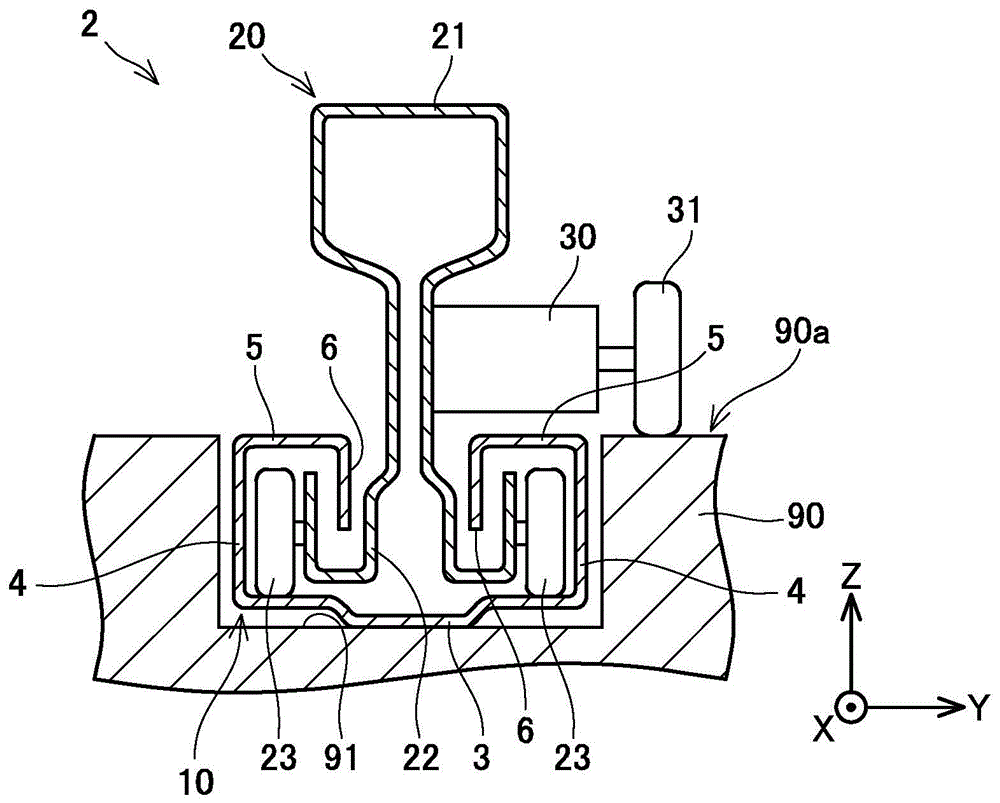
(第十一实施例)参照图16~图19对第十一实施例的座椅滑动装置2j进行说明。图16表示座椅滑动装置2j的立体图。图17是沿图16的XVII-XVII线的截面图,图18是沿图16的XVIII-XVIII线的截面图。图19是将座椅滑动装置2j在短边方向的中央切断的截面图。图19是用图中的坐标系的XZ平面将座椅滑动装置2j切断的截面图。(Eleventh Embodiment) A
在座椅滑动装置2j中,带40以堵塞下导轨210的开口W的方式配置。开口W是一对内纵板6之间的空间。换言之,下导轨210在其上表面具备沿导轨长边方向细长的开口W。如图17所示,上导轨220的主体下部22与主体上部21通过开口W连接。位于下导轨210的内侧的主体下部22是支撑从动辊23的部分。如图16所示,带40的两端通过螺栓99固定在下导轨110的前端11a和后端11b。在图18中,为了帮助理解,带40的截面以外的部分用灰色表示。带40是在下表面设置有齿41的带齿的带。齿41的宽度比带40的宽度窄,齿41与下导轨210的开口W嵌合。In the
设置在上导轨220上的致动器230除了电机35之外装备在上导轨220的主体上部21中。致动器230具备一对引导辊31a、31b、驱动齿轮32a、从动齿轮32b、副辊33a、33b,在图16中,省略了电机35和副辊33a、33b的图示。The
引导辊31a、31b分别配置在上导轨220的主体上部21的导轨长边方向的两端。引导辊31a、31b的下端与带40的上表面接触。在图19中,在上导轨220向图的左侧移动时,通过了行进方向的引导辊31a的带从下导轨210的开口W被拉起,在主体上部21的内部挂在驱动齿轮32a的上表面。带40的齿41与驱动齿轮32a卡合。当驱动齿轮32a通过电机35而旋转时,其动力被传递到带40的下表面。由于带40的两端固定于下导轨210,因此上导轨220通过电机35的动力而移动。即,上导轨220(座椅)以电动方式移动。The
通过了驱动齿轮32a与副辊33a之间的带40通过从动齿轮32b与副辊33b之间。带40通过上导轨220的行进方向的后侧的引导辊31b的下方,再次返回到开口W。The
在座椅滑动装置2j中,由于带40堵塞下导轨210的开口W,因此尘埃不易进入下导轨210的内部。另外,由于看不到下导轨210的开口W,因此美观性好。进而,由于传递动力的齿41设置在带40的下表面,因此尘埃不易附着在齿41上。在上导轨220移动时,堵塞开口W的带40从开口W被拉起,通过上导轨220的主体上部21的内部,在行进方向的后侧再次返回到开口W。带40不妨碍上导轨220的移动地堵塞下导轨210的开口W。In the
(第十二实施例)参照图20对第十二实施例的座椅滑动装置2k进行说明。图20是将座椅滑动装置2k用图中的坐标系的XZ平面切断的截面图。在图20中,也省略了将上导轨220相对于下导轨210固定的锁定机构的图示。(Twelfth Embodiment) A
在座椅滑动装置2k中,与带40卡合的从动齿轮36被凸轮37支撑。凸轮37的一端可旋转地支撑于上导轨220的主体上部21,在另一端安装有从动齿轮36。从动齿轮36由凸轮37可上下摆动地支撑。在凸轮37上,安装有弹簧38。弹簧38的一端固定于凸轮37,另一端在凸轮37的上方固定于主体上部21。凸轮37(即从动齿轮36)通过弹簧38而被向上方施力。由于在从动齿轮36的上侧卷绕有带40,因此通过弹簧38的作用力,在其长边方向上向带40施加张力。通过向带40施加长边方向的张力,防止了堵塞开口W的带40的松动。第十二实施例的座椅滑动装置2k除了具备从动齿轮36、凸轮37、弹簧38以外,与第十一实施例的座椅滑动装置2j的结构相同。从动齿轮36、凸轮37、弹簧38是向带40施加长边方向的张力的机构。In the
(第十三实施例)参照图21对第五实施例的座椅滑动装置2l进行说明。图21是将座椅滑动装置2l在上导轨320的前方切断的截面图。即,在图21中绘制有下导轨310的截面和上导轨320的正面。在座椅滑动装置2l中,采用平坦的摩擦带140而不是带齿的带。摩擦带140的下表面是动力传递面。在图21中,为了帮助理解,摩擦带140的截面以外的部分用灰色表示。(Thirteenth Embodiment) A
另一方面,在下导轨310上,在上板5与内纵板6的连接部位设置有沿导轨长边方向的凹部9。摩擦带140与位于开口W的宽度方向的左右的一对凹部9嵌合。通过摩擦带140与下导轨310的凹部嵌合,不易脱离开口W。On the other hand, on the
座椅滑动装置2l具备致动器330。致动器330具备驱动辊52来代替第十一实施例的座椅滑动装置2k的驱动齿轮32a。致动器330与致动器230同样地具备一对引导辊31a、31b、电机35、副辊53。一对引导辊31a、31b分别配置在上导轨320的主体上部21的导轨长边方向的两端。引导辊31a配置在主体上部21的前端,引导辊31b在图21中看不到,但配置在主体上部21的后端。引导辊31a、31b的下端与摩擦带140的上表面接触。前方的引导辊31a与嵌合于下导轨310的摩擦带140的上表面接触。在上导轨320向前方(图中的坐标系的+X方向)移动时,通过了行进方向的引导辊31a的摩擦带140从下导轨310的开口W被拉起,在主体上部21的内部挂在驱动辊52的上表面。通过了驱动辊52的摩擦带140通过后端的引导辊31b的下侧,再次与开口W嵌合。The
摩擦带140夹在驱动辊52与副辊53之间。驱动辊52通过电机35而旋转。当驱动辊52通过电机35而旋转时,其动力摩擦力被传递到带140的下表面。由于摩擦带140的两端固定于下导轨310,因此上导轨320通过电机35的动力而移动。即,上导轨320(座椅)以电动方式移动。座椅滑动装置2l中,由于摩擦带140的动力传递面为下表面,因此尘埃不易附着在动力传递面上。因此,驱动辊52与摩擦带140之间的摩擦力不易降低。The
对在实施例中说明的技术相关的注意点进行说明。第九实施例至第十三实施例的座椅滑动装置2h~2l都能够以简单的结构防止可能成为使上导轨移动的机构的故障的尘埃的附着。Notes on techniques described in the examples will be described. The
带40、摩擦带140由柔软的树脂或橡胶制成。带40也可以是由多个小片制成,相邻的小片可摆动地连结的结构。The
实施例的引导辊31a、31b相当于一对引导件的一个例子。引导件也可以是相对于带滑动的销,以代替随着带的移动而旋转的辊。The
以上对本发明的具体例进行了详细说明,但这些只不过是例示,并不限定权利要求的范围。在权利要求书所记载的技术中,包括将以上例示的具体例子进行各种变形、变更。在本说明书或附图中说明的技术要素通过单独或各种组合来发挥技术上的有用性,并不限定于申请时权利要求所记载的组合。另外,本说明书或附图所例示的技术能够同时达到多个目的,且在实现其中的一个目的的本身中具有技术上的有用性。Specific examples of the present invention have been described in detail above, but these are merely illustrations and do not limit the scope of the claims. Various modifications and changes of the specific examples illustrated above are included in the technology described in the claims. The technical elements described in this specification or the drawings exhibit technical usefulness individually or in various combinations, and are not limited to the combinations described in the claims at the time of application. In addition, the technology illustrated in this specification or the drawings can simultaneously achieve a plurality of purposes, and is technically useful in achieving one of the purposes itself.
Claims (1)
Priority Applications (1)
| Application Number | Priority Date | Filing Date | Title |
|---|---|---|---|
| CN202210956471.4A CN115158117B (en) | 2018-09-14 | 2019-09-12 | Seat sliding device |
Applications Claiming Priority (4)
| Application Number | Priority Date | Filing Date | Title |
|---|---|---|---|
| JP2018-172147 | 2018-09-14 | ||
| JP2018172147A JP7058578B2 (en) | 2018-09-14 | 2018-09-14 | Seat slide device |
| JP2019-038848 | 2019-03-04 | ||
| JP2019038848A JP7219639B2 (en) | 2019-03-04 | 2019-03-04 | seat slide device |
Related Child Applications (1)
| Application Number | Title | Priority Date | Filing Date |
|---|---|---|---|
| CN202210956471.4A Division CN115158117B (en) | 2018-09-14 | 2019-09-12 | Seat sliding device |
Publications (2)
| Publication Number | Publication Date |
|---|---|
| CN110901478A CN110901478A (en) | 2020-03-24 |
| CN110901478B true CN110901478B (en) | 2023-01-03 |
Family
ID=69814694
Family Applications (2)
| Application Number | Title | Priority Date | Filing Date |
|---|---|---|---|
| CN201910864102.0A Active CN110901478B (en) | 2018-09-14 | 2019-09-12 | Seat sliding device |
| CN202210956471.4A Active CN115158117B (en) | 2018-09-14 | 2019-09-12 | Seat sliding device |
Family Applications After (1)
| Application Number | Title | Priority Date | Filing Date |
|---|---|---|---|
| CN202210956471.4A Active CN115158117B (en) | 2018-09-14 | 2019-09-12 | Seat sliding device |
Country Status (1)
| Country | Link |
|---|---|
| CN (2) | CN110901478B (en) |
Families Citing this family (3)
| Publication number | Priority date | Publication date | Assignee | Title |
|---|---|---|---|---|
| CN113665442A (en) | 2020-05-14 | 2021-11-19 | 李尔公司 | Track assembly |
| EP4052959B1 (en) | 2021-03-04 | 2024-09-25 | IMS Gear SE & Co. KGaA | Seat length adjustment unit, seat assembly and motor vehicle |
| EP4082827B1 (en) | 2021-04-28 | 2025-07-09 | Ningbo Geely Automobile Research & Development Co. Ltd. | A seat rail system for a vehicle and a vehicle comprising a seat rail system |
Citations (3)
| Publication number | Priority date | Publication date | Assignee | Title |
|---|---|---|---|---|
| CN102241241A (en) * | 2010-05-11 | 2011-11-16 | 富士重工业株式会社 | Slide device for vehicle seat |
| JP2017030527A (en) * | 2015-07-31 | 2017-02-09 | 日本発條株式会社 | Power slide device |
| JP2018086885A (en) * | 2016-11-28 | 2018-06-07 | Ntn株式会社 | Slide rail support structure |
Family Cites Families (9)
| Publication number | Priority date | Publication date | Assignee | Title |
|---|---|---|---|---|
| JPS62146739A (en) * | 1985-12-20 | 1987-06-30 | Nissan Motor Co Ltd | Seat slide device |
| JP3503691B2 (en) * | 2000-02-17 | 2004-03-08 | ジョンソン コントロールズ オートモーティブ システムズ株式会社 | Seat slide device |
| JP4392611B2 (en) * | 2005-01-25 | 2010-01-06 | 本田技研工業株式会社 | Seat slide device |
| NL1036989C2 (en) * | 2009-05-26 | 2010-11-30 | Sun Marine Seats B V | RAIL SYSTEM FOR A FOLDABLE SEAT. |
| DE102011011505A1 (en) * | 2011-02-17 | 2012-08-23 | Daimler Ag | Cover assembly for receiving area of seat rail section of motor vehicle, has holding unit movable along longitudinal direction of extension direction by deflection elements along seat rail section and relative to cover structure |
| JP6168970B2 (en) * | 2013-06-16 | 2017-07-26 | 株式会社デルタツーリング | Power seat slide device and vehicle seat |
| JP2016215931A (en) * | 2015-05-25 | 2016-12-22 | トヨタ紡織株式会社 | Slide device of vehicular seat |
| DE102016224588B4 (en) * | 2015-12-15 | 2023-09-21 | Lear Corporation | Rail assembly |
| US10717373B2 (en) * | 2016-06-27 | 2020-07-21 | Toyota Body Seiko Co., Ltd. | Seat slide device |
-
2019
- 2019-09-12 CN CN201910864102.0A patent/CN110901478B/en active Active
- 2019-09-12 CN CN202210956471.4A patent/CN115158117B/en active Active
Patent Citations (3)
| Publication number | Priority date | Publication date | Assignee | Title |
|---|---|---|---|---|
| CN102241241A (en) * | 2010-05-11 | 2011-11-16 | 富士重工业株式会社 | Slide device for vehicle seat |
| JP2017030527A (en) * | 2015-07-31 | 2017-02-09 | 日本発條株式会社 | Power slide device |
| JP2018086885A (en) * | 2016-11-28 | 2018-06-07 | Ntn株式会社 | Slide rail support structure |
Also Published As
| Publication number | Publication date |
|---|---|
| CN115158117A (en) | 2022-10-11 |
| CN110901478A (en) | 2020-03-24 |
| CN115158117B (en) | 2024-03-15 |
Similar Documents
| Publication | Publication Date | Title |
|---|---|---|
| JP7058578B2 (en) | Seat slide device | |
| CN110901478B (en) | Seat sliding device | |
| US20200282868A1 (en) | Seat slider device | |
| EP3225494B1 (en) | Plug door device | |
| US12325332B2 (en) | Apparatus for moving motor-operated seat rail | |
| CN214740708U (en) | Opening/closing body drive device for vehicle | |
| JP5286270B2 (en) | Sealed linear actuator unit | |
| JP2003214031A (en) | Automatic opening and closing device for vehicle | |
| JP2001003638A (en) | Motor-driven slide door device for vehicle | |
| CN116892338A (en) | Sliding door driving device | |
| JP7058577B2 (en) | Seat slide device | |
| JP2010126144A (en) | Movable type platform fence | |
| JP2009126343A (en) | Sunroof drive | |
| JP2015017396A (en) | Window regulator for vehicle | |
| JP7723240B2 (en) | Vehicle sliding window panel opening and closing device | |
| CN115230602B (en) | Sliding mechanism of vehicle-mounted central control screen and vehicle | |
| US20220063454A1 (en) | Moving and locking device for vehicle seat | |
| JP3795492B2 (en) | sliding door | |
| JP2804425B2 (en) | Guide rail structure of sunroof equipment | |
| KR100928081B1 (en) | Wheel fixing device of wheelchair equipped in the vehicle | |
| CN112977190B (en) | Seat slide | |
| CN105774485A (en) | Car window roller blind driving device capable of reducing noise and application method thereof | |
| JP2730376B2 (en) | Cabin window opening and closing device for industrial vehicles | |
| CN105691158A (en) | Driving device for vehicle window roller blind and using method thereof | |
| JPH07304336A (en) | Guide rail structure of sun roof device |
Legal Events
| Date | Code | Title | Description |
|---|---|---|---|
| PB01 | Publication | ||
| PB01 | Publication | ||
| SE01 | Entry into force of request for substantive examination | ||
| SE01 | Entry into force of request for substantive examination | ||
| GR01 | Patent grant | ||
| GR01 | Patent grant | ||
| CP03 | Change of name, title or address |
Address after: Japan's Aichi Patentee after: Toyota Textile Seiko Co.,Ltd. Country or region after: Japan Address before: Japan's Aichi Patentee before: TOYOTA BODY SEIKO CO.,LTD. Country or region before: Japan |
|
| CP03 | Change of name, title or address |