CN110901896A - Lifting and pushing integrated power device and application method thereof on aircraft - Google Patents
Lifting and pushing integrated power device and application method thereof on aircraft Download PDFInfo
- Publication number
- CN110901896A CN110901896A CN201811076919.3A CN201811076919A CN110901896A CN 110901896 A CN110901896 A CN 110901896A CN 201811076919 A CN201811076919 A CN 201811076919A CN 110901896 A CN110901896 A CN 110901896A
- Authority
- CN
- China
- Prior art keywords
- section
- lifting
- aircraft
- panel
- air
- Prior art date
- Legal status (The legal status is an assumption and is not a legal conclusion. Google has not performed a legal analysis and makes no representation as to the accuracy of the status listed.)
- Pending
Links
- 238000000034 method Methods 0.000 title claims abstract description 27
- 230000006835 compression Effects 0.000 claims abstract description 15
- 238000007906 compression Methods 0.000 claims abstract description 15
- 230000001133 acceleration Effects 0.000 claims abstract description 14
- 239000007921 spray Substances 0.000 claims abstract description 7
- 230000005484 gravity Effects 0.000 claims description 39
- 230000008602 contraction Effects 0.000 claims description 11
- 238000004891 communication Methods 0.000 claims description 8
- 241000264877 Hippospongia communis Species 0.000 claims description 4
- 238000013016 damping Methods 0.000 claims description 4
- 230000001276 controlling effect Effects 0.000 description 9
- 101100436435 Mus musculus Atp5me gene Proteins 0.000 description 5
- 238000007664 blowing Methods 0.000 description 5
- 238000010586 diagram Methods 0.000 description 5
- 238000002347 injection Methods 0.000 description 5
- 239000007924 injection Substances 0.000 description 5
- 230000002829 reductive effect Effects 0.000 description 5
- 230000001105 regulatory effect Effects 0.000 description 5
- 230000002441 reversible effect Effects 0.000 description 4
- 238000005516 engineering process Methods 0.000 description 3
- 230000009286 beneficial effect Effects 0.000 description 2
- 230000033228 biological regulation Effects 0.000 description 2
- 239000012530 fluid Substances 0.000 description 2
- 239000000463 material Substances 0.000 description 2
- 230000001174 ascending effect Effects 0.000 description 1
- 230000000903 blocking effect Effects 0.000 description 1
- 239000002131 composite material Substances 0.000 description 1
- 230000003247 decreasing effect Effects 0.000 description 1
- 230000007547 defect Effects 0.000 description 1
- 230000007613 environmental effect Effects 0.000 description 1
- 230000002349 favourable effect Effects 0.000 description 1
- 230000004927 fusion Effects 0.000 description 1
- 238000009499 grossing Methods 0.000 description 1
- 230000017525 heat dissipation Effects 0.000 description 1
- 238000010438 heat treatment Methods 0.000 description 1
- 230000036961 partial effect Effects 0.000 description 1
- 230000001681 protective effect Effects 0.000 description 1
- 230000000630 rising effect Effects 0.000 description 1
- 230000003068 static effect Effects 0.000 description 1
- XLYOFNOQVPJJNP-UHFFFAOYSA-N water Substances O XLYOFNOQVPJJNP-UHFFFAOYSA-N 0.000 description 1
Images


Classifications
-
- B—PERFORMING OPERATIONS; TRANSPORTING
- B64—AIRCRAFT; AVIATION; COSMONAUTICS
- B64C—AEROPLANES; HELICOPTERS
- B64C15/00—Attitude, flight direction, or altitude control by jet reaction
- B64C15/02—Attitude, flight direction, or altitude control by jet reaction the jets being propulsion jets
-
- B—PERFORMING OPERATIONS; TRANSPORTING
- B64—AIRCRAFT; AVIATION; COSMONAUTICS
- B64U—UNMANNED AERIAL VEHICLES [UAV]; EQUIPMENT THEREFOR
- B64U50/00—Propulsion; Power supply
- B64U50/10—Propulsion
- B64U50/13—Propulsion using external fans or propellers
- B64U50/14—Propulsion using external fans or propellers ducted or shrouded
Landscapes
- Engineering & Computer Science (AREA)
- Chemical & Material Sciences (AREA)
- Combustion & Propulsion (AREA)
- Aviation & Aerospace Engineering (AREA)
- Mechanical Engineering (AREA)
- Aerodynamic Tests, Hydrodynamic Tests, Wind Tunnels, And Water Tanks (AREA)
Abstract
A lifting and pushing integrated power device is composed of an air compression and rectification section, an air flow acceleration section, a lifting section, a posture control panel section or an air guide spray pipe, an air guide pipe, a distributed sensor, an electronic control module and online upgradable control software thereof, and direct energy is provided by a battery. The application method of one or a plurality of combinations of the power devices in symmetrical arrangement on the aircraft realizes controllable operation of an aircraft system under the balanced or unbalanced state of resultant force and resultant moment of the powered devices.
Description
Technical Field
The invention relates to a power device and an application method thereof on an aircraft, in particular to a novel power device for integrally generating lift force and thrust and an application method of the power device on a novel short-distance or vertical take-off and landing aircraft.
Background
The conventional fixed-wing aircraft generally provides power through a jet engine or a propeller engine, the conventional power devices generally can only directly provide horizontal forward thrust, short-distance or vertical take-off and landing of the aircraft cannot be realized or cannot be realized well, and the huge wing structures of the conventional fixed-wing aircraft are not favorable for placing and running in a small space. In the existing aircraft capable of taking off and landing vertically, a helicopter is not safe enough due to the exposed rotor structure running at high speed, and the helicopter is complex in structure and difficult to control; the F35B vertical take-off and landing aircraft is complex in structure, the lift force fan of the aircraft is dead and heavy during cruise, and the efficiency is low; the tailstock type aircraft and the multi-rotor aircraft have the problems of low efficiency and insufficient safety, and are difficult to carry heavy load and have long endurance; the fixed wing-multi-rotor composite aircraft has low effective load during vertical takeoff, and the rotor mechanism becomes dead weight during cruising, so that the integral limitation is still large; the MV22 type tilting rotor aircraft has complex tilting mechanism, is easy to cause accidents and has lower reliability; historically, YC-14 and other aircraft employing power lift technology in the united states have been limited by conventional fixed wing layout design and power lift technology to provide only a portion of lift force, and have not been able to take off and land vertically, and although having short take off and land capability, they have also brought problems in the aspects of aerodynamic structure and heat resistance of airframe materials, and are difficult to apply on a large scale.
Disclosure of Invention
In order to improve the defects of the prior aviation power device and an aircraft applying the prior aviation power device, the invention provides a lifting and pushing integrated power device and an application method thereof on the aircraft. The power device consists of an air compression and rectification section, an air flow acceleration section, a lifting section, an attitude control panel section or an air guide spray pipe, a distributed sensor, an electronic control module and online upgradable control software thereof. The battery is used as a direct energy source.
The application method of the power device on the aircraft comprises the following steps: the power devices can keep balance and symmetrical layout mode according to the resultant force and the resultant torque, and are regulated and controlled by the electronic control module and online upgradeable control software thereof according to the control method of thrust, lift force and torque differential output and the feedback data or manual control signals of the distributed sensors, thereby safely, reliably and efficiently realizing the controllable operation of the novel aircraft taking the power devices as power.
The technical scheme adopted by the invention for solving the technical problems is as follows: a lifting and pushing integrated power device and an application method thereof on an aircraft. In the power device, an air compression and rectification section, an air flow acceleration section, a lifting section and an attitude control panel section are connected in a seamless manner; the high-speed airflow generating device consisting of an air compressing and rectifying section and an airflow accelerating section generates, rectifies and accelerates high-speed airflow, and flows through a lifting wing panel in the lifting section through a straight path with the minimum resistance to generate lifting force; horizontal and vertical panels or partial air flows flowing through the attitude control panel section are controllably ejected along the radial direction through the air guide nozzle to generate attitude control moment; part of the airflow is blown to the chip, the battery or other devices which are easy to heat through the air duct so as to carry out high-efficiency heat dissipation; and finally, the high-speed airflow directly acts on the atmospheric environment to realize the integrated generation of lift force, thrust force and moment.
Under the condition that the vertical projections of the lifting wing panel and the attitude control panel are communicated with the external atmospheric environment, the lifting wing panel and the attitude control panel are composed of one or more air compression and rectification sections, one or more air flow acceleration sections, one or more lifting sections, zero, one or more attitude control panel sections or air guide spray pipes, a plurality of distributed sensors, a plurality of electronic control modules and online upgradeable control software thereof, one or more air guide pipes and one or more batteries. And the output of the force and the moment is regulated and controlled by the electronic control module and the online upgradeable control software according to the feedback data or the manual control signal of the distributed sensor. The battery is used as a direct energy source.
The air in the external atmospheric environment is rectified to generate smooth, regular and high-speed airflow in the lift section under the action of pressure difference produced by blowing air from an outlet or sucking air from an inlet of the high-speed airflow generating device or by both the blowing air and the sucking air, and the high-speed airflow flows through the lift wing panel (the lift wing panel needs to have wing shapes or attack angles) or only flows through the upper surface of the lift wing panel (the lift wing panel is superposed with the lower wall surface of the lift section, and the lower wall surface of the lift section needs to be a rectangular surface at the moment), so that the airflow velocity of the upper surface of the lift wing panel is larger than that of the lower surface of the lift wing panel, and the static pressure of the upper surface of the lift wing panel is smaller than that of the lower surface of the lift.
The control method of the lift force generated by the lift force airfoil plate in the power device comprises the following steps: according to the formula of lift F ═ Cy×1/2×ρ×v2XS (F is lift, C)yWhere ρ is the air density, v is the incoming flow velocity, and S is the wing area), the lift coefficient C can be controlled by controlling the elevation angle of the lift wing panel (within its stall range) via the rotating mechanismyOr the rotating speed of an electric fan in the air compressing and rectifying section is controlled by an electronic speed regulator to control the air flow speed v flowing through the lifting wing panel, or the effective lifting area S of the lifting wing panel is controlled by a mechanical mechanism.
After the high-speed airflow flows out of the power device, the high-speed airflow directly acts on the external atmospheric environment, and the power device obtains thrust in the opposite direction according to Newton's law.
The control method of the thrust generated by the power device comprises the following steps: controlling the rotating speed of an electric fan in the air compression and rectification section to control the air injection speed at the outlet of the power device so as to control the magnitude of the generated thrust; the direction of the electric fan in the air compression and rectification section is controlled to control the air injection direction of the power device so as to control the direction of the generated thrust.
The control method of the torque generated by the power device comprises the following steps: the electronic control module and the online upgradable control software thereof control the rotating speed or the rotating direction of the electric fans in the air compressing and rectifying section through differential control of the electronic speed regulator according to real-time feedback data or manual control signals of the distributed sensors, so that the rotating resultant moment of all the electric fans is unbalanced; or the lifting force wing panel in the lifting force section is controlled to rotate clockwise and anticlockwise by taking the central axis of the lifting force wing panel as a rotating shaft, so that the lifting force vertical to the lifting force wing panel generates a yaw component; or the steering engine is used for adjusting the posture to control the deflection of a horizontal panel and a vertical panel in the panel section to high-speed airflow, or one or a group of air guide nozzles to jet air in the radial direction.
The application method of the power unit group formed by a plurality of power devices on the aircraft comprises the following steps: the combined force of the non-zero thrust output by the power unit group and the gravity of the aircraft can be zero, the combined force of the non-zero lift output by the power unit group and the gravity of the aircraft can be zero, and the combined moment of the non-zero moment output by the power unit group can be zero.
The control method for the flight state of the aircraft comprises the following steps: controlling the rising or falling of the aircraft system by controlling the resultant force of the combined lift force of the power unit group and the gravity of the aircraft system; controlling the forward or backward movement of the aircraft system by controlling the combined thrust of the power unit group in the forward direction and the backward direction; the attitude control of the aircraft system is realized by controlling the steering moment generated by unbalanced thrust on two sides of a central axis passing through the gravity center of the aircraft system by the power unit group or the yawing moment generated by unbalanced lift force on the gravity center of the aircraft system by one or more control modes of the rotating speed of an electric fan in the power unit group, the rotation of a lift wing surface, the deflection of an attitude control panel or the air injection of an air guide spray pipe in different directions, and the attitude control of the aircraft is realized by controlling the unbalanced resultant moment generated on the gravity center of the aircraft by one or more control modes.
The electrical connection method among the electronic control modules of each power unit comprises the following steps: the data lines of the electronic control modules of each power unit are connected with each other through a data bus and are communicated with each other; the control lines are connected with each other through a control bus and communicate with each other. The data sharing of the sensors is realized, and the data are mutually backed up and mutually master and slave nodes. The electronic control module of any power unit can be used as a master node, the other slave nodes are controlled to operate orderly through the control bus according to the real-time feedback data or received manual control signals of the distributed sensors summarized to the other slave nodes, and one normally operating slave node is randomly allocated to serve as the master node after the current master node fails.
Based on the above-mentioned design of this novel aircraft, can further optimize its security and flight efficiency: the two sides of the aircraft body are additionally provided with conventional fixed wings or telescopic foldable wings so as to further enhance the flying efficiency and the gliding capability of the flying system during cruising; the parachute bag is additionally arranged at the top of the machine body, and can be automatically or manually opened when extreme faults occur to serve as the last safety guarantee measure; three or four controllable wheels driven by batteries and used for ground running are arranged at the bottom of the vehicle body, so that the vehicle body has the capability of ground driving; the inflatable buoys are additionally arranged on two sides of the bottom of the machine body, so that the water surface can float without power.
The invention has the beneficial effects that: the power device integrating lifting and pushing has good protection performance because the electric fan is arranged in the power device and isolated from the outside; the fluid is sufficiently accelerated by arranging the airflow acceleration section consisting of the contraction pipe and the expansion pipe and utilizing the principle of Laval pipe fluid acceleration, so that the efficiency is high; because the lifting wing panel is only positioned in the rectified stable, regular and controllable high-speed airflow in the engine, the lifting wing panel is not influenced by the complex turbulent airflow in the external atmospheric environment and has good stability; as long as the power device operates normally, the high-speed airflow cannot be separated from the lift wing panel to cause stall, and the reliability is good; because the blowing and lift-increasing technology is completely applied, the lift coefficient is greatly improved compared with that of the existing common aircraft, and the operation efficiency is further improved.
The application method of the combination of a plurality of power devices on the aircraft provides thrust, lift force and attitude control moment for an aircraft system, and can realize short-distance take-off and landing or vertical take-off and landing flight and flight attitude control. The plurality of power units are independent of each other, backup each other, and are interconnected and intercommunicated, and are master and slave each other, wherein any one or a plurality of power units in a certain number have hardware or software faults, even completely fail, the integral normal operation of the aircraft system is not influenced, and the probability of serious safety accidents of the novel aircraft is greatly reduced. Because the novel aircraft using the power device does not need to be externally provided with any wing, propeller and rotor wing, the contact safety is ensured, the high requirements of the aircraft system on the area and the flatness of the self parking and taking-off and landing place are greatly reduced, the aircraft has better adaptability, the flight resistance is greatly reduced, and the flight efficiency is improved. Under the coordination of real-time feedback data of the distributed sensor, the electronic control module and the online upgradable control software, unmanned automatic operation can be realized, the intelligent degree is high, the control software can be upgraded online, and the expansibility is strong. Because the battery is used as direct energy, the battery has good availability, economy and environmental protection, and is beneficial to large-scale popularization and application.
Drawings
The invention is further illustrated with reference to the following figures and examples.
FIG. 1 is a schematic view of a high-speed airflow generator.
Fig. 2 is a schematic structural view of the rear high-speed airflow generating device.
FIG. 3 is a schematic view of a lift segment configuration.
FIG. 4 is a schematic view of the fusion of a lifting wing panel with a lower wall surface in a lifting segment configuration.
FIG. 5 is a schematic diagram of a pose control panel segment structure.
FIG. 6 is a schematic structural diagram of an exemplary embodiment of a power plant.
FIG. 7 is a schematic diagram of electrical connections between electronic control modules of the power plant cluster.
FIG. 8 is a schematic diagram of a typical application of a power plant cluster to a new aircraft.
Detailed Description
As shown in the attached figure 1, the high-speed airflow generating device is formed by connecting an air compressing and rectifying section and an airflow accelerating section in a seamless mode. The structure of the air compression and rectification section is as follows: the air compression and rectification section is a cylindrical or tapered cylindrical pipeline, and the cross sections of an air inlet 1 and an outlet of the air compression and rectification section are circular. The structure of the air flow device is sequentially provided with the following components in the air flow direction: the air inlet 1 sucks air, and a protective net cover is arranged at the inlet position; the fan blades 2 and the motor 3 inside the device form an electric fan, the front end parts of the fixed shafts of the motor 3 and the fan blades 2 are provided with conical cowlings, the electric fan and the pipeline shell 14 form a ducted fan or a centrifugal fan, and one or more electric fans are used for compressing air to provide energy for high-speed flow of air inside the device; the electronic speed regulator positioned outside the pipeline is connected with the electric fan and is used for executing a control signal of the electronic control module to regulate the rotating speed or the rotating direction of the electric fan in real time; one or more honeycombs 4 and one or more damping nets 5 are fixed inside the pipe and arranged in sequence perpendicular to the axial direction for flow straightening.
The structure of the airflow acceleration section is as follows: the airflow accelerating section is formed by seamlessly connecting a contraction pipe 8 with a smooth inner wall and an expansion pipe 12 to form a Laval pipe. The shape of the contraction tube 8 is the contraction part of a Laval tube, the section of the inlet 7 of the contraction tube is circular, the section of the outlet 9 of the contraction tube is circular, elliptic, semicircular or rectangular, the ratio of the section areas of the outlet 9 and the inlet 7 of the contraction tube is less than one, and a straight smooth tube section 6 with the same section area is arranged in front of the inlet 7 of the contraction tube to play a role of uniform air flow; the expansion pipe 12 is in the shape of an expansion part of a Laval pipe, the cross sections of the outlet 13 and the inlet 11 of the expansion pipe are circular or elliptical or semicircular or rectangular, and the ratio of the cross sectional area of the outlet 13 to the cross sectional area of the inlet 11 is more than one; the outlet 9 of the convergent tube 8 is connected seamlessly to the inlet 11 of the divergent tube 12 and constitutes the throat 10 of the laval tube, which creates a sonic flow in the throat 10 and thus a supersonic flow in the divergent tube 12. When the maximum air flow velocity at its throat 10 is not sufficient to reach sonic velocity, the air flow acceleration section is reduced to be composed of the contracted tube 8 only.
As shown in fig. 2, the rear high-speed airflow generating device has the following structure: the device is formed by connecting a mirror image air flow acceleration section, a mirror image air compression section and a rectification section in sequence in a seamless mode, and high-speed air flow is generated inside the mirror image air compression section through low-pressure air suction. The device for generating high-speed air flow inside by high-pressure air blowing as shown in fig. 1 is also called front high-speed air flow generating device. The high-speed airflow generating device is divided into a front high-speed airflow generating device and a rear high-speed airflow generating device, the rear high-speed airflow generating device and the front high-speed airflow generating device are in mirror symmetry in structure, the flowing direction of high-speed airflow in the power device is changed by regulating and controlling the steering of the electric fan, and the front high-speed airflow generating device and the rear high-speed airflow generating device can be mutually converted.
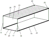
As shown in the attached figure 3, the structure of the lifting section is as follows: the lifting section is a cuboid or cylindrical or semi-cylindrical or elliptical cylindrical pipeline, a lifting wing panel 24 is arranged in an inner cavity 25 of the pipeline, an upper wall surface 26, a lower wall surface 16, a left wall surface 17 and a right wall surface 15 are respectively arranged on the pipeline walls corresponding to the upper, lower, left and right directions when the lifting wing panel 24 is horizontal, and the four wall surfaces are respectively connected through four rigid shafts 20.
The four wall surfaces of the lifting force section are all in a hollow mesh shape 23 or are completely open, so that the projections perpendicular to the upper surface and the lower surface of the lifting force wing panel 24 are communicated with the external atmospheric environment without being completely shielded, and the mutual balance of the internal forces of the system in the lifting force section is prevented.
The lifting wing panel 24 is a pressure-resistant air-impermeable plate made of aircraft material and having a wing profile. The length and width of the lifting wing panel 24 are less than or equal to the central axis section of the inner cavity 25 or the length and width of the lower wall surface 16, and the inner cavity 25 of the lifting section is spatially divided into two layers, or the lifting wing panel 24 and the lower wall surface 16 are overlapped and fused into a whole as shown in fig. 4.
Rectangular or arc-shaped air-tight rigid baffles 18 perpendicular to the edges are respectively arranged on the left edge 19 and the right edge 19 of the lifting wing panel 24, each baffle 18 is structurally symmetrical up and down by taking the left edge 19 and the right edge 19 as symmetry axes respectively, and is integrally H-shaped, or only has the upper half part or the lower half part of the H-shaped, and the function of blocking airflow from flowing from the high-pressure area on the lower surface of the lifting wing panel 24 to the low-pressure area on the upper surface of the lifting wing panel is achieved. The size of the baffle 18 at the left and right edges 19 can be a quarter of a circular arc of a cylinder with the lower surface of the lifting wing panel 24 as the central axis section or a rectangular chord of the arc, so that the whole lifting wing panel can rotate in the lifting section cavity 25.
The circular inner slide rail 21 is fixed on the inner wall surface of the lifting section, and the left edge 19 and the right edge 19 of the lifting wing panel 24 are fixed on the circular inner slide rail 21 through the left rotating shaft 22 and the right rotating shaft 22, so that the lifting wing panel 24 can perform pitching deflection around the inner cavity 25 in the radial direction through the rotating shafts 22, and the elevation angle of the lifting wing panel 24 can be changed in a reasonable range; meanwhile, the circular inner slide rail 21 can rotate clockwise and anticlockwise relative to the inner cavity 25 of the lift section in the axial direction, or the lift section is integrally fixed on the circular outer slide rail on the shell of the power device, so that the lift wing panel 24 can rotate clockwise and anticlockwise synchronously along with the whole lift section in the axial direction, and the lift force perpendicular to the lift wing panel 24 generates a yawing component.
The circular inner slide rail 21 and the rotary shaft 22 can be eliminated while simplifying the design. When the annular inner slide rail 21 is removed, the lift wing panel 24 can not rotate clockwise and anticlockwise around the axial direction of the lift wing panel relative to the inner cavity 25 of the lift section, at the moment, the left edge 19 and the right edge 19 of the lift wing panel 24 are directly fixed on the left wall surface 17 and the right wall surface 15 of the lift section, and the baffle 18 of the left edge 19 and the right edge 19 are respectively overlapped with the left wall surface 17 and the right wall surface 15 of the lift section and are fused into a whole; when the shaft 22 is eliminated, the lift wing panel 24 cannot pitch or yaw radially within the lift section cavity 25.
When the lifting section is a cuboid pipeline, the upper wall surface 26, the lower wall surface 16, the left wall surface 17 and the right wall surface 15 are rectangular surfaces, and the lifting wing panel 24 can be positioned between the upper wall surface 26 and the lower wall surface 16 or can be overlapped and fused with the lower wall surface 16; when the lifting section is a cylindrical or elliptical cylindrical pipeline, the upper wall surface 26, the lower wall surface 16, the left wall surface 17 and the right wall surface 15 are arc surfaces or elliptical arc surfaces, and the lifting wing panel 24 is positioned on the section of the central axis thereof; when the lifting section is a semi-cylindrical pipeline, the upper wall surface 26 is an arc surface, the lower wall surface 16 is a rectangular surface, the left wall surface 17 and the right wall surface 15 are eliminated, and the lifting wing panel 24 and the lower wall surface 16 are overlapped and fused into a whole. When the lifting wing panel 24 and the lower wall surface 16 are overlapped and integrated, the lifting wing panel 24 can be degenerated into a flat plate without wing profiles and fixed, and the annular inner slide rail 21 and the rotating shaft 22 are cancelled, namely, at the moment, the lifting wing panel 24 can not perform pitching deflection around the radial direction, and can not perform clockwise and anticlockwise rotation around the axial direction relative to the inner cavity 25 of the lifting section, at the moment, the baffle plates 18 on the left edge and the right edge 19 of the lifting wing panel 24 are respectively overlapped and integrated with the left wall surface 17 and the right wall surface 15 of the lifting section, the whole left wall surface 17 and the right wall surface 15 become the baffle plates 18, and under the condition, in order to weaken the disturbance of the external environment airflow to the lower surface of the lifting wing panel 24, airflow baffle plates and hollow mesh cover plates below the four baffle plates can be respectively arranged on the four edges of the lower.
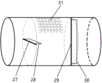
As shown in fig. five, the attitude control panel segment has the following structure: the attitude control panel section is a cylindrical or cuboid pipeline, and the inner space is communicated with the external atmospheric environment. The inner space is provided with a pressure-resistant, air-tight horizontal panel 28 and a vertical panel 30 which are independently deflectable and do not interfere with each other. If necessary, a honeycomb device and a damping net can be arranged at the airflow inlet of the attitude control panel section to play the role of smoothing the incoming flow. The horizontal panel 28 is positioned on a radial central transverse shaft 27 fixed on the left wall surface and the right wall surface, and the horizontal panel 28 can be controlled by an electronic control module and online upgradeable control software thereof to freely deflect up and down around the transverse shaft 27 through a steering engine according to sensor feedback data or manual control signals, so that the function of deflecting high-speed airflow to generate pitching moment is achieved; the vertical panel 30 is positioned on a central vertical shaft 29 which is fixed on the upper wall surface and the lower wall surface and is vertical to the radial direction, and the electronic control module and the on-line upgradable control software thereof can control the vertical panel 30 to freely deflect left and right around the vertical shaft 29 through the steering engine according to sensor feedback data or manual control signals, thereby playing the role of deflecting high-speed airflow to generate yawing moment. The parts of the air flow deflected by the attitude control panels, which act on the wall surface of the shell of the attitude control panel section, are provided with hollow meshes 31 or are open, so that the deflected air flow can directly act in the external atmospheric environment without being completely blocked. The attitude control panel section is divided into an attitude control panel section front section and an attitude control panel section rear section which are structurally in mirror symmetry, and the two sections can be mutually converted along with the change of the direction of high-speed airflow in the power device.
Fig. six is a schematic structural view of a typical embodiment of the power plant. One typical implementation is: the high-speed airflow can flow in a straight path with the minimum resistance, and finally directly acts on the atmospheric environment through the front section 32 of the attitude control panel section, the front high-speed airflow generating device 33, the lifting section 34, the rear high-speed airflow generating device 35 and the rear section 36 of the attitude control panel section which are connected in a seamless mode. And according to feedback data or manual control signals of the distributed sensors, the distributed sensors are regulated and controlled by an electronic control module and online upgradeable control software thereof. The battery is used as a direct energy source.
Based on the above exemplary embodiment, the power plant embodiment can be simplified as follows: the high-speed airflow sequentially flows through the front high-speed airflow generating device 33, the lifting section 34 and the rear section 36 of the attitude control panel section which are connected in a seamless mode, and finally acts on the atmospheric environment. Or the high-speed airflow sequentially flows through the lifting force section 34, the rear high-speed airflow generating device 35 and the rear section 36 of the attitude control panel section which are connected in a seamless mode, and finally directly acts on the atmospheric environment.
Based on the simplified embodiment, the embodiment of the power device can be further simplified as follows: the high-speed airflow sequentially flows through a front high-speed airflow generating device 33 and a lifting section 34 which are connected in a seamless mode, and finally, the high-speed airflow directly acts on the atmospheric environment; or the high-speed airflow flows through a lifting section 34 and a rear high-speed airflow generating device 35 which are connected seamlessly in sequence, and finally acts directly in the atmospheric environment. The airflow accelerating section of the high-speed airflow generating device only comprises a contraction pipe and does not comprise an expansion pipe, and the lifting force wing panel in the lifting force section 34 is overlapped and integrated with the lower wall surface of the lifting force section.
Based on the above several embodiments, the embodiments of the power device can be expanded as follows: under the condition that high-speed airflow generated and accelerated by the high-speed airflow generating devices 33 or 35 flows through the lifting wing panels in the lifting section 34 and the attitude control panels in the attitude control panel sections 32 or 36 in a straight path with minimum resistance and the upper and lower vertical projections of the lifting wing panels and the attitude control panels are not completely shielded from the external atmospheric environment, the plurality of high-speed airflow generating devices 33 or 35, the plurality of lifting sections 34 and the plurality of attitude control panel sections 32 or 36 are in straight seamless connection, or a group of controllable radial air injection air guide nozzles 37 or 38 are used as attitude adjustment modes, and a group of air guide pipes are used for blowing air to dissipate heat of a heating device and finally directly act on the atmospheric environment. One or more batteries are used as a direct energy source.
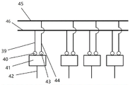
As shown in fig. seven, the electric connection between the electronic control modules of the power unit is schematically illustrated. Taking four identical electronic control modules as an example, the electrical connection method between the four identical electronic control modules is as follows: the communication interface 39 of the electronic control module 45 of each power unit in the power plant group is connected to the communication bus 41 through the communication line 40, so that mutual communication among all the power units is realized; the data interface 44 of each power unit is connected to the data bus 42 through the data line 43, and the electronic control module 45 of any power unit can acquire real-time data of any other power unit distributed sensor through the data bus 42 to realize data sharing; the electronic control module 45 of any power unit can be used as a main node, the main node issues a system-level regulation and control instruction to the communication bus 41 after being operated and processed by a processor and online upgradeable control software according to sensor data or received manual control signals obtained from the main node and the data bus 42, and each slave node analyzes the regulation and control instruction corresponding to the main node from the communication bus 41 and then sends a control signal to a control device such as an electronic speed regulator or a steering engine of the slave node through a control line, so that the running state of the slave node is regulated and controlled correspondingly. The main node regulates and controls the running state of each power unit in real time in parallel, so that the integral ordered and controllable running of the aircraft system is realized. And after the current master node fails, randomly allocating a slave node which normally operates as the master node.
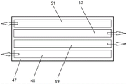
Fig. eight shows a schematic diagram of a typical application method of the power unit group on the novel aircraft, and the direction of an arrow parallel to the axial direction of the aircraft indicates the thrust direction of the power unit. Taking the combination of four identically configured power units as an example, a typical application method on a novel aircraft is as follows: the four power units are symmetrically arranged side by side in sequence on the same plane on the novel aircraft body 47 on two sides of a central axis passing through the center of gravity of the aircraft. The length of each power unit is the same as or close to the length of the fuselage of the novel aircraft system, so that the lift force generated by each power unit only generates a yawing moment on the gravity center of the aircraft system and does not generate a pitching moment.
The forces and moments experienced by aircraft systems are: the gravity of an aircraft system, the thrust of four power units, the lift of the four power units, the yaw moment of the lift of the four power units, which is respectively acted on the gravity center of the aircraft system, and the steering moment of the four power units, which is respectively acted on the gravity center of the aircraft system, are respectively acted on, or the yaw moment and the pitching moment of the attitude control panel in the power unit deflect airflow or the air guide nozzle jet air, which are respectively acted on the gravity center of the aircraft system, or the yaw moment of the lift section in the power unit, which is acted on the gravity center of the aircraft system. Setting the gravity value of an aircraft system as G, the thrust value of the first power unit 48 as T1, the lift value as L1, the steering moment of the thrust at the gravity center as Tfm1 and the yaw moment of the lift at the gravity center as Lfm 1; the thrust value of the second power unit 49 is T2, the lift value is L2, the steering moment of the thrust at the gravity center is Tfm2, and the yaw moment of the lift at the gravity center is Lfm 2; the thrust value of the third power unit 50 is T3, the lift value is L3, the steering moment of the thrust at the gravity center is Tfm3, and the yaw moment of the lift at the gravity center is Lfm 3; the fourth power unit 51 has a thrust value of T4, a lift value of L4, a steering moment of Tfm4 at the center of gravity of the thrust, and a yaw moment of Lfm4 at the center of gravity of the lift.
The control method comprises the following steps: in the state of balance of resultant force and resultant moment of an aircraft system, the thrust of the four power units is equal in magnitude: t1= T2= T3= T4, the thrust directions of the first power unit 48 and the fourth power unit 51 are the same, and are opposite to the thrust directions of the second power unit 49 and the third power unit 50, and the resultant forces of the four thrust forces are balanced: t1+ T4= T2+ T3; the resultant moment of the four thrusts on the center of gravity of the aircraft system is also balanced: tfm1+ Tfm3= Tfm2+ Tfm 4; the resultant moments of the four lift forces at the center of gravity of the aircraft system are also balanced: lfm1+ Lfm2= Lfm3+ Lfm 4; the combined lift force of the four power units is equal to the gravity of an aircraft system: g = L1+ L2+ L3+ L4; the rotational resultant torque of the electric fans of the first power unit 48 and the fourth power unit 51 is also balanced with the rotational resultant torque of the electric fans of the second power unit 49 and the third power unit 50; the moment of action of the airfoil or the air guide nozzle with the attitude adjusting function on the gravity center of the aircraft system is zero. The aircraft system remains airborne at this point.
The state of the aircraft system which is unbalanced horizontally and balanced vertically is divided into a forward or backward state, a maximum acceleration state, a maximum deceleration state, a pivot clockwise or counterclockwise steering state, a left yaw or right yaw state. At the moment, the magnitude of the combined lift force of the four power units is always equal to the magnitude of the gravity of the aircraft system.
In the forward state: t1+ T4> T2+ T3. The reverse is true in the fallback state: t1+ T4< T2+ T3.
In the maximum acceleration state, the four power units simultaneously provide forward thrust in the same direction as the speed of the aircraft by adjusting the steering of electric fans in the power units; when the electric fan is not adjustable in rotation direction, the rotation speed of the electric fan providing forward thrust can be increased, while the rotation speed of the electric fan providing reverse thrust is reduced until stopping.
In the maximum deceleration state, the four power units simultaneously provide reverse thrust opposite to the speed direction of the aircraft by adjusting the steering of the electric fans in the power units; when the electric fan is not adjustable in rotation direction, the rotation speed of the electric fan providing reverse thrust may be increased while the rotation speed of the electric fan providing forward thrust is decreased until stopped.
In the pivot clockwise steering state, the resultant force of the thrust forces is first kept in balance: t1+ T4= T2+ T3; the resultant moment of lift on the center of gravity is then balanced: l1> L4, L3> L2, Lfm1+ Lfm2= Lfm3+ Lfm 4; finally, the resultant moment of thrust on the center of gravity is unbalanced: t1> T4, T3> T2, Tfm1+ Tfm3> Tfm2+ Tfm 4. The original turning moment can be generated by the deflection of a vertical panel in the attitude control panel or the radial air injection of the air guide nozzle. And the control method of the pivot anticlockwise turning state and the like.
In the right yaw state, the resultant of the thrust forces is first kept in balance: t1+ T4= T2+ T3; the resultant moment of thrust on the center of gravity is then balanced: t1> T4, T2< T3, Tfm1+ Tfm3= Tfm2+ Tfm 4; finally, the resultant moment of the lift force on the gravity center is unbalanced: lfm1+ Lfm2> Lfm3+ Lfm 4. The yaw component can also be generated by rotating the lift wing panel in one or more power unit lift sections, thereby generating a yaw moment on the center of gravity of the aircraft system. The left yaw state control method and so on.
In a state where the aircraft system is horizontally balanced and vertically unbalanced, i.e., a vertically ascending or a vertically descending state. The resultant of the thrust forces of the four power units is zero at this time: t1+ T4= T2+ T3, and the resultant moment of the thrust of the four power units at the center of gravity of the aircraft system is zero: tfm1+ Tfm3= Tfm2+ Tfm4, the resultant moment of the four power unit lifts at the center of gravity of the aircraft system is zero: lfm1+ Lfm2= Lfm3+ Lfm4, the resultant moment of the panel or of the air nozzle with attitude adjustment function on the centre of gravity of the aircraft system is zero.
In the vertically raised state: l1+ L2+ L3+ L4> G. The vertical descending state is opposite: l1+ L2+ L3+ L4< G.
Two or more of the above-mentioned different states may constitute other flight states of the aircraft system, for example, a clockwise spiral ascent state is a clockwise state and a vertical ascent state, and so on.
The application method of the four power units on the novel aircraft can be equivalently replaced by the situation of using a combination of three power units. The four power units are respectively positioned at four corner positions of the plane and symmetrically distributed on the same plane of the novel aircraft, and the length of each power unit is smaller than half of the length of the fuselage of the novel aircraft system or does not cross the cross section where the gravity center of the aircraft system is positioned, so that the lift force generated by each power unit generates a yaw moment and a pitching moment on the gravity center of the aircraft system. It is also possible to extend to the case of a combination of more than four power units, for example, each of the four power units may be equivalently replaced with a plurality of power units. By referring to the control method, the aircraft system can be controlled to operate under the condition that the resultant force and resultant moment of the powered device are balanced or unbalanced.
Claims (9)
1. Rise, push away integrative power device, characterized by: the device consists of an air compression and rectification section, an air flow acceleration section, a lifting section, an attitude control panel section or an air guide spray pipe, a distributed sensor, an electronic control module and online upgradable control software thereof.
2. A power unit according to claim 1, further comprising: the air compression and rectification section, the air flow acceleration section, the lifting section and the attitude control panel section are in seamless connection; the high-speed airflow generating device consisting of the air compressing and rectifying section and the airflow accelerating section generates, rectifies and accelerates high-speed airflow, flows through a lifting wing panel in the lifting section and a horizontal panel and a vertical panel in the posture control panel section in a straight path with the minimum resistance, or part of the airflow is controllably sprayed out through an air guide spray pipe, and the part of the airflow blows and dissipates heat of a chip, a battery or other easily-heated devices through an air guide pipe and finally directly acts in an atmospheric environment; under the condition that the vertical projections of the lifting wing panel and the attitude control wing panel are communicated with the external atmospheric environment, the aircraft consists of one or more air compression and rectification sections, one or more airflow acceleration sections, one or more lifting sections, zero, one or more attitude control panel sections, zero, one or more attitude control air guide spray pipes, a plurality of distributed sensors, a plurality of electronic control modules and online upgradeable control software thereof; according to feedback data or manual control signals of the distributed sensors, the electronic control module and online upgradeable control software thereof regulate and control the output of force and moment; the battery is used as a direct energy source.
3. A power unit according to claim 1, further comprising: the air compression and rectification section is a cylindrical or tapered cylindrical pipeline, one or more electric fans inside the pipeline and a pipeline shell form a ducted fan or a centrifugal fan, an electronic speed regulator is arranged outside the pipeline, and one or more honeycombs and one or more damping nets are sequentially arranged inside the pipeline in a direction perpendicular to the axial direction.
4. A power unit according to claim 1, further comprising: the airflow accelerating section is formed by seamlessly connecting a contraction pipe with a smooth inner wall and an expansion pipe to form a Laval pipe or only comprises the contraction pipe.
5. A power unit according to claim 1, further comprising: the lifting section is a pipeline with an upper wall surface, a lower wall surface, a left wall surface and a right wall surface, and the wall surfaces are hollow net-shaped or open; a lifting wing panel is arranged in the inner cavity of the lifting section, is a pressure-resistant and air-impermeable plate with a wing shape, and divides the inner cavity space of the lifting section into an upper layer and a lower layer or is overlapped and fused with the lower wall surface of the lifting section into a whole; rectangular or arc-shaped air-tight rigid baffles perpendicular to the edges are respectively arranged on the left edge and the right edge of the lifting wing panel; when the inner wall surface of the lifting force section is fixed with the annular inner slide rail, the left edge and the right edge of the lifting force wing panel are fixed on the annular inner slide rail through the left rotating shaft and the right rotating shaft, otherwise, the left edge and the right edge are directly fixed on the inner wall surface of the lifting force section; the lifting wing panel can do pitching deflection around the lifting section through the rotating shaft in the radial direction and can also do clockwise and anticlockwise relative rotation around the lifting section through the annular inner sliding rail; the projections perpendicular to the upper and lower surfaces of the lifting wing panel are communicated with the external atmosphere without being completely shielded.
6. A power unit according to claim 1, further comprising: the attitude control panel section is a pipeline with an internal space communicated with the external atmospheric environment; the inner space is provided with a pressure-resistant airtight horizontal panel and a vertical panel which can independently operate and are not interfered with each other; the horizontal and vertical panels are located away from the center of gravity of the power plant or aircraft system; the air flow inlet is provided with a honeycomb device and a damping net.
7. The application method of the power device on the aircraft is characterized in that: the power devices are externally hung or integrated with the aircraft body, and provide thrust, lift force and attitude control moment for vertical take-off and landing flight and flight attitude control of the novel aircraft.
8. A method of use as claimed in claim 7, wherein: the resultant force of the non-zero thrust output by the power unit group formed by combining a plurality of power devices can be zero, the resultant force of the output non-zero lift force and the gravity of the aircraft can be zero, and the resultant moment of the output non-zero moment can be zero.
9. A method of use as claimed in claim 7, wherein: the communication lines of the electronic control modules of each power device are connected with each other through a communication bus, the data lines are connected with each other through a data bus, the electronic control modules are communicated with each other, share data and are master-slave nodes, the master node sends a control instruction to each power unit in parallel in real time, and the electronic control modules of each power unit and the online-upgradable control software thereof send control signals to the control device through the control lines according to the instruction.
Priority Applications (1)
| Application Number | Priority Date | Filing Date | Title |
|---|---|---|---|
| CN201811076919.3A CN110901896A (en) | 2018-09-14 | 2018-09-14 | Lifting and pushing integrated power device and application method thereof on aircraft |
Applications Claiming Priority (1)
| Application Number | Priority Date | Filing Date | Title |
|---|---|---|---|
| CN201811076919.3A CN110901896A (en) | 2018-09-14 | 2018-09-14 | Lifting and pushing integrated power device and application method thereof on aircraft |
Publications (1)
| Publication Number | Publication Date |
|---|---|
| CN110901896A true CN110901896A (en) | 2020-03-24 |
Family
ID=69812300
Family Applications (1)
| Application Number | Title | Priority Date | Filing Date |
|---|---|---|---|
| CN201811076919.3A Pending CN110901896A (en) | 2018-09-14 | 2018-09-14 | Lifting and pushing integrated power device and application method thereof on aircraft |
Country Status (1)
| Country | Link |
|---|---|
| CN (1) | CN110901896A (en) |
Cited By (2)
| Publication number | Priority date | Publication date | Assignee | Title |
|---|---|---|---|---|
| CN113200141A (en) * | 2021-05-26 | 2021-08-03 | 西安理工大学 | Suction type lift increasing device based on Laval tubular plasma |
| CN119088085A (en) * | 2024-08-21 | 2024-12-06 | 浙江大学 | A method of motion planning and fault-tolerant control of unmanned aerial vehicles facing power failure |
-
2018
- 2018-09-14 CN CN201811076919.3A patent/CN110901896A/en active Pending
Cited By (3)
| Publication number | Priority date | Publication date | Assignee | Title |
|---|---|---|---|---|
| CN113200141A (en) * | 2021-05-26 | 2021-08-03 | 西安理工大学 | Suction type lift increasing device based on Laval tubular plasma |
| CN113200141B (en) * | 2021-05-26 | 2022-05-31 | 西安理工大学 | A kind of air suction type increasing device based on Lava tubular plasma |
| CN119088085A (en) * | 2024-08-21 | 2024-12-06 | 浙江大学 | A method of motion planning and fault-tolerant control of unmanned aerial vehicles facing power failure |
Similar Documents
| Publication | Publication Date | Title |
|---|---|---|
| US12006030B2 (en) | Distributed electric propulsion modular wing aircraft with blown wing and extreme flaps for VTOL and/or STOL flight | |
| US10131426B2 (en) | Aircraft capable of vertical take-off | |
| US8733690B2 (en) | Lightweight vertical take-off and landing aircraft and flight control paradigm using thrust differentials | |
| JP5421503B2 (en) | Private aircraft | |
| CN106428548B (en) | A kind of vertical take-off and landing unmanned aerial vehicle | |
| US9487286B2 (en) | Lift and propulsion device, and heavier-than-air aircraft provided with such a device | |
| EP2991897B1 (en) | Vertical takeoff and landing (vtol) air vehicle | |
| US10287011B2 (en) | Air vehicle | |
| US9085355B2 (en) | Vertical takeoff and landing aircraft | |
| US20040149857A1 (en) | Ducted fan vehicles particularly useful as vtol aircraft | |
| CN113753229B (en) | Foldable fixed-wing four-rotor composite unmanned aerial vehicle and control method thereof | |
| CN112334386B (en) | Personal flying device with vertical take-off and landing | |
| RU141669U1 (en) | VERTICAL TAKEOFF AND LANDING FLIGHT | |
| US11186367B2 (en) | Multicopter with improved failsafe operation | |
| EP4337527B1 (en) | Aircraft | |
| RU2635431C1 (en) | Convertible aircraft | |
| US20040164203A1 (en) | Vertical take-off and landing aircraft | |
| RU2700154C1 (en) | Vertical take-off and landing aircraft | |
| CN108791876B (en) | Aircraft capable of vertically taking off and landing | |
| CN213200096U (en) | Ducted fan unmanned aerial vehicle | |
| CN110901896A (en) | Lifting and pushing integrated power device and application method thereof on aircraft | |
| WO2004031876A1 (en) | Flight control system for vtol aircraft | |
| CN114275156B (en) | Thrust vector unmanned vehicles based on duct fan | |
| CN113104195B (en) | Double-duct composite wing aircraft | |
| CN113415416A (en) | Aircraft and control method thereof |
Legal Events
| Date | Code | Title | Description |
|---|---|---|---|
| PB01 | Publication | ||
| PB01 | Publication | ||
| SE01 | Entry into force of request for substantive examination | ||
| SE01 | Entry into force of request for substantive examination | ||
| WD01 | Invention patent application deemed withdrawn after publication | ||
| WD01 | Invention patent application deemed withdrawn after publication |
Application publication date: 20200324 |