CN110901981A - Triangle-shaped mechanism of ribbon instrument - Google Patents

Triangle-shaped mechanism of ribbon instrument Download PDF

Info

Publication number
CN110901981A
CN110901981A CN201911168883.6A CN201911168883A CN110901981A CN 110901981 A CN110901981 A CN 110901981A CN 201911168883 A CN201911168883 A CN 201911168883A CN 110901981 A CN110901981 A CN 110901981A
Authority
CN
China
Prior art keywords
cable tie
cylinder
pulling
head
tool according
Prior art date
Legal status (The legal status is an assumption and is not a legal conclusion. Google has not performed a legal analysis and makes no representation as to the accuracy of the status listed.)
Granted
Application number
CN201911168883.6A
Other languages
Chinese (zh)
Other versions
CN110901981B (en
Inventor
许修义
Current Assignee (The listed assignees may be inaccurate. Google has not performed a legal analysis and makes no representation or warranty as to the accuracy of the list.)
Shenzhen Shi Weide Automation Technology Co ltd
Original Assignee
Shenzhen Shi Weide Automation Technology Co Ltd
Priority date (The priority date is an assumption and is not a legal conclusion. Google has not performed a legal analysis and makes no representation as to the accuracy of the date listed.)
Filing date
Publication date
Application filed by Shenzhen Shi Weide Automation Technology Co Ltd filed Critical Shenzhen Shi Weide Automation Technology Co Ltd
Priority to CN201911168883.6A priority Critical patent/CN110901981B/en
Publication of CN110901981A publication Critical patent/CN110901981A/en
Application granted granted Critical
Publication of CN110901981B publication Critical patent/CN110901981B/en
Active legal-status Critical Current
Anticipated expiration legal-status Critical

Links

Images

Classifications

    • BPERFORMING OPERATIONS; TRANSPORTING
    • B65CONVEYING; PACKING; STORING; HANDLING THIN OR FILAMENTARY MATERIAL
    • B65BMACHINES, APPARATUS OR DEVICES FOR, OR METHODS OF, PACKAGING ARTICLES OR MATERIALS; UNPACKING
    • B65B13/00Bundling articles
    • B65B13/02Applying and securing binding material around articles or groups of articles, e.g. using strings, wires, strips, bands or tapes
    • B65B13/04Applying and securing binding material around articles or groups of articles, e.g. using strings, wires, strips, bands or tapes with means for guiding the binding material around the articles prior to severing from supply

Landscapes

  • Engineering & Computer Science (AREA)
  • Mechanical Engineering (AREA)
  • Basic Packing Technique (AREA)

Abstract

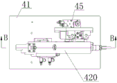
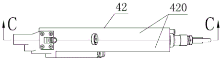
本发明提供了一种扎带工具的三角形机构,包括:自动扎带工作头本体、穿拉切组合模块、抬头气缸、升降气缸、升降滑块;所述升降气缸固定在所述自动扎带工作头本体上并与所述升降滑块连接,所述抬头气缸安装在所述升降滑块上,所述抬头气缸的作用杆通过铰链与所述穿拉切组合模块连接,所述升降气缸作用杆通过所述升降滑块采用铰链与所述穿拉切组合模块连接,所述抬头气缸、所述升降滑块及所述穿拉切组合模块装配后形成三角形的三条边;所述的一种扎带工具的三角形机构实现所述穿拉切组合模块的复合运动、实现扎带工具的多个导向爪按顺序关联动作。

Figure 201911168883

The invention provides a triangular mechanism of a tie tool, comprising: an automatic tie working head body, a pulling and cutting combined module, a head-up cylinder, a lifting cylinder, and a lifting slider; the lifting cylinder is fixed on the automatic tie and works The head body is connected with the lifting slide block, the lift cylinder is installed on the lift slide block, the action rod of the lift cylinder is connected with the thread-pulling and cutting combination module through a hinge, and the lift cylinder action rod The lifting slider is connected with the pulling and cutting combined module by a hinge, and the head-up cylinder, the lifting slider and the pulling and cutting combined module are assembled to form three sides of a triangle; The triangular mechanism with the tool realizes the compound movement of the threading, pulling and cutting combined module, and realizes the sequential associated actions of the plurality of guide claws of the tie tool.

Figure 201911168883

Description

Triangle-shaped mechanism of ribbon instrument
Technical Field
The invention relates to a movement mechanism, in particular to a triangular mechanism of a ribbon binding tool.
Background
Traditionally, bundling of ribbon is accomplished by hand, 2011 since, desktop formula automatic ribbon binding machine appeared in domestic market, i also developed handheld automatic ribbon binding tool in 2012 and 2013, abroad had handheld automatic ribbon binding rifle that uses disjunctor ribbon, but aforementioned various automatic ribbon binding machines and automatic ribbon binding tools are all unsuitable to be used in narrow space ribbon operation and need pass through the ribbon operation of aperture, for example: the bundling of the motor coils is the condition of typical narrow and small space operation, each motor stator coil needs to bundle 4-12 ribbons to prevent the coils from loosening in work, the bundling operation of the motor coils is manual operation in the world, the working efficiency is low, the labor intensity is high, various automatic ribbon devices which are already published cannot solve the technical problem of the automatic ribbon operation of the narrow and small space of the motor coils, even if the claw of a handheld automatic ribbon tool designed by the user is specially miniaturized and transformed, self-locking can be formed after bundling, and the bundled coils are difficult to take out. Many engineers in the electrical machine industry have thought of many solutions for bundling stator coils of electrical machines, such as: some designs to adopt the pneumatics or electronic take-up, and cut off the device of ribbon afterbody, but still need in advance the manual ribbon of taking, the manual ribbon of wearing, and manual pretension, and this kind of pneumatics or electronic device is adopted by motor industry generally, but this kind of device does not realize automatic fundamentally, and efficiency improves a little. According to the requirements of a plurality of large-scale factories in the motor industry, after a long-time conception, the inventor specially develops an automatic cable-tying method and a tool for the cable-tying operation of a motor coil in a narrow space, and a triangular mechanism of the cable-tying tool is one of key parts of the automatic cable-tying method and the tool.
Disclosure of Invention
The invention aims to solve the problems that various automatic band binding devices and tools in the market can not realize automatic band binding operation in a narrow space of a motor coil, and research and develop a brand-new automatic band binding method and parts of the tools.
An automatic tie tool comprising: the automatic binding machine comprises a host, a feeding pipe, a data line and an automatic binding tape working head, wherein the host is connected with the feeding pipe and the data line respectively and is connected with the automatic binding tape working head through the feeding pipe and the data line; furthermore, the automatic binding tape working head comprises an automatic binding tape working head body, a penetrating, pulling and cutting combined module, a fixed second guide claw, a movable second guide claw cylinder, a head raising cylinder, a lifting cylinder and a lifting slide block; the fixed second guide claw, the movable second guide claw cylinder and the lifting cylinder are fixed on the automatic binding tape working head body, and the movable second guide claw is connected with an action rod of the movable second guide claw cylinder and can slide in a guide groove of the automatic binding tape working head body.
The invention is realized by the following technical scheme: a triangular mechanism of a tie tool, comprising: the automatic binding work head comprises an automatic binding work head body, a penetrating, drawing and cutting combined module, a head raising cylinder, a lifting cylinder and a lifting slide block; the lifting cylinder is fixed on the automatic binding tape working head body and connected with the lifting slide block, the head raising cylinder is installed on the lifting slide block through a hinge, an action rod of the head raising cylinder is connected with the penetrating and drawing combined module through a hinge, the lifting cylinder action rod passes through the lifting slide block, the lifting slide block is connected with the penetrating and drawing combined module through a hinge (the lifting slide block is actually an extension part of the lifting cylinder action rod), and the head raising cylinder, the lifting slide block and the penetrating and drawing combined module form three triangular edges after being assembled.
Further, the penetration, drawing and cutting combined module is provided with: the device comprises a shell, a support plate, a motor, a reduction gearbox, a counting gear sensor, a connecting rod, a cutter, a fixed first guide claw, a movable first guide claw, an internal feeding pipe and a belt pulling mechanism. The reduction gearbox, the counting gear sensor, the connecting rod, the fixed first guide claw, the movable first guide claw and the belt pulling mechanism are all arranged on the support plate;
the power output of the reduction gearbox is transmitted to the counting gear, a counting gear sensor is arranged on one side of the counting gear and fixed on the support plate, and the counting gear sensor senses once when the counting gear rotates to a certain fixed position.
The strap mechanism is provided with: the device comprises a frame, a cover plate, a belt pulling gear, a belt pulling shaft and a belt pulling wheel; the belt drawing gear, the belt drawing shaft and the belt drawing wheel are arranged on the rack and the cover plate through bearings; the periphery of the strap wheel is provided with ratchets, the ratchets of the strap wheel bite the strap and continuously tension the strap, and the tail of the strap is cut off by the cutter after the strap is tensioned.
Further, a cavity is arranged in the frame, and the drawstring wheel is accommodated in the cavity; the frame has still designed ribbon waste material passageway, ribbon waste material passageway is the ribbon import in the one end that links to each other with the second guide pawl, and the other end is the ribbon export, frame and apron will transmission systems such as stretching strap gear, count gear and reducing gear box keep apart outside ribbon waste material passageway, prevent ribbon piece that produces in the ribbon waste material passageway get into transmission system.
The invention has the beneficial effects that:
1. the compound movement of the penetration, drawing and cutting combined module is realized by adopting a compound mechanism in triangular connection;
2. the triangular-connected composite mechanism realizes sequential and correlated actions of a plurality of guide claws of the ribbon tool;
3. the trouble that the manual binding belt is used for low efficiency since the motor is born is solved;
4. the difficult problem of automatic ribbon in little space is solved.
[ description of the drawings ]
FIG. 1 is an isometric view of an automatic tie;
FIG. 2 is a front view of the automatic band-binding head with the protective cover removed, the movable second guide claw at the bottom dead center position, the lift cylinder and the raising cylinder at the top dead center position, and with the automatic band-binding head in this state, the work piece is put in and taken out;
FIG. 3 is a top view of the automatic tie head with the protective cover removed;
FIG. 4 is a front view of the automatic cable tie workhead with the protective cover removed, the movable second guide pawl and the lift cylinder at the top dead center position, the lift cylinder at the bottom dead center position, and the cable tie positioned by the automatic cable tie workhead fed with the cable tie when the automatic cable tie workhead is in this state;
FIG. 5 is a sectional view taken along line B-B of FIG. 3, with the movable second guide pawl, the lift cylinder and the raising cylinder all in the bottom dead center position just after the strapping operation is completed;
FIG. 6 is a front view of the automatic tie head with the protective cover removed; the movable second guide claw and the lifting cylinder are positioned at the top dead center position, and the head-up cylinder is positioned at the bottom dead center position; the second guide claw cylinder, the lifting cylinder and the head-up cylinder are represented by a simplified schematic diagram, and the triangular structural relationship among the head-up cylinder, the lifting slide block and the penetration, drawing and cutting combined module is shown;
FIG. 7 is a front view of an automatic cable tie workhead, illustrated in simplified schematic form: the lifting slide block is actually the extension part of the lifting cylinder action rod, and simultaneously indicates that: the head raising cylinder, the lifting slide block and the penetrating, drawing and cutting combined module are in a triangular structural relationship;
FIG. 8 is a top view of a die cut through die;
FIG. 9 is a front view of the die cut through combination with one of the housings removed;
FIG. 10 is a cross-sectional view of a through stretch-cut segmented module C-C;
FIG. 11 is an isometric view of the through stretch-cut combination module with one of the housings removed;
reference numerals: 1. a host; 112. an electrical control system; 2. a feed pipe; 3. a data line; 4. an automatic band binding working head; 41. an automatic band binding working head body; 42. penetrating, drawing and cutting the combined module; 420. a housing; 421. a mounting plate; 422. a motor; 423. a reduction gearbox; 424. a counting gear; 425. a counting gear sensor; 429. a connecting rod; 4210. a torque comparator; 4211. a cutter; 4212. a fixed first guide jaw; 4213. a movable first guide claw; 4214. an internal feed tube; 4215. a belt pulling mechanism; 42150. a frame; 42151. a cover plate; 421500, a pull belt gear; 421511, a pull tape shaft; 421500, a belt-pulling wheel; 42156. a fixed second guide jaw; 42157. a movable second guide claw; 43. A movable second guide claw cylinder; 44. a head raising cylinder; 45. a lifting cylinder; 46. a lifting slide block; 47. and (4) a hinge.
[ detailed description ] embodiments
The invention is further described with reference to the accompanying drawings and the detailed description:
example 1
As shown in figure 1, the automatic binding tape working head 4 is connected with the main machine 1 through a flexible feeding pipe 2 with an inner hole with a square section and a data line 3, and the height and the direction of the automatic binding tape working head 4 can be adjusted according to the height and the direction of a motor stator production line under the condition that the main machine 1 is fixed.
Example 2
As shown in fig. 2, 3, 4, 5, 6 and 7, the automatic band head 4 comprises an automatic band head body 41, a through-pull-cut combination module 42, a fixed second guide claw 42156, a movable second guide claw 42157, a movable second guide claw cylinder 43, a head raising cylinder 44, a lifting cylinder 45 and a lifting slider 46, wherein the fixed second guide claw 42156, the movable second guide claw cylinder 43 and the lifting cylinder 45 are fixed on the automatic band head body 41, and the movable second guide claw 42157 is coupled with the action rod of the movable second guide claw cylinder 43 and can slide in the guide groove of the automatic band head body 41.
Example 3
As shown in fig. 2, 3, 4, 5, 6, 7, a triangular mechanism of a tie tool includes: the automatic binding band working head comprises an automatic binding band working head body 41, a penetrating, drawing and cutting combined module 42, a head raising cylinder 44, a lifting cylinder 45 and a lifting slide block 46; the lifting cylinder 45 is installed on the automatic binding tape working head body 41 and connected with the lifting slide block 46, the head raising cylinder 44 is installed on the lifting slide block 46 through a hinge 47, an action rod of the head raising cylinder 44 is connected with the penetration, drawing and cutting combined module 42 through the hinge 47, an action rod of the lifting cylinder 45 is connected with the penetration, drawing and cutting combined module 42 through the lifting slide block 46 through the hinge 47, and the head raising cylinder 44, the lifting slide block 46 and the penetration, drawing and cutting combined module 42 form three triangular sides after being assembled.
Example 4
As shown in fig. 2 to 11, the piercing-drawing-cutting combination module 42 is provided with: the counting mechanism comprises a shell 420, a support plate 421, a motor 422, a reduction box 423, a counting gear 424, a counting gear sensor 425, a connecting rod 429, a cutter 4211, a fixed first guide claw 4212, a movable first guide claw 4213, an inner feeding pipe 4214 and a pull belt mechanism 4215, wherein the reduction box 423, the counting gear 424, the counting gear sensor 425, the connecting rod 429, the cutter 4211, the fixed first guide claw 4212, the movable first guide claw 4213 and the pull belt mechanism 4215 are all arranged on the support plate 421;
one side of the reduction box 423 is connected with a counting gear 424, the power output of the reduction box 423 is transmitted to the counting gear 424, one side of the counting gear 424 is provided with a counting gear sensor 425, the counting gear sensor 425 is fixed on the support plate 421, the counting gear sensor 425 senses once when the counting gear 424 rotates to a certain fixed position, the electric control system 112 immediately controls the motor 422 to stop, namely, the counting gear 424 rotates for one circle in each working period;
further, a data line 3 and a flexible feeding pipe 2 are connected to the end of the shell 420, the flexible feeding pipe 2 is connected with an inner feeding pipe 4214, and the inner feeding pipe 4214 is connected with a frame 42150 of the belt pulling mechanism 4215;
as shown in fig. 5, 9 and 10, the strap mechanism 4215 includes a frame 42150, a cover 42151, a strap gear 421500, a strap shaft 421511 and a strap wheel 421522, the strap gear 421500, the strap shaft 421511 and the strap wheel 421522 are mounted on the frame 42150 and the cover 42151 through bearings, external power is transmitted by the strap gear 421500, the strap shaft 421511 and the strap wheel 421522 are driven to rotate, and teeth of a strap are engaged by ratchets of the strap wheel 421522.
The frame 42150, the fixed first guide claw 4212, the fixed second guide claw 42156 and the movable second guide claw 42157 are all provided with guide grooves, the movable first guide claw 4213 and the fixed first guide claw 4212 are combined to form the guide grooves, the frame 42150 and the cover plate 42151 are also provided with pits for positioning the head of the binding belt, the head of the binding belt is blocked and cannot back up when pushed to move the pit position by compressed air, the frame 42150, the fixed first guide claw 4212, the movable first guide claw 4213, the fixed second guide claw 42156 and the guide grooves of the movable second guide claw 42157 are butted to form a guide groove closing ring which is approximately pear-shaped, the circumference of the guide groove closing ring is larger than the length of the binding belt, when the binding belt is pushed into the guide groove closing ring to be positioned, the root of the movable second guide claw 42157 locks the head, the movable first guide claw 4213 hooks 429 inwards under the action of a connecting rod 429, the tail of the cable tie is inserted into a hole in the head of the cable tie, the movable first guide claw 4213 pushes the tail of the cable tie into a gap between the pull belt wheels 421522, ratchet wheels on the periphery of the pull belt wheel 421522 bite the cable tie to continuously tighten the cable tie, a cutter 4211 is arranged below the right side of the rack 42150, the cutter 4211 cuts off the tail of the cable tie under the action of external power after the cable tie is tightened, and the pull belt wheel 421522 continuously rotates to roll out the cut tail of the cable tie.
Further, a cavity is formed in the rack 42150, the strap wheel 421522 is accommodated in the cavity, a strap waste channel is further designed in the rack 42150, the strap waste channel is formed in the way that one end, connected with the second guide claw, of the rack 42150 is a strap inlet, the other end (the upper side shown in fig. 5) is a strap outlet, the rack 42150 and the cover plate 42151 isolate the strap gear 421500 and the transmission system outside the strap waste channel, and strap scraps generated in the strap waste channel are prevented from entering the transmission system.
Further, the belt pulling mechanism 4215 is further provided with an air pipe 42155, the air pipe 42155 is fixed on the cover plate 42151, an obtuse angle is formed between the air pipe 42155 and the outlet of the belt waste channel, the air pipe 42155 is used for blowing out the cut belt waste and the cut scrap, and due to the effect of the obtuse angle, the air flow meets the surface of the rack 42150 in the belt waste channel and flows to the outlet along the surface by utilizing the 'surface effect' of the aerodynamic air flow, and the belt tailing and the cut scrap cut by the cutter 4211 are blown out of the belt waste channel.
Example 5:
as shown in fig. 2, the lifting cylinder 45 and the raising cylinder 44 are both at the top dead center position, the penetration, pulling and cutting combined module 42 is at the highest position and raises, the motor stator is placed in the automatic band-binding working head 4, the fixed second guide claw 42156 is inserted into the gap between the silicon steel sheet and the coil, and the foot switch is stepped on; as shown in fig. 4, when the head raising cylinder 44 is operated to the bottom dead center, the penetrating, pulling and cutting combination module 42 swings downwards, the frame 42150, the fixed first guide claw 4212, the movable first guide claw 4213, the fixed second guide claw 42156 and the guide groove of the movable second guide claw 42157 are butted to form a guide groove closed loop, the band passes through the feed pipe 2 and the inner feed pipe 4214 under the pushing action of compressed air, the band head is finally sent to the pit of the frame 42150 for positioning, the movable first guide claw 4213 hooks inwards under the action of the connecting rod 429 to penetrate the band tail into the hole of the band head, the movable first guide claw 4213 pushes the band tail into the gap between the pulling pulley 421522, and the ratchet wheel at the periphery of the pulling pulley 421522 bites the band to continuously tighten the band; as shown in fig. 5, the movable second guide jaw cylinder 43 moves downward and drives the movable second guide jaw 42157 to move to the bottom dead center, and the lift cylinder 45 also moves downward and leftward immediately, and drives the lift slider 46, the pull-through cut-off module 42, and the head-up cylinder 44 to move downward and leftward to the bottom dead center, and the lift slider 46, the pull-through cut-off module 42, and the head-up cylinder 44 to move downward and leftward together have two purposes: firstly, the tie is tensioned by the penetrating, pulling and cutting combined module 42, and secondly, the head of the tied tie is moved to the center of the motor stator, so that the interference between the head of the tie and a motor shell is avoided during the subsequent assembly of the motor stator; the lifting cylinder 45 moves towards the left lower side and drives the lifting slide block 46, the penetrating, drawing and cutting combined module 42 and the head raising cylinder 44 to move towards the left lower side to a lower dead point;
as described in connection with example 4: the power of the motor 422 is transmitted to the drawing belt gear 421500 through the reduction gearbox 423 and the counting gear 424, so that the coil of the belt can be continuously tightened, when the coil of the belt is tightened and a set pre-tightening force is reached, the cutter 4211 cuts off the tail of the belt, after the tail of the belt is cut off, the drawing belt gear 421500 continuously rotates to roll out the cut tail of the belt, the air pipe 42155 and the outlet direction of a belt waste channel formed by the frame 42150 and the cover plate 42151 form an obtuse angle, and the cut tail of the belt is accelerated to be ejected outwards under the action of compressed air guided by the air pipe 42155.
As shown in fig. 2, after the automatic band-binding workhead 4 finishes the actions of penetrating, pulling and cutting the band, the lifting cylinder 45, the head raising cylinder 44 and the movable second guide claw cylinder 43 all reset to the top dead center position, so that the bundled motor stator is convenient to take out.
Appropriate changes and modifications to the embodiments described above will become apparent to those skilled in the art from the disclosure and teachings of the foregoing description. Therefore, the present invention is not limited to the specific embodiments disclosed and described above, and some modifications and variations of the present invention should fall within the scope of the claims of the present invention. Furthermore, although specific terms are employed herein, they are used in a generic and descriptive sense only and not for purposes of limitation.

Claims (10)

1.一种扎带工具的三角形机构,其特征在于:包括:自动扎带工作头本体、穿拉切组合模块、抬头气缸、升降气缸、升降滑块;所述升降气缸固定在所述自动扎带工作头本体上并与所述升降滑块连接,所述抬头气缸安装在所述升降滑块上,所述抬头气缸、所述升降滑块及所述穿拉切组合模块装配后形成三角形的三条边。1. A triangular mechanism of a cable tie tool, characterized in that: it comprises: an automatic cable tie working head body, a pull-and-cut combination module, a head-up cylinder, a lift cylinder, and a lift slider; the lift cylinder is fixed on the automatic cable tie. The main body of the belt working head is connected with the lifting slide block, the lift cylinder is installed on the lift slide block, and the lift cylinder, the lift slide block and the pull-cut combination module are assembled to form a triangular shape. three sides. 2.根据权利要求1所述的一种扎带工具的三角形机构,其特征在于:所述抬头气缸的作用杆通过铰链与所述穿拉切组合模块连接。2 . The triangular mechanism of a cable tie tool according to claim 1 , wherein the action rod of the head-up cylinder is connected to the thread-pull-cut combination module through a hinge. 3 . 3.根据权利要求1所述的一种扎带工具的三角形机构,其特征在于:所述升降滑块通过铰链与所述穿拉切组合模块连接。3 . The triangular mechanism of a cable tie tool according to claim 1 , wherein the lifting slider is connected to the pulling-cutting combination module through a hinge. 4 . 4.根据权利要求1所述的一种扎带工具的三角形机构,其特征在于:所述抬头气缸通过铰链安装在所述升降滑块上。4 . The triangular mechanism of a cable tie tool according to claim 1 , wherein the head-up cylinder is mounted on the lifting slider through a hinge. 5 . 5.根据权利要求1所述的一种扎带工具的三角形机构,其特征在于:所述穿拉切组合模块至少设置有:壳体、马达、减速箱、计数齿轮、计数齿轮感应器、切刀、固定的第一导向爪、可动的第一导向爪、内部送料管、拉带机构。5 . The triangular mechanism of a cable tie tool according to claim 1 , wherein the piercing, pulling and cutting combined module is at least provided with: a casing, a motor, a reduction box, a counting gear, a counting gear sensor, a cutting A knife, a fixed first guide claw, a movable first guide claw, an internal feeding tube, and a belt pulling mechanism. 6.根据权利要求5所述的一种扎带工具的三角形机构,其特征在于:所述拉带机构至少设置有:机架、盖板、拉带齿轮、拉带轮;所述拉带齿轮及拉带轮通过轴承安装在所述机架及盖板上。6 . The triangular mechanism of a cable tie tool according to claim 5 , wherein the belt pulling mechanism is at least provided with: a frame, a cover plate, a pulling belt gear, and a pulling pulley; the pulling belt gear The pulley and the pulley are mounted on the frame and the cover plate through bearings. 7.根据权利要求6所述的一种扎带工具的三角形机构,其特征在于:所述拉带轮的周边设计有棘齿。7 . The triangular mechanism of a cable tie tool according to claim 6 , wherein a ratchet tooth is designed on the periphery of the pulley. 8 . 8.根据权利要求6所述的一种扎带工具的三角形机构,其特征在于:所述机架内设有容纳拉带轮的空腔。8 . The triangular mechanism of a cable tie tool according to claim 6 , wherein the frame is provided with a cavity for accommodating the pulley. 9 . 9.根据权利要求6所述的一种扎带工具的三角形机构,其特征在于:所述机架还设计有扎带废料通道。9 . The triangular mechanism of a cable tie tool according to claim 6 , wherein the frame is further designed with a cable tie waste channel. 10 . 10.根据权利要求5所述的一种扎带工具的三角形机构,其特征在于:所述的可动的第一导向爪与所述的固定的第一导向爪组合形成导向槽。10 . The triangular mechanism of a cable tie tool according to claim 5 , wherein the movable first guide claw and the fixed first guide claw are combined to form a guide groove. 11 .
CN201911168883.6A 2016-01-04 2016-01-04 Tool for automatic ribbon binding in narrow space Active CN110901981B (en)

Priority Applications (1)

Application Number Priority Date Filing Date Title
CN201911168883.6A CN110901981B (en) 2016-01-04 2016-01-04 Tool for automatic ribbon binding in narrow space

Applications Claiming Priority (2)

Application Number Priority Date Filing Date Title
CN201610005704.7A CN105460260B (en) 2016-01-04 2016-01-04 A tool for automatic cable ties in narrow spaces
CN201911168883.6A CN110901981B (en) 2016-01-04 2016-01-04 Tool for automatic ribbon binding in narrow space

Related Parent Applications (1)

Application Number Title Priority Date Filing Date
CN201610005704.7A Division CN105460260B (en) 2016-01-04 2016-01-04 A tool for automatic cable ties in narrow spaces

Publications (2)

Publication Number Publication Date
CN110901981A true CN110901981A (en) 2020-03-24
CN110901981B CN110901981B (en) 2021-10-12

Family

ID=55598515

Family Applications (4)

Application Number Title Priority Date Filing Date
CN201911233520.6A Withdrawn CN110901982A (en) 2016-01-04 2016-01-04 Combined guide claw mechanism of automatic binding tool
CN201610005704.7A Active CN105460260B (en) 2016-01-04 2016-01-04 A tool for automatic cable ties in narrow spaces
CN201911168883.6A Active CN110901981B (en) 2016-01-04 2016-01-04 Tool for automatic ribbon binding in narrow space
CN201911262017.3A Withdrawn CN110901983A (en) 2016-01-04 2016-01-04 Four-guide-claw combined mechanism of binding tape tool

Family Applications Before (2)

Application Number Title Priority Date Filing Date
CN201911233520.6A Withdrawn CN110901982A (en) 2016-01-04 2016-01-04 Combined guide claw mechanism of automatic binding tool
CN201610005704.7A Active CN105460260B (en) 2016-01-04 2016-01-04 A tool for automatic cable ties in narrow spaces

Family Applications After (1)

Application Number Title Priority Date Filing Date
CN201911262017.3A Withdrawn CN110901983A (en) 2016-01-04 2016-01-04 Four-guide-claw combined mechanism of binding tape tool

Country Status (1)

Country Link
CN (4) CN110901982A (en)

Cited By (1)

* Cited by examiner, † Cited by third party
Publication number Priority date Publication date Assignee Title
CN114524122A (en) * 2022-03-03 2022-05-24 吉安跃辉自动化设备有限公司 Automatic hand-held gun for binding belt

Families Citing this family (13)

* Cited by examiner, † Cited by third party
Publication number Priority date Publication date Assignee Title
CN107539521B (en) * 2016-06-27 2019-11-12 沈阳新松机器人自动化股份有限公司 A kind of harness automatic bonding unit
CN106742456A (en) * 2017-01-06 2017-05-31 深圳市众和正通科技发展有限公司 One kind ties up device for mark automatically
CN107098014B (en) * 2017-07-04 2020-05-26 深圳市施威德自动化科技有限公司 Automatic material distributing and counting device for bulk binding tapes
CN116119134B (en) * 2017-07-04 2025-02-18 深圳市施威德自动化科技有限公司 Automatic cutting device for conjoined ribbon
CN116336176A (en) * 2017-09-03 2023-06-27 深圳市施威德自动化科技有限公司 Three-terminal input/output mechanism of automatic ribbon tool
CN108507423A (en) * 2017-11-29 2018-09-07 昆明德澳科技有限公司 A kind of detonator storing material collecting device
CN109051124B (en) * 2018-06-15 2020-12-08 宁波禹泰自动化科技有限公司 A junction box automatic tying equipment
CN108945564B (en) * 2018-08-27 2024-06-25 深圳市施威德自动化科技有限公司 Working head of automatic cable tie tool
DE102021203997A1 (en) * 2021-04-21 2022-10-27 Hellermanntyton Gmbh Cable tie straightening device
CN113561414B (en) * 2021-09-26 2021-12-07 南通凌志环保科技有限公司 Automatic material distribution equipment for bulk binding tapes
CN115072030B (en) * 2022-07-11 2024-04-26 深圳市施威德自动化科技有限公司 Shaping and locking mechanism of automatic bundling tool and bundling tool
CN117302624A (en) * 2023-09-06 2023-12-29 苏州市毅田自动化科技有限公司 An automatic tie-tying machine
CN117326125A (en) * 2023-09-06 2024-01-02 苏州市毅田自动化科技有限公司 Automatic wire winding ribbon equipment

Family Cites Families (15)

* Cited by examiner, † Cited by third party
Publication number Priority date Publication date Assignee Title
JPS6121316A (en) * 1984-07-10 1986-01-30 株式会社 ニフコ Bundling tool
DE3632239A1 (en) * 1986-09-23 1988-04-07 Messerschmitt Boelkow Blohm DEVICE FOR ATTACHING CABLE TIES WITH A MOTOR DRIVEN TIE DEVICE
JPH08151011A (en) * 1994-11-30 1996-06-11 Mitsuba Seisakusho:Kk Automatic binding machine
JP2923242B2 (en) * 1996-03-15 1999-07-26 大木樹脂工業株式会社 Rebar binding machine
DE29617651U1 (en) * 1996-10-10 1998-02-05 Paul Hellermann GmbH, 25421 Pinneberg Arrangement for binding an object, in particular a wire harness
JP3949177B2 (en) * 1997-07-29 2007-07-25 トーマス アンド ベッツ インターナショナル,インク. Improved cable tie distributor
JP2009154895A (en) * 2007-12-26 2009-07-16 Max Co Ltd Binding machine for horticulture
CN105173166B (en) * 2008-04-23 2019-01-04 信诺国际Ip控股有限责任公司 Mobile strapping device
CN102390606B (en) * 2011-07-22 2013-09-25 孙激扬 Steel bar bundling mechanical hand and special buckle element thereof
CN104853591B (en) * 2012-11-29 2017-07-21 日绊株式会社 Binding apparatus
CN104150006B (en) * 2013-09-02 2016-09-14 许修义 A kind of hand-held automatic tie tool
CN204433117U (en) * 2015-02-06 2015-07-01 张家港市兰马机械有限公司 A kind of ribbon feeder
CN204822147U (en) * 2015-08-03 2015-12-02 深圳市林全科技有限公司 Full -automatic ribbon of hand -held type machine
CN105059581B (en) * 2015-08-11 2018-06-01 许修义 A belt-drawing mechanism of an automatic cable tie tool
CN205819628U (en) * 2016-01-04 2016-12-21 深圳市施威德自动化科技有限公司 A kind of instrument for small space automatic tie

Cited By (1)

* Cited by examiner, † Cited by third party
Publication number Priority date Publication date Assignee Title
CN114524122A (en) * 2022-03-03 2022-05-24 吉安跃辉自动化设备有限公司 Automatic hand-held gun for binding belt

Also Published As

Publication number Publication date
CN105460260B (en) 2019-11-22
CN110901982A (en) 2020-03-24
CN110901981B (en) 2021-10-12
CN110901983A (en) 2020-03-24
CN105460260A (en) 2016-04-06

Similar Documents

Publication Publication Date Title
CN110901981A (en) Triangle-shaped mechanism of ribbon instrument
CA2694202C (en) Strapping machine with improved tension, seal and feed arrangement
CN108945564B (en) Working head of automatic cable tie tool
CN105059581B (en) A belt-drawing mechanism of an automatic cable tie tool
KR20110028657A (en) Portable electric binding device
US20240376728A1 (en) Binding machine
CN210191911U (en) Online electric wire binding apparatus
CN205819628U (en) A kind of instrument for small space automatic tie
CN111591490B (en) A cable tie machine
CN219786420U (en) Cable fixed length cutting device
GB1198135A (en) Wire Tensioning and Tying Device
CN214608247U (en) Steel band bundling machine with bundling head and steel band biting device
CN220948688U (en) Packaging equipment
JP2018109294A (en) Binding machine
CN113597925A (en) A cord reel for a binding machine and a binding machine with the cord reel
CN223891271U (en) Full-automatic ribbon installation aircraft nose module
CN204747087U (en) Wire drawing coiling mechanism
CN210724500U (en) Winding device for motor manufacturing
CN221715536U (en) A cutting device for wire rope processing
CN112024780A (en) Automatic reinforcing bar of business turn over material is cut and is tied up equipment
CN218913523U (en) Labor-saving clutch structure of motorcycle engine
CN214930877U (en) Belt feeding and guiding device of belt binding machine
CN221835904U (en) Wire harness strap pulling and cutting mechanism
CN210238140U (en) Traction device for cutting and pressing steel wire rope
CN214280718U (en) Electric wire poling draw gear

Legal Events

Date Code Title Description
PB01 Publication
PB01 Publication
SE01 Entry into force of request for substantive examination
GR01 Patent grant
GR01 Patent grant
CP03 Change of name, title or address

Address after: No. 405, Building A, Fuhai Technology Industrial Park, Huafeng Zhigu, Xinhe Community, Fuhai Street, Bao'an District, Shenzhen City, Guangdong Province 518101

Patentee after: SHENZHEN SHI WEIDE AUTOMATION TECHNOLOGY Co.,Ltd.

Country or region after: China

Address before: 518103 Zhuoke Science Park, 190 Chongqing Road, Heping Community, Fuhai Street, Baoan District, Shenzhen City, Guangdong Province

Patentee before: SHENZHEN SHI WEIDE AUTOMATION TECHNOLOGY Co.,Ltd.

Country or region before: China

CP03 Change of name, title or address
EE01 Entry into force of recordation of patent licensing contract

Application publication date: 20200324

Assignee: Foshan Aobangli Technology Co.,Ltd.

Assignor: SHENZHEN SHI WEIDE AUTOMATION TECHNOLOGY Co.,Ltd.

Contract record no.: X2025980000544

Denomination of invention: A tool for automatic zip ties in narrow spaces

Granted publication date: 20211012

License type: Common License

Record date: 20250107

EE01 Entry into force of recordation of patent licensing contract