CN111053473A - Intelligent stirrer - Google Patents
Intelligent stirrer Download PDFInfo
- Publication number
- CN111053473A CN111053473A CN201911257127.0A CN201911257127A CN111053473A CN 111053473 A CN111053473 A CN 111053473A CN 201911257127 A CN201911257127 A CN 201911257127A CN 111053473 A CN111053473 A CN 111053473A
- Authority
- CN
- China
- Prior art keywords
- main body
- blade
- food
- support
- motor
- Prior art date
- Legal status (The legal status is an assumption and is not a legal conclusion. Google has not performed a legal analysis and makes no representation as to the accuracy of the status listed.)
- Pending
Links
- 235000013305 food Nutrition 0.000 claims abstract description 140
- 238000003780 insertion Methods 0.000 claims description 48
- 230000037431 insertion Effects 0.000 claims description 48
- 238000002156 mixing Methods 0.000 claims description 14
- 238000000034 method Methods 0.000 claims description 10
- 238000010298 pulverizing process Methods 0.000 description 17
- 230000005484 gravity Effects 0.000 description 15
- 238000010168 coupling process Methods 0.000 description 14
- 238000005859 coupling reaction Methods 0.000 description 14
- 230000008878 coupling Effects 0.000 description 13
- 238000003825 pressing Methods 0.000 description 8
- 238000001179 sorption measurement Methods 0.000 description 7
- 238000010586 diagram Methods 0.000 description 6
- 230000015572 biosynthetic process Effects 0.000 description 5
- 239000013013 elastic material Substances 0.000 description 5
- 230000008569 process Effects 0.000 description 5
- 230000005611 electricity Effects 0.000 description 4
- 230000003139 buffering effect Effects 0.000 description 3
- 238000005259 measurement Methods 0.000 description 3
- 230000004048 modification Effects 0.000 description 3
- 238000012986 modification Methods 0.000 description 3
- 230000008859 change Effects 0.000 description 2
- 238000010276 construction Methods 0.000 description 2
- 230000000694 effects Effects 0.000 description 2
- 230000005489 elastic deformation Effects 0.000 description 1
- 239000000463 material Substances 0.000 description 1
- 239000002184 metal Substances 0.000 description 1
- 238000011017 operating method Methods 0.000 description 1
- 239000004033 plastic Substances 0.000 description 1
Images




Classifications
-
- A—HUMAN NECESSITIES
- A47—FURNITURE; DOMESTIC ARTICLES OR APPLIANCES; COFFEE MILLS; SPICE MILLS; SUCTION CLEANERS IN GENERAL
- A47J—KITCHEN EQUIPMENT; COFFEE MILLS; SPICE MILLS; APPARATUS FOR MAKING BEVERAGES
- A47J43/00—Implements for preparing or holding food, not provided for in other groups of this subclass
- A47J43/04—Machines for domestic use not covered elsewhere, e.g. for grinding, mixing, stirring, kneading, emulsifying, whipping or beating foodstuffs, e.g. power-driven
- A47J43/07—Parts or details, e.g. mixing tools, whipping tools
- A47J43/0716—Parts or details, e.g. mixing tools, whipping tools for machines with tools driven from the lower side
-
- A—HUMAN NECESSITIES
- A47—FURNITURE; DOMESTIC ARTICLES OR APPLIANCES; COFFEE MILLS; SPICE MILLS; SUCTION CLEANERS IN GENERAL
- A47J—KITCHEN EQUIPMENT; COFFEE MILLS; SPICE MILLS; APPARATUS FOR MAKING BEVERAGES
- A47J43/00—Implements for preparing or holding food, not provided for in other groups of this subclass
- A47J43/04—Machines for domestic use not covered elsewhere, e.g. for grinding, mixing, stirring, kneading, emulsifying, whipping or beating foodstuffs, e.g. power-driven
- A47J43/046—Machines for domestic use not covered elsewhere, e.g. for grinding, mixing, stirring, kneading, emulsifying, whipping or beating foodstuffs, e.g. power-driven with tools driven from the bottom side
-
- A—HUMAN NECESSITIES
- A47—FURNITURE; DOMESTIC ARTICLES OR APPLIANCES; COFFEE MILLS; SPICE MILLS; SUCTION CLEANERS IN GENERAL
- A47J—KITCHEN EQUIPMENT; COFFEE MILLS; SPICE MILLS; APPARATUS FOR MAKING BEVERAGES
- A47J43/00—Implements for preparing or holding food, not provided for in other groups of this subclass
- A47J43/04—Machines for domestic use not covered elsewhere, e.g. for grinding, mixing, stirring, kneading, emulsifying, whipping or beating foodstuffs, e.g. power-driven
- A47J43/07—Parts or details, e.g. mixing tools, whipping tools
-
- A—HUMAN NECESSITIES
- A47—FURNITURE; DOMESTIC ARTICLES OR APPLIANCES; COFFEE MILLS; SPICE MILLS; SUCTION CLEANERS IN GENERAL
- A47J—KITCHEN EQUIPMENT; COFFEE MILLS; SPICE MILLS; APPARATUS FOR MAKING BEVERAGES
- A47J43/00—Implements for preparing or holding food, not provided for in other groups of this subclass
- A47J43/04—Machines for domestic use not covered elsewhere, e.g. for grinding, mixing, stirring, kneading, emulsifying, whipping or beating foodstuffs, e.g. power-driven
- A47J43/07—Parts or details, e.g. mixing tools, whipping tools
- A47J43/08—Driving mechanisms
-
- A—HUMAN NECESSITIES
- A47—FURNITURE; DOMESTIC ARTICLES OR APPLIANCES; COFFEE MILLS; SPICE MILLS; SUCTION CLEANERS IN GENERAL
- A47J—KITCHEN EQUIPMENT; COFFEE MILLS; SPICE MILLS; APPARATUS FOR MAKING BEVERAGES
- A47J43/00—Implements for preparing or holding food, not provided for in other groups of this subclass
- A47J43/04—Machines for domestic use not covered elsewhere, e.g. for grinding, mixing, stirring, kneading, emulsifying, whipping or beating foodstuffs, e.g. power-driven
- A47J43/07—Parts or details, e.g. mixing tools, whipping tools
- A47J43/08—Driving mechanisms
- A47J43/085—Driving mechanisms for machines with tools driven from the lower side
Landscapes
- Engineering & Computer Science (AREA)
- Mechanical Engineering (AREA)
- Food Science & Technology (AREA)
- Food-Manufacturing Devices (AREA)
- General Preparation And Processing Of Foods (AREA)
Abstract
The intelligent stirrer crushes or mixes the food accommodated in the inner part through the rotating blade, and is characterized in that if the stirrer is inclined by external force and then the external force is removed, the intelligent stirrer mixes the food accommodated in the inner part while repeatedly shaking in the left-right direction.
Description
Technical Field
The application is divided into patent applications with application date of 2015, 12 and 16, application number of 201580066637.3 and title of 'intelligent stirrer and working method thereof'.
The present invention relates to a blender, and more particularly, to an intelligent blender capable of uniformly mixing and/or pulverizing food received inside the blender.
Background
In general, a blender mixes and/or pulverizes food by rotating an electric motor by power supply and rotating a blade, that is, a pulverizing blade, by the electric motor.
However, since the conventional blender rotates with the position of the pulverizing blade fixed in a predetermined manner, after pulverizing for a predetermined time, the food is arranged on the outer periphery of the pulverizing blade by the centrifugal force of the pulverizing blade or the like.
Therefore, in order to crush food that has not been crushed, a user must hold the mixer and shake or apply an impact to the mixer to move the food disposed on the outer periphery to a position having the crushing blades.
As described above, since the agitator is held to be shaken or an impact is applied, a user may not use the agitator, and the agitator may be damaged due to a strong impact applied thereto.
Also, in the case where the agitator is large, it is difficult to hold the agitator and shake.
Furthermore, in the case where the content such as food is not well pulverized, the motor is occasionally rotated at a very high speed, and therefore, the life of the motor may be shortened and the electricity charge may be increased.
Disclosure of Invention
Technical problem
The present invention has been made to solve the above problems, and an object of the present invention is to provide an intelligent mixer: the agitator is repeatedly shaken in the left-right direction to continuously mix the food, thereby making the pulverization better, and also simply shaking the large agitator.
Another object of the present invention is to provide an intelligent mixer, comprising: as the pulsator is repeatedly rotated in the up and down direction, the food is continuously and uniformly mixed, so that the pulverization is better performed, and the mixing and the pulverization are well performed, thereby extending the life of the motor and reducing electricity charges.
Another object of the present invention is to provide an intelligent mixer and a method for operating the same, comprising: the stirrer is arranged obliquely in the left-right direction with respect to the vertical line, so that the food can be mixed and pulverized better.
Means for solving the problems
In order to achieve the above object, the present invention provides an intelligent mixer for crushing or mixing food accommodated therein by a rotating blade, wherein when the mixer is tilted by an external force and then the external force is removed, the food accommodated therein is mixed while being repeatedly shaken in the left-right direction.
The above-mentioned agitator includes: a body having a motor built therein; a receiving part combined with the upper part of the body for receiving food; and a blade mounted to the body or the container and rotating by the motor to crush or mix food, wherein the center of gravity of the pulsator is located at a position from a half of the total vertical length to a lower side, and a lower surface of the body contacting the bottom surface has a circular shape.
The lower surface of the body is formed in a dome shape protruding downward.
Alternatively, the above-mentioned agitator includes: a body having a motor built therein; a receiving part combined with the upper part of the body for receiving food; the blade, which is mounted on the body or the containing part and is rotated by the motor to crush or mix food; a first bracket disposed at a lower portion of the body; and a connecting member for connecting the first bracket to the main body, wherein the connecting member allows the main body to swing in a left-right direction with respect to the first bracket when the main body receives an external force.
The connecting member is formed of an elastic material that elastically recovers when an external force is removed after the elastic deformation of the connecting member is applied, one end of the connecting member is coupled to the first bracket, and the other end of the connecting member is coupled to the body.
The connecting member is formed of a coil spring arranged in the vertical direction.
One end of the connecting member is coupled to an upper surface of the first bracket, and the other end is coupled to a lower surface of the main body, so that the main body stands and supports with respect to the first bracket in a free state.
The connecting member is elastically compressed by an external force pressing the accommodating portion.
The first bracket is provided with a limiting block for limiting the angle of the body swinging along the left-right direction.
At this time, the connecting member is elastically compressed in the vertical direction by an external force pressing the accommodating portion.
Alternatively, the above-mentioned agitator includes: a body having a motor built therein; a receiving part combined with the upper part of the body for receiving food; the blade, which is mounted on the body or the containing part and is rotated by the motor to crush or mix food; a second bracket disposed in a lateral direction of the body; and a rotation shaft rotatably connected to the second bracket, the rotation shaft being positioned above a center of gravity of the combined body and the accommodating unit, the body and the accommodating unit being swung in a left-right direction with reference to the rotation shaft when an external force is applied to the body and the accommodating unit.
Alternatively, in order to achieve the above object, an intelligent mixer according to the present invention is an intelligent mixer for crushing or mixing food accommodated therein by a rotating blade, the intelligent mixer comprising: a body having a motor built therein; a receiving part combined with the upper part of the body for receiving food; the blade, which is mounted on the body or the containing part and is rotated by the motor to crush or mix food; and a third bracket coupled to a lower portion of the body, the lower portion of the body being coupled to the third bracket in such a manner as to be inclined with respect to the third bracket when an external force is applied thereto.
The lower part of the body is combined with the third bracket through a ball joint.
A dome-shaped insertion protrusion is formed to protrude from a lower portion of the body, and an insertion groove that is rotated by insertion of the insertion protrusion is formed at an upper portion of the third bracket.
In this case, it is preferable that a fixing groove is formed in the insertion protrusion, and a fixing protrusion to be inserted into the fixing groove is formed in the third bracket in a protruding manner, and the main body is maintained in the state by inserting the fixing protrusion into the fixing groove.
A rotary protrusion having a dome shape and a gear is formed at a lower portion of the body, a driving motor is mounted to the third bracket, the driving motor is engaged with the rotary protrusion gear, and the body is tilted with respect to the third bracket by rotation of the rotary protrusion engaged with the driving motor.
In order to achieve the above object, an intelligent mixer according to the present invention is an intelligent mixer for pulverizing or mixing food accommodated therein by a rotating blade, the intelligent mixer comprising: a body having a motor built therein; a receiving part combined with the body for receiving food; a blade mounted on the body or the container and rotating by the motor to crush or mix food; a base part disposed at a lower part of the body; and a driving unit disposed between the base unit and the body, and supporting the body in a vertical direction with respect to the base unit, wherein the driving unit supports the body so as to move the body in a vertical direction or a horizontal direction with respect to the base unit, and the food contained in the containing unit is mixed as the body is moved in the vertical direction or the horizontal direction by the driving unit.
The driving part is made of elastic material which can be elastically restored when the external force is removed after the driving part is elastically deformed by the external force, one end of the driving part is connected with the base part, and the other end of the driving part is connected with the main body.
The driving part is formed by a coil spring, the lower end of the driving part is combined with the upper surface of the base part, and the upper end of the driving part is combined with the upper surface of the body.
The base part is formed of an adsorption plate and is tightly fixed to the bottom surface.
The present invention may further include a hinge portion that is coupled to the body so as to be rotatable in a vertical direction with respect to the base portion, wherein the driving portion supports the body so that the body moves in the vertical direction with respect to the base portion about the hinge portion, and the food stored in the storage portion is mixed as the body rotates in the vertical direction about the hinge portion.
The driving part is formed of a spring, one end of the spring is coupled to the base part, and the other end of the spring is coupled to the body, and the body is repeatedly rotated in the vertical direction around the hinge part by an elastic restoring force of the spring by an external force.
In this case, the spring is formed of a coil spring, and has a lower end coupled to an upper surface of the base portion and an upper end coupled to a lower surface of the body.
Alternatively, the driving part may be formed of an electrically variable member whose length is changed by a power source, one end of the electrically variable member may be in contact with the base part, and the other end of the electrically variable member may be in contact with the main body, and the main body may be repeatedly rotated in a vertical direction about the hinge part by the change in length of the electrically variable member.
The lower end of the electrically variable member is hinged to the upper surface of the base part, and the upper end is hinged to the lower surface of the body.
A torsion spring is mounted on the hinge portion to elastically support the main body in the vertical direction relative to the base portion.
The lower surface of the base portion is coupled to the suction plate.
The food mixing device further includes a hinge portion that is coupled to the body so as to be rotatable in a vertical direction with respect to the base portion, and the driving portion supports the body so as to move in the vertical direction with respect to the base portion about the hinge portion, and mixes the food contained in the containing portion as the body rotates in a horizontal direction about the hinge portion.
In order to achieve the above object, an intelligent mixer according to the present invention is an intelligent mixer for pulverizing or mixing food accommodated therein by a rotating blade, the intelligent mixer comprising: a body in which a first motor is built; a receiving part detachably coupled to an upper part of the body and receiving food therein; a blade mounted inside the accommodating part and rotating by the first motor to crush or mix food; a support part rotatably combined with and supporting the main body; and an inclined forming portion, wherein the main body is arranged to be inclined with respect to the support portion, and the main body and the receiving portion are arranged to be inclined with respect to the support portion by the inclined forming portion.
The inclination forming part includes a driving part for rotating the body so as to incline the body in a vertical direction, and the body is arranged to be inclined with respect to the support part by the operation of the driving part.
The driving unit is formed by a second motor.
The inclined forming part further includes: a drive gear attached to the second motor; and a driven gear coupled to a lower portion of the body and engaged with the driving gear, wherein the body is tilted with respect to the support portion while the driven gear is moved by rotation of the driving gear by the second motor.
The invention also includes: a measuring section for detecting rotation data of the blade; and a control unit for controlling the operation of the driving unit, wherein when the rotation state of the blade detected by the measuring unit exceeds a preset reference range, the control unit operates the driving unit so that the main body is disposed to be inclined with respect to the support unit.
The measuring section detects a rotational speed of the blade, and the control section operates the driving section such that the main body is disposed to be inclined with respect to the support section when the rotational speed of the blade detected by the measuring section is higher than a preset reference speed.
The measuring unit detects a torque of the first motor for rotating the blade, and the control unit operates the driving unit such that the main body is disposed to be inclined with respect to the support unit when the torque of the blade detected by the measuring unit is smaller than a predetermined reference torque.
The measuring section detects a current value applied to the first motor, the first motor rotates the blade, and the control section operates the driving section such that the main body is disposed to be inclined with respect to the support section when the current value detected in the measuring section is smaller than a predetermined reference current value.
The present invention further includes a timer for driving the driving unit at predetermined intervals.
The body is repeatedly swung in the left-right direction with respect to the support portion by the operation of the driving portion.
The inclination forming portion may maintain the main body in an inclined state by forming the main body at a predetermined angle with respect to the support portion.
The support part supports the main body by being hinged with the lower part of the main body, and the inclined forming part is mounted on the hinge joint part of the main body and the support part so as to maintain the inclined state of the main body relative to the support part.
Alternatively, the support portion includes: a support plate disposed at a lower portion of the body; and a support protrusion protruding upward from the support plate, wherein a side portion of the body is hinge-coupled to the support protrusion, an elastic member is disposed between a lower portion of the body and the support plate to elastically support the body upward, the inclined formation portion is mounted at a hinge coupling portion of the body and the support protrusion to maintain a state in which the body is inclined with respect to the support portion, and a stop state maintaining force of the body by the inclined formation portion is greater than an elastic force of the elastic member.
The inclined forming part includes: a locking member mounted on one of the body and the support portion and having a plurality of locking grooves formed therein; and an engagement adjusting member which is attached to the remaining one of the main body and the support portion and is inserted into the engagement groove, and when the main body is rotated, the engagement adjusting member is inserted into the engagement groove to maintain the main body and the accommodating portion in an inclined state.
The locking adjustment member is formed of a plate spring having a locking protrusion formed thereon.
Alternatively, the locking adjustment member includes: a ball member inserted into the locking groove; and a spring elastically supporting the ball member along the direction of the locking groove.
A dome-shaped insertion protrusion is formed to protrude from a lower portion of the body, an insertion groove is formed in an upper portion of the support portion to be rotated by insertion of the insertion protrusion, and when the body is rotated, the insertion protrusion is rotated inside the insertion groove and the inclined formation portion maintains a rotated state.
The inclined forming part is formed by the outer circumference of the insertion protrusion and the inner circumference of the insertion groove which are contacted with each other, and the body maintains the inclined state by the friction generated by the contact between the outer circumference of the insertion protrusion and the inner circumference of the insertion groove.
Alternatively, the inclined forming portion includes: a fixing groove formed on the insertion protrusion; and a fixing protrusion protruding from the support portion and inserted into the fixing groove, wherein the fixing protrusion is inserted into the fixing groove to maintain the body in its state.
The inclination forming part includes a driving motor for rotating the main body with respect to the support part, and the main body maintains an inclined state when the driving motor is stopped.
In addition, in the operating method of the intelligent mixer according to the present invention, the intelligent mixer includes: a body in which a first motor is built; a receiving part detachably coupled to an upper part of the body and receiving food therein; a blade mounted inside the accommodating part and rotating by the first motor to crush or mix food; a support part rotatably hinged with the main body to support the main body; and an inclined forming part, which makes the main body incline relative to the support part, wherein the main body and the containing part are arranged in a state of inclining relative to the support part at least 2 degrees by the inclined forming part, and the food is crushed or mixed by the rotation of the blade.
ADVANTAGEOUS EFFECTS OF INVENTION
The intelligent mixer of the present invention as described above has the following effects.
In the present invention, if the external force is removed after the mixer is tilted by the external force, the mixer repeatedly shakes in the left-right direction, so that the food contained in the mixer is mixed and well pulverized.
Therefore, there is a convenience in that a user does not need to continuously hold the agitator to perform shaking or to apply impact.
That is, in the present invention, if a user tilts and releases the pulsator once, the pulsator continuously shakes like a tumbler, a swing, or the like, and thus the user does not need to continuously hold the pulsator to shake.
And, in case the mixer is large, the mixer can be held to shake easily and gently, thereby facilitating mixing and crushing of the food.
In the present invention, as the body rotates in the vertical direction about the hinge portion, the food contained in the containing portion can be uniformly mixed and well pulverized.
Therefore, the user does not need to continuously hold the agitator to shake or apply impact, and can have the convenience of the user, and prevent the damage of the motor.
Further, since the contents such as food are mixed and pulverized well, it is not necessary to rotate the motor at a very high speed instantaneously, and the life of the motor can be extended and the electricity consumption can be reduced, which is very economical.
Also, in the case of using the coil spring as the driving part, the coil spring also plays a role of buffering, and noise and vibration generated in the body, which are transmitted to the bottom surface, can be minimized.
In the present invention, the pulsator may be inclined by an external force, and thus, the food contained in the pulsator may be mixed and well pulverized.
Therefore, there is a convenience that a user does not need to hold the agitator continuously and shake or apply an impact.
Further, the agitator is automatically tilted by the second motor, the measuring section, the control section, and the like, and thus can be conveniently used.
Drawings
Fig. 1 is a sectional structural view of an intelligent mixer according to a first embodiment of the present invention.
Fig. 2a to 2d are diagrams illustrating a state of use of the intelligent mixer according to the first embodiment of the present invention.
Fig. 3 is a sectional structural view of an intelligent mixer according to a second embodiment of the present invention.
Fig. 4a to 4d are views illustrating a state of use of the intelligent mixer according to the second embodiment of the present invention.
Fig. 5a to 5b are a perspective view and a sectional view of an intelligent mixer according to a third embodiment of the present invention.
Fig. 6a to 6d are views illustrating a state of use of the intelligent mixer according to the third embodiment of the present invention.
Fig. 7 is a sectional structural view of an intelligent mixer according to a fourth embodiment of the present invention.
Fig. 8a to 8d are views illustrating a state of use of the intelligent mixer according to the fourth embodiment of the present invention.
Fig. 9 is a sectional structural view of an intelligent mixer according to a fifth embodiment of the present invention.
Fig. 10 is a sectional structural view of an intelligent mixer according to a sixth embodiment of the present invention.
Fig. 11a to 11d are operation diagrams of an intelligent mixer according to a sixth embodiment of the present invention.
Fig. 12 is a sectional structural view of an intelligent mixer according to a sixth embodiment of a modification of the present invention.
Fig. 13 is a perspective view of an intelligent mixer according to a seventh embodiment of the present invention.
Fig. 14 is a sectional structural view of an intelligent mixer according to a seventh embodiment of the present invention.
Fig. 15a to 15d are operation diagrams of an intelligent mixer according to a seventh embodiment of the present invention.
Fig. 16a to 16d are sectional views illustrating an operation of an intelligent mixer according to an eighth embodiment of the present invention.
Fig. 17a to 17d are sectional views showing the construction of an intelligent mixer according to a ninth embodiment of the present invention.
Fig. 18 is a perspective view of a pulsator according to a tenth embodiment of the present invention.
Fig. 19 is a sectional structural view taken along line a-a' of fig. 18 and viewed in accordance with the present invention.
Fig. 20 is a structural view of a pulsator according to a tenth embodiment of the present invention.
Fig. 21a to 21d are views illustrating an operation of a pulsator according to a tenth embodiment of the present invention.
Fig. 22 is an exploded perspective view of a pulsator according to an eleventh embodiment of the present invention.
Fig. 23 is a sectional structural view of a stirrer according to an eleventh embodiment of the present invention.
Fig. 24a to 24d are operation diagrams of a stirrer according to an eleventh embodiment of the present invention.
Fig. 25 is a perspective view of a mixer according to a twelfth embodiment of the present invention.
FIG. 26 is a sectional view showing a mixer according to a twelfth embodiment of the present invention.
Fig. 27a to 27d are views illustrating an operation of a pulsator according to a twelfth embodiment of the present invention.
Fig. 28 is a sectional structural view of a stirrer according to a thirteenth embodiment of the present invention.
Fig. 29a to 29d are views illustrating an operation of a pulsator according to a thirteenth embodiment of the present invention.
Detailed Description
First embodiment
Fig. 1 is a sectional structural view of an intelligent mixer according to a first embodiment of the present invention, and fig. 2a to 2d are views illustrating a state of use of the intelligent mixer according to the first embodiment of the present invention.
The present invention relates to a blender for pulverizing and/or mixing food 150 accommodated inside by a rotating blade 130, wherein if the blender is tilted by an external force and then the external force is removed, the food 150 accommodated inside is mixed while being repeatedly shaken in the left-right direction.
To this end, in the first embodiment, the mixer includes a body 110, a receiving portion 120, and a blade 130.
The body 110 has a motor 111 therein.
In this case, the motor 111 may be operated by an external power source, or may be wirelessly operated by charging a built-in battery.
The lower surface of the body 110 contacting the bottom surface is circular.
The lower surface of the body 110 may be rounded in one direction, but may be preferably rounded in a dome shape protruding downward.
Therefore, the body 110 may be inclined with respect to the bottom surface in any one of the front, rear, left, and right directions.
The receiving part 120 is coupled to an upper portion of the body 110, and receives food 150 therein.
The storage section 120 may be the same as that used in a conventionally known mixer.
For example, the receiving portion 120 may include an upper cup member, generally formed in the shape of "∩", as in the present embodiment, and a pad member coupled to a lower portion of the upper cup member for closing the lower portion of the upper cup member.
The pad member is detachably coupled to the upper surface of the body 110.
The blade 130 is attached to the body 110 or the receiving part 120, and the motor 111 rotates to crush and/or mix the food 150.
In this embodiment, the blade 130 is attached to the pad member of the receiving portion 120.
The blade 130 is coupled to the motor 111 and rotated by the rotation of the motor 111.
In the present invention, the center of gravity of the agitator is located at a position from half to the lower side of the total vertical length, and preferably, is located adjacent to the lower surface of the main body 110.
Therefore, when the agitator is inclined, the agitator is repeatedly shaken in the left-right direction by the center of gravity as if it were a tumbler and is automatically stopped.
The state of use of the present invention formed with the above structure will be described below.
As shown in fig. 2a, food 150 is put into the receiving part 120.
At this time, the mixer is caused to stand in the vertical direction.
As shown in fig. 2b, when the blade 130 is rotated by the operation of the motor 111, a part of the food 150 is crushed and pushed to the vicinity of the inner wall of the receiving part 120 by a centrifugal force.
Therefore, the food 150 has a portion that is not crushed by the blade 130.
At this time, the user strikes the agitator in the horizontal direction.
Thus, as shown in fig. 2c, the agitator inclined in one direction by the external force moves again in the other direction in which the center of gravity is located as the external force is removed.
At this time, as shown in fig. 2d, the agitator may be tilted in the other direction by an inertial force moving in the other direction.
Therefore, as shown in fig. 2c and 2d, the stirrer oscillates like a tumbler by repeating the tilting operation.
Therefore, as the receiving part 120 becomes longer, the food 150 pushed to the vicinity of the inner wall of the receiving part 120 is inclined again toward the center of the blade 130 by gravity.
As described above, the pulsator is repeatedly shaken and inclined in the horizontal direction, and food 150, which is not yet pulverized, can be more effectively pulverized by the blade 130 as the food 150 moves toward the center of the blade 130.
In the present invention, when a user strikes the mixer once, the mixer automatically repeats tilting a plurality of times in the left-right direction, and there is no need to continuously shake or strike the mixer strongly in order to move the food 150 moving toward the inner wall of the storage unit 120 toward the center of the blade 130.
This invention is more effective in crushing the food 150 with less moisture.
Second embodiment
Fig. 3 is a sectional structural view of an intelligent mixer according to a second embodiment of the present invention, and fig. 4a to 4d are views illustrating a state of use of the intelligent mixer according to the second embodiment of the present invention.
The mixer of the second embodiment includes a body 110, a receiving portion 120, a blade 130, a first bracket 141, and a connecting member 112.
The body 110, the receiving portion 120, and the blade 130 are the same as those of the first embodiment, and detailed descriptions thereof will be omitted.
In this embodiment, as in the first embodiment, the lower surface of the body 110 may be in a dome shape, or may be in a flat shape.
The first bracket 141 is disposed at a lower portion of the body 110.
That is, in the second embodiment, the lower surface of the body 110 is not in contact with the bottom surface, and the lower surface of the first bracket 141 is in contact with the bottom surface.
Further, an adsorption plate 1 (not shown) or the like is attached to the first bracket 141 so as to be fixed to the bottom surface, so that the first bracket 141 is not shaken.
A stopper 141a for limiting a swing angle of the body 110 in the left-right direction is formed at the first bracket 141.
Therefore, when the body 110 swings in the left-right direction, the body 110 contacts the stopper 141a to prevent the body 110 from swinging at an excessive angle.
The connection member 112 connects the first bracket 141 to the body 110.
When the connection member 112 receives an external force, the body 110 is swung in the left-right direction with reference to the first bracket 141.
The connection member 112 may be configured to allow the body 110 to swing in the left-right direction with respect to the first bracket 141.
In particular, the connection member 112 is formed of an elastic material that elastically restores when the external force is removed after being elastically deformed by the external force, and preferably has one end coupled to the first bracket 141 and the other end coupled to the body 110.
As described above, since the connection member 112 is made of an elastic material, when the main body 110 is inclined by an external force, the elastic member is also elastically deformed, and when the external force is removed, the main body 110 is swung in the left-right direction by the elastic restoring force of the elastic member.
As described above, the connection member 112 is made of a material having elasticity, and a plate spring, a wire spring, or the like can be used.
One end of the connection member 112 formed of the coil spring is coupled to an upper surface of the first bracket 141 and the other end is coupled to a lower surface of the body 110, and the body 110 is supported in a free state in a standing manner with respect to the first bracket 141.
In particular, the connection member 112 is formed of a coil spring having an elastic force, and when an external force is applied, strong shaking due to an inertial force may be generated, thereby allowing the foods and the like received in the receiving part 120 to be mixed well.
The connecting member 112 is elastically compressed by an external force that presses the accommodating portion 120 downward.
The other end of the connection member 112 may be coupled to a side surface of the body 110, and in this case, the connection member 112 is bent by an external force pressing the receiving portion 120 downward and is elastically compressed.
In the present embodiment, the connection member 112 is elastically compressed in the vertical direction by an external force pressing the receiving portion 120.
The state of use of the present invention constituted as described above will be described below.
As shown in fig. 4a, food 150 is put into the receiving part 120.
At this time, the agitator is caused to stand in the vertical direction by the supporting force of the connecting member 112.
As shown in fig. 4b, when the blade 130 is rotated by the operation of the motor 111, a part of the food 150 is crushed and pushed to the vicinity of the inner wall of the receiving part 120 by a centrifugal force.
Therefore, the food 150 has a portion that is not crushed by the blade 130.
At this time, the user lightly strikes the body 110 or the storage unit 120 in the horizontal direction.
As a result, as shown in fig. 4c, the main body 110 and the connection member 112 are inclined in one direction by the external force.
Thereafter, as shown in fig. 4d, as the external force applied to the body 110 is removed, the body 110 and the connection member 112 are inclined in the other direction by the elastic restoring force of the connection member 112.
At this time, the first bracket 141 is fixed to the bottom surface by an adsorption plate or the like, and maintains a fixed state without shaking when the main body 110 moves.
The body 110 is swung in the left-right direction only within a predetermined angle by the stopper 141a, thereby preventing a user from falling the body 110 at an excessively large angle and damaging the connection member 112.
As described above, as shown in fig. 4c and 4d, the main body 110 and the receiving portion 120 are repeatedly tilted to swing like a tumbler.
Therefore, as the receiving part 120 becomes longer, the food 150 pushed to the vicinity of the inner wall of the receiving part 120 is inclined again toward the center of the blade 130 by gravity.
As described above, the pulsator is repeatedly shaken and inclined in the horizontal direction, and as the food 150 moves toward the center of the blade 130, the food 150, which is not yet pulverized, can be more effectively pulverized by the blade 130.
In particular, the coupling member 112 is formed of a plate spring, a coil spring, or the like, so that the food can be dropped from the inner wall of the receiving portion 120 while the receiving portion 120 can be moved strongly and rapidly in the left-right direction.
In the present invention, when a user strikes the mixer once, the mixer automatically repeats tilting a plurality of times in the left-right direction, and there is no need to continuously shake or strike the mixer strongly so as to move the food 150 moving toward the inner wall of the storage unit 120 toward the center of the blade 130.
On the other hand, in the present embodiment, the connection member 112 is formed of a coil spring and is elastically compressed by an external force pressing the receiving portion 120 downward, and when the user strikes the receiving portion 120 downward, the receiving portion 120 is vertically swung by the elastic force of the connection member 112, so that the food 150 received in the receiving portion 120 is moved or uniformly mixed.
Otherwise, the other matters are the same as and similar to those of the first embodiment, and detailed description thereof will be omitted.
Third embodiment
Fig. 5a to 5b are a perspective view and a sectional view of an intelligent mixer according to a third embodiment of the present invention, and fig. 6a to 6d are views illustrating a state of use of the intelligent mixer according to the third embodiment of the present invention.
The agitator of the third embodiment includes a body 110, a receiving portion 120, a blade 130, a second bracket 142, and a rotation shaft 113.
The body 110, the receiving portion 120, and the blade 130 are the same as those of the first embodiment, and detailed descriptions thereof will be omitted.
In this embodiment, as in the first embodiment, the lower surface of the body 110 may be in a dome shape, or may be in a flat shape.
The second bracket 142 is disposed in a lateral direction, i.e., both sides, of the body 110.
In the present embodiment, the second bracket 142 is disposed not only at both sides of the body 110 but also at a lower portion.
Further, a suction plate 1 (not shown) or the like is attached to the second bracket 142 so as to be fixed to the bottom surface, so that the second bracket 142 is not shaken.
The rotation shaft 113 rotatably connects the body 110 or the receiving portion 120 to the second bracket 142.
At this time, the rotation shaft 113 is positioned above the center of gravity of the combined state of the body 110 and the housing part 120.
Therefore, the main body 110 and the receiving portion 120 are swung in the left-right direction like a swing with the rotation shaft 113 as a reference after receiving an external force.
The state of use of the present invention constituted as described above will be described below.
As shown in fig. 6a, food 150 is put into the receiving part 120, and the receiving part 120 is coupled to the body 110.
In the drawings of the present embodiment, the rotation shaft 113 is coupled to the main body 110, but the rotation shaft 113 may be coupled to the receiving portion 120.
As shown in fig. 6b, when the blade 130 is rotated by the operation of the motor 111, a part of the food 150 is crushed and pushed to the vicinity of the inner wall of the receiving part 120 by a centrifugal force.
Therefore, the food 150 has a portion that is not crushed by the blade 130.
At this time, the user lightly strikes the body 110 or the storage unit 120 in the horizontal direction.
As a result, as shown in fig. 6c and 6d, the main body 110 and the receiving portion 120 receive an external force and repeatedly rotate in one direction and the other direction around the rotation shaft 113.
Therefore, as the receiving part 120 becomes longer, the food 150 pushed to the vicinity of the inner wall of the receiving part 120 is inclined again toward the center of the blade 130 by gravity.
As described above, the pulsator is repeatedly shaken and inclined in the horizontal direction, and as the food 150 moves toward the center of the blade 130, the food 150, which is not yet pulverized, can be more effectively pulverized by the blade 130.
In the present invention, when a user strikes the mixer once, the mixer automatically repeats tilting a plurality of times in the left-right direction, and there is no need to continuously shake or strike the mixer strongly so as to move the food 150 moving toward the inner wall of the storage unit 120 toward the center of the blade 130.
Otherwise, the other matters are the same as and similar to those of the first embodiment, and detailed description thereof will be omitted.
Fourth embodiment
Fig. 7 is a sectional structural view of an intelligent mixer according to a fourth embodiment of the present invention, and fig. 8a to 8d are views illustrating a state of use of the intelligent mixer according to the fourth embodiment of the present invention.
The agitator of the fourth embodiment is different from the first to third embodiments, and is preferably used in a case where its size is large.
The mixer of the fourth embodiment includes a body 110, a receiving portion 120, a blade 130, and a third bracket 143.
The receiving portion 120 and the blade 130 are the same as those of the first embodiment, and detailed description thereof will be omitted.
The third bracket 143 is coupled to a lower portion of the body 110.
The lower portion of the body 110 is coupled to the third bracket 143 so as to be inclined with respect to the third bracket 143 when an external force is applied thereto.
More specifically, the lower portion of the body 110 and the third bracket 143 are coupled by a ball joint.
In this embodiment, a dome-shaped insertion protrusion 114 is formed to protrude from a lower portion of the body 110, and an insertion groove 144 that is rotated by inserting the insertion protrusion 114 is formed at an upper portion of the third bracket 143.
Therefore, the body 110 may be supported by the third bracket 143 and may be inclined with respect to the third bracket 143 by an external force.
On the other hand, a fixing groove 116 is formed in the insertion projection 114, and a fixing projection 146 inserted into the fixing groove 116 is formed in the third bracket 143 in a protruding manner.
In this embodiment, the fixing protrusion 146 is elastically supported by a fixing pressurizing spring 147.
Therefore, the fixing protrusions 146 are inserted into the fixing grooves 116, and the main body 110 can maintain its state.
In fig. 7, the fixing groove 116 is formed at a central lower portion of the insertion protrusion 114, and the main body is vertically stood when the fixing protrusion 146 is inserted into the fixing groove 116.
This allows the user to better put food or the like into the storage unit 120.
The state of use of the present invention constituted as described above will be described below.
As shown in fig. 8a, in a state where the main body 110 and the receiving part 120 stand in a vertical direction by the fixing grooves 116 and the fixing protrusions 146, food 150 is put into the receiving part 120, and the receiving part 120 is coupled to the main body 110.
Alternatively, the food 150 may be put in by opening the upper portion of the receiving part 120 in a state where the receiving part 120 is coupled to the body 110.
As shown in fig. 8b, when the blade 130 is rotated by the operation of the motor 111, a part of the food 150 is crushed and pushed to the vicinity of the inner wall of the receiving part 120 by a centrifugal force.
Therefore, the food 150 has a portion that is not crushed by the blade 130.
At this time, as shown in fig. 8c and 8d, the user grips the accommodating part 120 and the main body 110 and repeatedly moves and tilts in the horizontal direction.
Therefore, as the receiving part 120 becomes longer, the food 150 pushed to the vicinity of the inner wall of the receiving part 120 is inclined again toward the center of the blade 130 by gravity.
The fourth embodiment is different from the first to third embodiments in that the main body 110 and the receiving portion 120 are not automatically shaken, but inclined only when a user continuously moves the receiving portion 120 and the main body 110 due to the large size of the agitator.
As described above, the pulsator is repeatedly inclined in the horizontal direction, and as the food 150 moves toward the center of the blade 130, the food 150, which has not been pulverized, can be more effectively pulverized by the blade 130.
Otherwise, the other matters are the same as and similar to those of the first embodiment, and detailed description thereof will be omitted.
Fifth embodiment
Fig. 9 is a sectional structural view of an intelligent mixer according to a fifth embodiment of the present invention.
The agitator of the fifth embodiment includes a body 110, a receiving portion 120, a blade 130, a third bracket 143, a driving motor 145, and the like.
A rotation protrusion 115 is formed at a lower portion of the body 110 in a protruding manner, and the rotation protrusion 115 has a dome shape and is formed with a gear.
The driving motor 145 gear-engaged with the rotation protrusion 115 is mounted on the third bracket 143.
The rotation protrusion 115 and the driving motor 145 may be coupled to each other by various gear structures such as a worm gear coupling, a spur gear coupling, and the like.
With this structure, when the driving motor 145 is operated, the body 110 is tilted with respect to the third bracket 143 by the rotation protrusion 115 gear-engaged with the driving motor 145.
As described above, the main body 110 and the storage unit 120 are shaken in the left-right direction by the forward rotation and the reverse rotation of the driving motor 145, so that the food stored in the storage unit 120 can be efficiently mixed and pulverized.
Otherwise, the other matters are the same as and similar to those of the fourth embodiment, and detailed description thereof will be omitted.
Sixth embodiment
Fig. 10 is a sectional structural view of an intelligent mixer according to a sixth embodiment of the present invention, fig. 11a to 11d are operational views of the intelligent mixer according to the sixth embodiment of the present invention, and fig. 12 is a sectional structural view of the intelligent mixer according to the sixth embodiment of a modification of the present invention.
The present invention relates to a blender for pulverizing or mixing food accommodated therein by a rotating blade, and as shown in fig. 10 to 11d, the intelligent blender of the present invention comprises a body 210, an accommodating part 220, a blade 230, a base part, a driving part, and the like.
A motor 215 is built in the main body 210, and the motor 215 is operated by an internal power source such as a battery or an external power source.
The receiving portion 220 is detachably coupled to the body 210, and receives contents such as food therein.
The storage part 220 may be the same as that used in a conventionally known mixer.
For example, the receiving portion 220 may include an upper cup member, generally formed in the shape of "∩", as in the present embodiment, and a pad member coupled to a lower portion of the upper cup member for closing the lower portion of the upper cup member.
The pad member is detachably coupled to the upper surface of the body 210.
In the present embodiment, the receiving portion 220 is detachably coupled to the upper portion of the body 210.
The blade 230 is attached to the body 210 or the receiving portion 220, and is rotated by the motor 215 to crush and/or mix food.
In this embodiment, the blade 230 is attached to the pad member of the receiving portion 220.
The blade 230 is coupled to the motor 215 and rotated by the rotation of the motor 215.
The base portion is formed of an adsorption plate 245 made of rubber or the like, is disposed at a lower portion of the main body 210, and supports the main body 210 with respect to the ground.
The base portion, unlike the present embodiment, may be formed of a common plastic or metal, and may support the body 210 with respect to the ground.
In this case, an additional suction member made of rubber or the like is attached to a lower surface of the base portion, and the base portion is fixed so as not to be shaken when the agitator is operated.
However, as in the present embodiment, the base portion is preferably formed by the suction plate 245 so as to be closely fixed to the bottom surface.
At this time, as shown in fig. 10 to 11d, the base portion may be formed of only 1 large-sized suction plate 245, and as shown in fig. 12, may be formed of a plurality of suction plates 245.
The driving unit is disposed between the suction plate 245 and the main body 210, and functions to support the main body 210 in the vertical direction with respect to the suction plate 245.
In this embodiment, the driving unit is formed of an elastic material that elastically recovers when an external force is removed after being elastically deformed by the external force, and one end of the driving unit is coupled to the suction plate 245 while the other end is coupled to the main body 210.
More specifically, in the present embodiment, the driving part is formed of a coil spring 261, the lower end of which is coupled to the upper surface of the suction plate 245, and the upper end of which is coupled to the lower surface of the body 210.
Accordingly, the coil spring 261 supports the body 210 so that the body 210 moves in the up-down direction and/or the left-right direction with respect to the base portion, that is, moves in the up-down direction and/or the left-right direction with respect to the suction plate 245.
As described above, the coil spring 261 is coupled to the base portion formed of the adsorption plate 245 and the body 210, and the body 210 is repeatedly moved in the vertical direction and/or the horizontal direction by an external force, so that the food accommodated in the accommodating portion 220 is more preferably mixed and pulverized.
Hereinafter, a specific operation method of the present invention constituted by the above-described structure will be described.
As shown in fig. 11a, food is put into the receiving part 220, and the receiving part 220 is coupled to the body 210.
The suction plate 245 is sucked to the bottom surface to fix the main body 210.
As shown in fig. 11b, when the blade 230 is rotated by the operation of the motor 215, a part of the food is crushed and pushed to the vicinity of the inner wall of the receiving part 220 by a centrifugal force.
Therefore, the food has a portion that is not crushed by the blade 230.
At this time, the user holds the main body 210 or the storage part 220 and shakes the main body or the storage part or lightly strikes the main body or the storage part in the left-right direction.
Then, as shown in fig. 11c, the body 210 and the coil spring 261 are inclined in one direction by the external force.
Thereafter, as shown in fig. 11d, as the external force applied to the body 210 is removed, the body 210 and the coil spring 261 are inclined in the other direction by the elastic restoring force of the coil spring 261.
At this time, the base part 240 is fixed to the bottom surface by the suction plate 245, and the fixed state is maintained without shaking when the main body 210 moves.
As described above, as shown in fig. 11c and 11d, the main body 210 and the receiving portion 220 may be swung in a tumbler-like manner while repeating the tilting operation.
Therefore, as the receiving portion 220 becomes longer, the food pushed to the vicinity of the inner wall of the receiving portion 220 is inclined again toward the center of the blade 230 by gravity.
As described above, the pulsator is repeatedly shaken and inclined in the left and right directions, and food that has not been pulverized can be more effectively pulverized by the blade 230 as the food moves toward the center of the blade 230.
In particular, since the driving part is formed of the coil spring 261, the food can be dropped from the inner wall of the receiving part 220 while the receiving part 220 can be moved strongly and rapidly in the left-right direction.
In the present invention, when the user strikes the mixer once, the mixer automatically repeats the inclination in the left-right direction a plurality of times, and there is no need to continuously and strongly shake or strike the mixer in order to move the food moving toward the inner wall of the storage part 220 toward the center of the blade 230.
In the present embodiment, the driving part is formed of a coil spring 261 and is elastically compressed by an external force pressing the receiving part 220 downward, and when a user strikes the receiving part 220 downward, the receiving part 220 is vertically swung by the elastic force of the coil spring 261 to move or uniformly mix the food received in the receiving part 220.
As described above, the user does not need to continuously hold the entire agitator to shake or to apply impact, which can bring convenience to the user and can prevent the motor 215 from being damaged.
Furthermore, the food is well mixed and pulverized without instantaneously rotating the motor 215 at a very high speed, the life of the motor 215 can be extended and electricity charges can be saved, and thus, it is very economical.
In addition, noise and vibration are generated in the body 210 by driving of the motor 215, the lower portion of the body 210 is coupled to the coil spring 261, and the coil spring 261 plays a role of buffering, thereby minimizing noise and vibration transmitted to the bottom surface by reducing noise and vibration generated in the body 210.
Seventh embodiment
Fig. 13 is a perspective view of an intelligent mixer according to a seventh embodiment of the present invention, fig. 14 is a sectional structural view of the intelligent mixer according to the seventh embodiment of the present invention, and fig. 15a to 15d are operation diagrams of the intelligent mixer according to the seventh embodiment of the present invention.
As shown in fig. 13 to 15d, the smart mixer of the seventh embodiment includes a body 210, a receiving portion 220, a blade 230, a base portion 240, a hinge portion 250, a driving portion, and the like.
In the seventh embodiment, the base portion 240, the hinge portion 250, and the driving portion are different from those of the sixth embodiment, and the description will be given centering on this.
The base part 240 supports the body 210 with respect to the ground.
A holder 241 is formed to protrude upward from the base portion 240.
The lower surface of the base part 240 is coupled to an adsorption plate 245 made of rubber or the like, and the base part 240 is prevented from moving when the agitator is operated.
The hinge part 250 is coupled to the base part 240 in a hinge manner such that the body 210 can rotate in the vertical direction.
Specifically, the hinge part 250 rotatably couples the holder 241 formed on the base part 240 to the body 210.
The body 210 is rotatable along the vertical direction with respect to the base 240 by the hinge 250 so as to draw an arc locus.
At this time, the hinge part 250 is formed by hinge-coupling the lower side of the body 210 to the holder 241, and preferably, the body 210 is rotated to draw a large circular arc locus.
In some cases, the hinge part 250 may be coupled to the bracket 241 at the center of the lower portion of the body 210.
The specific structure of the hinge part 250 may be a conventional hinge coupling structure, and a detailed description thereof will be omitted.
As described above, the main body 210 is hinge-coupled to the base part 240, and the main body 210 rotates around the hinge part 250 so as to draw a circular arc trajectory in the vertical direction, so that the food contained in the containing part 220 can be mixed and pulverized more effectively.
The driving unit is disposed between the base unit 240 and the main body 210, and supports the main body 210 so that the main body 210 moves in the vertical direction with respect to the base unit 240 around the hinge unit 250.
In the present embodiment, the above-described driving portion is formed by the coil spring 261.
One end of the coil spring 261 is coupled to the base part 240, and the other end is coupled to the body 210.
The above-described driving portion may be formed of a plate spring, a torsion spring, or the like other than the coil spring 261, as required.
The coil spring 261 is disposed to be long in the vertical direction, and has a lower end coupled to an upper surface of the base part 240 and an upper end coupled to a lower surface of the body 210.
When the user presses or pulls the body 210 by the coil spring 261 as described above, the body 210 is repeatedly rotated in the vertical direction around the hinge portion 250 by the elastic restoring force of the spring by an external force so as to draw an arc locus.
Hereinafter, the operation of the present invention formed by the above-described structure will be described in more detail.
As shown in fig. 15a, food is put into the receiving part 220, and the receiving part 220 is coupled to the body 210.
At this time, the base part 240 is fixed to the bottom surface by the suction plate 245.
As shown in fig. 15b, when the blade 230 is rotated by the operation of the motor 215, a part of the food is crushed and pushed to the vicinity of the inner wall of the receiving part 220 by a centrifugal force.
Therefore, the food has a portion that is not crushed by the blade 230.
At this time, as shown in fig. 15c, when the user presses the body 210, the body 210 rotates downward around the hinge part 250, and the coil spring 261 positioned at the lower portion of the body 210 is compressed.
As shown in fig. 15d, when the user removes the force pressing the body 210 in the state where the coil spring 261 is compressed, the body 210 rotates upward around the hinge portion 250 by the elastic restoring force of the compressed coil spring 261.
Then, as the body 210 rotates upward, the coil spring 261 is loosened, and the body 210 rotates downward again around the hinge portion 250 by the elastic restoring force of the coil spring 261.
Through the above-described process, the main body 210 semi-automatically repeats the processes described in fig. 15c and 15d for a predetermined time, and rotates so as to draw an arc trajectory along the vertical direction.
After a predetermined time has elapsed, if the main body 210 is stopped, the user presses or pulls the main body 210 again, and the above-described process is repeated.
Therefore, the food contained in the receiving portion 220 is uniformly mixed and more efficiently pulverized by the blade 230.
On the other hand, the base part 240 supporting the main body 210 is fixed to the bottom surface by the suction plate 245, and when the main body 210 swings, the base part 240 is fixed without swinging, and the main body 210 can be supported so as to swing more favorably.
In the body 210, noise and vibration are generated by driving of the motor 215, and the lower portion of the body 210 is coupled to the coil spring 261, so that the coil spring 261 can reduce noise and vibration generated in the body 210 and minimize noise and vibration transmitted to the bottom surface while performing a buffering function.
On the other hand, unlike the drawings of the present embodiment, the hinge part 250 may be configured to hinge the body 210 to the base part 240 so as to rotate in the left-right direction with respect to the base part 240, instead of the vertical direction with respect to the base part 240.
That is, the hinge part 250 is coupled to a side surface of the main body 210, and the main body 210 is hinge-coupled to the base part 240 so as to be repeatedly rotatable in the left and right directions with respect to the base part 240.
The driving unit supports the main body 210 so as to move the main body 210 in the left-right direction with respect to the base unit 240 with the hinge unit 250 as a center, and mixes the food accommodated in the accommodating unit 220 as the main body 210 rotates in the left-right direction with the hinge unit 250 as a center.
Otherwise, the other matters are the same as and similar to those of the sixth embodiment, and detailed description thereof will be omitted.
Eighth embodiment
Fig. 16a to 16d are sectional views illustrating an operation of an intelligent mixer according to an eighth embodiment of the present invention.
As shown in fig. 16a to 16d, the smart mixer of the eighth embodiment includes a body 210, a receiving portion 220, a blade 230, a base portion 240, a hinge portion 250, a driving portion, and the like.
In the eighth embodiment, the drive unit is different from the seventh embodiment, and the description will be made centering on this.
In the eighth embodiment, the above-described driving portion is formed of an electrically variable member 262 whose length is changed by an internal or external power source.
One end of the electrically variable member 262 is in contact with the base part 240, and the other end is in contact with the main body 210.
Accordingly, the length of the electrically variable member 262 is changed by the applied power, and the main body 210 is repeatedly rotated around the hinge portion 250 to draw an arc locus in the vertical direction by the change in the length of the electrically variable member 262, as shown in fig. 16a to 16 d.
At this time, one end and the other end, that is, the lower portion and the upper portion of the electrically variable member 262 are rotatably hinged to the upper surface of the base part 240 and the lower surface of the body 210, respectively, and the body 210 is smoothly rotated when the length of the electrically variable member 262 is changed.
In some cases, only one of both ends of the electrically variable member 262 is coupled to one of the base part 240 and the body 210, and the remaining one end is in contact with the remaining one of the base part 240 and the body 210, so that the body 210 can be rotated as the length of the electrically variable member 262 is changed.
As described above, the electrically variable member 262 may be formed of a known electrically powered cylinder, an electrically powered ball screw, or the like, and as long as the length thereof is adjusted by a power source, a conventionally known member may be used for the electrically variable member 262.
Unlike the seventh embodiment, in the eighth embodiment, the electrically variable member 262 allows the user to automatically rotate the body 210 so as to draw a circular arc trajectory in the vertical direction without pressing or pulling the body 210, thereby facilitating the use.
Otherwise, the other matters are the same as and similar to those of the seventh embodiment, and detailed description thereof will be omitted.
Ninth embodiment
Fig. 17a to 17d are sectional views showing the construction of an intelligent mixer according to a ninth embodiment of the present invention.
As shown in fig. 17a to 17d, the smart mixer of the ninth embodiment includes a body 210, a receiving portion 220, a blade 230, a base portion 240, a hinge portion 250, and the like.
In the ninth embodiment, the hinge portion 250 is different from the seventh and eighth embodiments, and the description will be made centering on this.
In the ninth embodiment, a torsion spring 270 is attached to the hinge portion 250.
One end of the torsion spring 270 is supported by the base part 240, and the other end is supported by the main body 210, and the main body 210 is elastically supported in the vertical direction with respect to the base part 240.
As described above, as shown in fig. 17a to 17d, when the user presses the body 210 by the torsion spring 270, the torsion spring 270 is compressed and repeatedly rotates to draw an arc trajectory in the vertical direction by an elastic restoring force.
In the case where the torsion spring 270 is installed as in the present embodiment, the driving parts of the seventh and eighth embodiments may be eliminated, and the vertical rotation of the body 210 may be performed more smoothly by installing the driving parts of the seventh and eighth embodiments as required.
Otherwise, the other matters are the same as and similar to those of the seventh embodiment and the eighth embodiment, and detailed description thereof will be omitted.
Tenth embodiment
Fig. 18 is a perspective view of a pulsator according to a tenth embodiment of the present invention, fig. 19 is a sectional structural view of the pulsator according to the tenth embodiment of the present invention, fig. 20 is a structural view of the pulsator according to the tenth embodiment of the present invention, and fig. 21a to 21d are operation process views of the pulsator according to the tenth embodiment of the present invention.
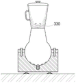
The intelligent mixer of the present invention relates to a mixer for pulverizing or mixing food accommodated therein by a rotating blade, and as shown in fig. 18 to 21d, includes a body 310, an accommodating portion 320, a blade 330, a supporting portion 340, and an inclined forming portion 350.
The main body 310 has a first motor 311 built therein, and the first motor 311 is operated by an internal power source such as a battery or an external power source.
The receiving part 320 is used to receive food therein, and is detachably coupled to an upper portion of the body 310.
The receiving portion 320 includes an upper cup 321 formed in a substantially ∩ shape, and a pad 322 coupled to a lower portion of the upper cup 321 to cover the lower portion of the upper cup 321.
The pad 322 is detachably coupled to the upper surface of the body 310.
As described above, the receiving portion 320 is formed of the upper cup 321 and the pad 322, and the receiving portion 320 can be independently separated from or coupled to the body 310 in a state in which food is inserted into the receiving portion 320 and is sealed.
The blade 330 is rotatably mounted in the receiving portion 320, and more particularly, is mounted on the upper portion of the pad 322.
The blade 330 is rotated by the first motor 311 to crush and/or mix the food accommodated in the accommodating portion 320.
The blade 330 is coupled to the first motor 311 mounted on the body 310, and is rotated by the rotation of the first motor 311.
The support 340 is disposed at a lower portion of the body 310, and supports the body 310 with respect to the ground.
The supporting portion 340 may be formed in various structures, and in this embodiment, the supporting portion 340 includes: a support plate 341 disposed at a lower portion of the body 310; and a support protrusion 342 protruding upward from the support plate 341.
The side of the body 310 is rotatably combined with the supporting protrusion 342.
Therefore, the body 310 is rotatably coupled to the support protrusions 342 to support the body 310 such that the body 310 is rotated in the vertical direction with reference to a horizontal axis.
An adsorption plate 344 made of rubber or the like is attached to a lower surface of the support plate 341 to stably fix the support part 340 to the ground, and it is preferable that the support part 340 is fixed so as not to be shaken when the agitator is operated.
In the support part 340, except for the same structure as the present embodiment, the lower part of the body 310 is combined with the support part 340 in a structure of being bolted to each other, etc., so as to be rotatably supported.
The inclined forming portion 350 allows the main body 310 to be arranged to be inclined with respect to the supporting portion 340.
In a state where the support part 340 is immediately disposed along the vertical direction, the main body 310 and the receiving part 320 are tilted by the tilt forming part 350.
In this embodiment, the inclination forming part 350 includes a driving part for rotating the body 310 so that the body 310 is rotated and inclined in the vertical direction.
The driving unit may rotate the main body 310 by receiving an external force.
In the present embodiment, the driving part is formed by the second motor 352, but the driving part may be formed by a cylinder, a Linear (LM) guide, or the like according to circumstances.
The main body 310 is disposed to be inclined with respect to the supporting portion 340 by the operation of the driving portion, i.e., the second motor 352.
More specifically, in the present embodiment, the inclination forming part 350 includes a driving gear 353 and a driven gear 354 in addition to the second motor 352.
The second motor 352 is mounted on the upper portion of the support plate 341.
The driving gear 353 is attached to the second motor 352.
The driven gear 354 is coupled to a lower portion of the body 310 and engaged with the driving gear 353.
Therefore, when power is applied to the second motor 352, the driven gear 354 is moved by the rotation of the driving gear 353, and the main body 310 is tilted with respect to the supporting portion 340.
In this case, the driven gear 354 may be formed of a circular gear, a rack gear, or the like.
The second motor 352 may maintain the main body 310 in a state of being inclined at a predetermined angle, and may swing the main body 310 in the left-right direction by rotating the driving gear 353 in the forward and reverse directions.
In the present embodiment, the tilt forming part 350 includes a second motor 352, a driving gear 353, and a driven gear 354, and the main body 310 may be tilted and rotated by another gear structure (3 worm gear coupling, spur gear coupling, etc.).
In a state where the support part 340 is hinge-coupled to the side surface of the body 310, the inclined forming part 350 is attached to the side surface hinge portion of the body 310, and the body 310 may be arranged to be inclined with respect to the support part 340.
With the above-described configuration, the first motor 311 rotates the blade 330, and the second motor 352 rotates the main body 310.
Therefore, the food and the like existing in the receiving portion 320 are pulverized at a time by the rotation of the blade 330 of the first motor 311.
Further, since the main body 310 is inclined at least 2 degrees including a vertical line by the second motor 352, food or the like which is not crushed among food or the like pushed to the vicinity of the inner wall of the receiving part 320 by the centrifugal force according to the rotation of the blade 330 is moved toward the center direction where the blade 330 is disposed, and thus the food is crushed again by the blade 330, more effectively crushing the food.
On the other hand, the present invention may further include a measurement unit 360 and a control unit 370.
The measuring unit 360 detects rotation data of the blade 330.
More specifically, the measuring unit 360 detects the rotational speed of the blade 330, the torque of the first motor 311, the current value applied to the first motor 311, and the like.
The control unit 370 controls the driving unit, that is, the second motor 352.
When the rotation state of the blade 330 detected by the measuring unit 360 exceeds a predetermined reference range, the control unit 370 operates the second motor 352 such that the main body 310 is disposed to be inclined with respect to the supporting unit 340.
When the measuring unit 360 detects the rotation speed of the blade 330, if the rotation speed of the blade 330 detected by the measuring unit 360 is higher than a predetermined reference speed, food or the like existing in the accommodating unit 320 is pushed out to the vicinity of the inner wall of the accommodating unit 320 by a centrifugal force based on the rotation of the blade 330, and the control unit 370 determines that the blade 330 rotates faster, and operates the second motor 352 to dispose the main body 310 obliquely with respect to the supporting unit 340.
When the measuring unit 360 detects the torque of the first motor 311 rotating the blade 330, if the torque of the blade 330 detected by the measuring unit 360 is smaller than a predetermined reference torque, food or the like existing in the accommodating unit 320 is pushed to the vicinity of the inner wall of the accommodating unit 320 by a centrifugal force based on the rotation of the blade 330, the control unit 370 determines that the torque of the first motor 311 is small, and operates the second motor 352 to dispose the main body 310 obliquely with respect to the supporting unit 340.
When the measuring unit 360 detects a current value applied to the first motor 311 rotating the blade 330, if the current value detected by the measuring unit 360 is smaller than a predetermined reference current value, food or the like existing in the accommodating unit 320 is pushed to the vicinity of the inner wall of the accommodating unit 320 by a centrifugal force according to the rotation of the blade 330, the control unit 370 determines that the detected current value is small, and operates the second motor 352 to dispose the main body 310 obliquely with respect to the supporting unit 340.
As described above, since the main body 310 is inclined by the second motor 352, the food pushed to the vicinity of the inner wall of the receiving portion 320 is inclined toward the center of the blade 330 by gravity.
Therefore, the above-described blade 330 can more effectively crush food that has not been crushed.
The present invention may further include a timer 365 that operates the second motor 352 at predetermined time intervals without the measurement unit 360 and the control unit 370.
The second motor 352 is periodically operated by the timer 365 such that the main body 310 is tilted at a predetermined angle or shaken in the left and right directions.
As described above, in the present invention, the second motor 352 is operated to maintain the main body 310 in an inclined state with respect to a vertical line, and the main body 310 may be repeatedly swung in the left and right directions with respect to the supporting part 340.
The operation of the present invention formed by the above-described configuration will be described below.
As shown in fig. 21a, food is put into the receiving part 320, and the receiving part 320 is coupled to the body 310.
At this time, the receiving portion 320 can receive food therein and be closed by itself, thereby preventing the food from flowing out of or falling off from the receiving portion 320.
The support part 340 is stably fixed to the floor surface without rattling by the suction plate 344 attached to the lower surface of the support part 340.
In this state, when the first motor 311 is operated, the blade 330 rotates, and as shown in fig. 21b, a part of the food is crushed and pushed to the vicinity of the inner wall of the accommodating part 320 by a centrifugal force.
Therefore, the food has a portion that is not crushed by the blade 330.
In an initial state where food is put into the storage part 320 and pulverized, the food acts as a load to the rotational motion of the blade 330, the rotational speed of the blade 330 is reduced, the torque of the first motor 311 is increased, and the current value applied to the first motor 311 is increased.
Thereafter, as shown in fig. 21b, when the food is pushed to the vicinity of the inner wall of the accommodating portion 320, the load for reducing the rotational motion of the blade 330 is reduced, and therefore, the rotational speed of the blade 330 is higher than the initial state shown in fig. 21a, the torque of the first motor 311 is reduced, and the current value applied to the first motor 311 is reduced.
As shown in fig. 21c, when the measurement unit 360 detects the rotation data of the blade 330, the control unit 370 determines that the rotation state of the blade 330 exceeds a predetermined reference range, and operates the second motor 352 to tilt the main body 310 with respect to the support 340.
Therefore, as the receiving part 320 is inclined, the food pushed to the vicinity of the inner wall of the receiving part 320 is inclined again toward the center of the blade 330 by gravity, and the food not yet pulverized is more effectively pulverized by the blade 330.
At this time, the second motor 352 is operated to rotate the body 310 coupled to the receiving portion 320 about the hinge coupled to the supporting portion 340, thereby being inclined at a plurality of stages.
As shown in fig. 21d, the body 310 is inclined in the direction opposite to the state shown in fig. 21c, and the inclined state in the left-right direction is repeated so that the food existing in the accommodating part 320 moves in the direction of the blade 330, thereby uniformly mixing and pulverizing the food.
On the other hand, in the case where the measuring section 360 is not provided, the main body 310 may be tilted at predetermined time intervals by the timer 365, and in the case where the timer 365 is not provided, the user may operate the second motor 352 or operate the second motor 352 together with the first motor 311 from the beginning to tilt the main body 310 as required.
Eleventh embodiment
Fig. 22 is an exploded perspective view of a pulsator according to an eleventh embodiment of the present invention, fig. 23 is a sectional structure view of the pulsator according to the eleventh embodiment of the present invention, and fig. 24a to 24d are operation process views of the pulsator according to the eleventh embodiment of the present invention.
As shown in fig. 22 to 24d, the eleventh embodiment includes a body 310, a receiving portion 320, a blade 330, a supporting portion 340 and an inclined forming portion 350.
The body 310, the receiving portion 320, and the blade 330 are the same as those of the tenth embodiment, and the detailed description thereof will be omitted, and the support portion 340 and the inclined portion 350 will be mainly described.
The support part 340 is hinge-coupled to a lower portion of the body 310 to support the body 310.
The inclined forming part 350 is installed at a hinge coupling portion between the body 310 and the support part 340 to maintain the body 310 in an inclined state with respect to the support part 340.
That is, the inclination forming part 350 forms the main body 310 at a predetermined angle with respect to the supporting part 340 and maintains the inclined state.
In the present embodiment, the inclined forming portion 350 includes a locking member 355 and a locking adjusting member 356.
The locking member 355 is attached to one of the body 310 and the support 340, and has a plurality of locking grooves 355 a.
The locking adjustment member 356 is attached to the remaining one of the body 310 and the support 340 and inserted into the locking groove 355 a.
In this embodiment, the locking member 355 is attached to the support 340, and the locking adjustment member 356 is attached to the main body 310.
In the inclined forming part 350, when the main body 310 is rotated, the locking adjustment member 356 is inserted into the locking groove 355a to maintain the main body 310 and the receiving part 320 in an inclined state.
The capture adjustment member 356 may be formed of a variety of configurations, including, for example: a ball member 356a inserted into the locking groove 355 a; and a spring 356b elastically supporting the ball 356a toward the locking groove 355 a.
The locking adjustment member 356 may be formed of a plate spring 3 (not shown) having a locking protrusion formed thereon.
At this time, the locking protrusion is formed to be inserted into the locking groove 355 a.
The locking member 355 serving as the locking adjustment member 356 may have various configurations other than the above-described one.
With the above-described structure, when the main body 310 is rotated, the ball member 356a is inserted into the locking groove 355a by the spring 356b, and the main body 310 can be maintained in a state of being inclined at a predetermined angle.
The operation of the present invention having the above-described configuration will be described below.
As shown in fig. 24a, food is put into the receiving part 320, and the receiving part 320 is coupled to the body 310.
Since the blade 330 is rotated by the operation of the first motor 311, as shown in fig. 24b, a part of the food is crushed and pushed to the vicinity of the inner wall of the accommodating part 320 by the centrifugal force according to the rotation of the blade 330.
Therefore, the food has a portion that is not crushed by the blade 330.
Then, as shown in fig. 24c or 24d, when the user tilts the main body 310 in one direction, the main body 310 rotates about a hinge coupling portion with the support portion 340.
At this time, the ball 356a compresses the spring 356b, and is inserted into the new locking groove 355a by the elastic restoring force of the compressed spring 356b, so that the main body 310 is maintained in a state of being inclined at a predetermined angle.
Therefore, the food pushed to the vicinity of the inner wall of the receiving part 320 moves by gravity and is crushed by the blade 330.
Then, according to the kind of food or the degree of pulverization, the main body 310 is further rotated around the hinge coupling portion of the main body 310 and the supporting portion 340, so that the main body pulverizes the food in a stably fixed state at various angles 310.
Otherwise, the other matters are the same as and similar to those of the tenth embodiment, and detailed description thereof will be omitted.
Twelfth embodiment
Fig. 25 is a perspective view of a mixer according to a twelfth embodiment of the present invention, fig. 26 is a sectional structural view of the mixer according to the twelfth embodiment of the present invention, and fig. 27a to 27d are operation diagrams of the mixer according to the twelfth embodiment of the present invention.
As shown in fig. 25 to 27d, the twelfth embodiment includes a body 310, a receiving portion 320, a blade 330, a supporting portion 340, an elastic member 375, and an inclined forming portion 350.
The body 310, the receiving portion 320, and the blade 330 are the same as those of the eleventh embodiment, and detailed description thereof will be omitted, and the support portion 340, the elastic member 375, and the inclined portion 350 will be mainly described.
The support part 340 includes: a support plate 341 disposed at a lower portion of the body 310; and a support protrusion 342 protruding upward from the support plate 341.
The side of the body 310 is rotatably hinge-coupled with the supporting protrusion 342.
The elastic member 375 is disposed between the lower portion of the body 310 and the supporting plate 341, and elastically supports the body 310 upward.
The body 310 is stably supported together with the support protrusion 342 by the elastic member 375.
The inclined forming part 350 is attached to the vicinity of a side portion of the main body 310, which is a hinge coupling portion between the main body 310 and the supporting part 340, and maintains the main body 310 in an inclined state with respect to the supporting part 340.
That is, the inclination forming part 350 maintains the main body 310 in an inclined state to form a predetermined angle with respect to the supporting part 340.
At this time, the stopped state maintaining force of the body 310 formed by the inclined forming portion 350 is greater than the elastic force of the elastic member 375.
The specific configuration and structure of the inclined formation portion 350 described above are the same as and similar to those of the tenth embodiment.
The operation of the present invention formed by the above-described configuration will be described below.
As shown in fig. 27a, food is put into the receiving part 320, and the receiving part 320 is coupled to the body 310.
Since the blade 330 is rotated by the operation of the first motor 311, as shown in fig. 27b, a part of the food is crushed and pushed out to the vicinity of the inner wall of the accommodating part 320 by the centrifugal force generated by the rotation of the blade 330.
Therefore, the food has a portion that is not crushed by the blade 330.
Then, as shown in fig. 27c or 28, when the user tilts the main body 310 in one direction, the main body 310 rotates about a hinge coupling portion with the support portion 340.
At this time, the lower portion of the body 310 is supported by the elastic member 375, and thus can be stably supported in the vertical direction without falling.
Therefore, the food pushed to the vicinity of the inner wall of the receiving part 320 moves by gravity and is crushed by the blade 330.
Then, the main body 310 is further rotated around the hinge coupling portion of the main body 310 and the supporting portion 340 according to the kind of food or the degree of pulverization, so that the main body 310 pulverizes the food in a stable fixed state at various angles.
Further, since the force for maintaining the stopped state of the body 310 by the inclined forming portion 350 is greater than the elastic force of the elastic member 375, the body 310 is prevented from being rotated freely by the elastic force of the elastic member 375.
Otherwise, the other matters are the same as and similar to those of the eleventh embodiment, and detailed description thereof is omitted.
Thirteenth embodiment
Fig. 28 is a sectional structural view of a pulsator according to a thirteenth embodiment of the present invention, and fig. 29a to 29d are views illustrating an operation of the pulsator according to the thirteenth embodiment of the present invention.
As shown in fig. 28 to 29d, the thirteenth embodiment includes a body 310, a receiving portion 320, a blade 330, a supporting portion 340 and an inclined forming portion 350.
The receiving portion 320 and the blade 330 are the same as those of the eleventh embodiment, and detailed description thereof will be omitted, and the main body 310, the supporting portion 340, and the inclined portion 350 will be mainly described.
A dome-shaped insertion protrusion 315 is formed to protrude from a lower portion of the body 310, and an insertion groove 345 into which the insertion protrusion 315 is inserted and rotated is formed at an upper portion of the support 340.
Therefore, when the body 310 is rotated, the insertion protrusion 315 is supported by being rotated inside the insertion groove 345.
At this time, the insertion protrusion 315 is inserted into and coupled to the insertion groove 345 so as not to be separated from each other.
The inclination forming part 350 maintains the body 310 rotated by the insertion protrusion 315 and the insertion groove 345 in a state of being rotated at a predetermined angle.
In the present embodiment, the inclined formation portion 350 includes a fixing groove 357 and a fixing protrusion 358.
The fixing groove 357 is formed in plural and formed in the insertion protrusion 315.
The fixing projection 358 protrudes from the supporting part 340 and is inserted into the fixing groove 357.
At this time, the fixing projection 358 may be inserted into the fixing groove 357 by its own elastic force, or may be elastically supported by a spring or the like.
By inserting the fixing projection 358 into the fixing groove 357, the body 310 is rotated to maintain a multi-stage inclined state by rotating the supporting part 340, as shown in fig. 29a to 29 d.
Unlike the present embodiment, the fixing groove 357 may be formed at the supporting portion 340, and the fixing protrusion 358 may be formed at the insertion protrusion 315.
Also, the above-described inclination forming part 350 may be formed of various structures in addition to the structure of the present embodiment.
For example, the inclined forming portion 350 may be formed by an outer circumferential surface of the insertion protrusion 315 and an inner circumferential surface of the insertion groove 345 contacting each other.
At this time, the outer circumferential surface of the insertion protrusion 315 and the inner circumferential surface of the insertion groove 345 are almost tightly closed, and the body 310 may be maintained in a tilted state by friction generated by contact between the outer circumferential surface of the insertion protrusion 315 and the inner circumferential surface of the insertion groove 345.
Otherwise, the same matters as and similar to the plurality of the above-described embodiments are omitted.
The intelligent agitator and the operation method thereof according to the present invention are not limited to the above-described embodiments, and various modifications can be made within the scope of the technical idea of the present invention.
Industrial applicability
The present invention is applicable to a blender for blending pulverized food.
Claims (19)
1. An intelligent stirrer for crushing or mixing food accommodated in the stirrer by a rotating blade is characterized in that,
the method comprises the following steps:
a body in which a first motor is built;
a receiving part detachably coupled to an upper part of the body and receiving food therein;
a blade mounted inside the accommodating part and rotating by the first motor to crush or mix food;
a support part rotatably coupled to and supporting the body; and
an inclined forming part for making the main body inclined relative to the supporting part,
the main body and the receiving portion are disposed to be inclined with respect to the supporting portion by the inclined forming portion.
2. The intelligent mixer of claim 1,
the inclined forming part comprises a driving part which rotates the body in a mode of inclining the body along the vertical direction,
the main body is disposed to be inclined with respect to the support portion by the operation of the driving portion.
3. The intelligent agitator of claim 2, wherein the drive portion is formed by a second motor.
4. The intelligent mixer of claim 3,
the inclined forming part further includes:
a drive gear attached to the second motor; and
a driven gear combined with the lower part of the body and meshed with the driving gear,
the main body is tilted with respect to the support portion while the driven gear is moved by rotation of the drive gear by the second motor.
5. The intelligent mixer of claim 2,
further comprising:
a measuring section for detecting rotation data of the blade; and
a control part for controlling the operation of the driving part,
when the rotation state of the blade detected by the measuring unit exceeds a preset reference range, the control unit operates the driving unit so that the main body is disposed to be inclined with respect to the support unit.
6. The intelligent mixer of claim 5,
the measuring section detects the rotational speed of the blade,
when the rotational speed of the blade detected by the measuring unit is higher than a preset reference speed, the control unit operates the driving unit so that the main body is disposed to be inclined with respect to the support unit.
7. The intelligent mixer of claim 5,
the measuring unit detects the torque of the first motor for rotating the blade,
when the torque of the blade detected by the measuring unit is smaller than a preset reference torque, the control unit operates the driving unit so that the main body is disposed to be inclined with respect to the support unit.
8. The intelligent mixer of claim 5,
the measuring section detects a current value applied to the first motor, the first motor rotates the blade,
when the current value detected by the measuring unit is smaller than a preset reference current value, the control unit operates the driving unit so that the main body is disposed to be inclined with respect to the supporting unit.
9. The intelligent mixer according to claim 2, further comprising a timer for driving the driving unit at predetermined intervals.
10. The intelligent agitator of claim 2, wherein the body is repeatedly swung in a left-right direction with respect to the support portion by operation of the driving portion.
11. The intelligent agitator of claim 1, wherein the inclination forming part forms the main body to a predetermined angle with respect to the support part and maintains an inclined state.
12. The intelligent mixer of claim 11,
the support part is hinged with the lower part of the body to support the body,
the inclined forming part is mounted on the hinge joint part of the main body and the supporting part to maintain the inclined state of the main body relative to the supporting part.
13. The intelligent mixer of claim 11,
the support portion includes:
a support plate disposed at a lower portion of the body; and
a support protrusion protruding upward from the support plate,
the side of the body is hinged with the supporting protrusion,
an elastic member is disposed between the lower portion of the body and the support plate to elastically support the body upward,
the inclined forming part is mounted on the hinge joint part of the main body and the supporting protrusion to maintain the inclined state of the main body relative to the supporting part,
the stop state maintaining force of the main body formed by the inclined forming part is larger than the elastic force of the elastic component.
14. The intelligent mixer of claim 11,
the inclined forming part includes:
a locking member mounted on one of the body and the support portion and having a plurality of locking grooves formed therein; and
a locking adjustment member mounted on the remaining one of the body and the support portion and inserted into the locking groove,
when the body rotates, the locking adjusting member is inserted into the locking groove to maintain the body and the accommodating portion in an inclined state.
15. The intelligent agitator of claim 14, wherein the latching adjustment member is formed of a plate spring formed with a latching protrusion.
16. The intelligent mixer of claim 14,
the locking adjustment member includes:
a ball member inserted into the locking groove; and
and a spring elastically supporting the ball member along the direction of the locking groove.
17. The intelligent mixer of claim 11,
a dome-shaped insertion protrusion is formed at the lower part of the body,
an insertion groove which is rotated by inserting the insertion protrusion is formed at an upper portion of the support portion,
when the body is rotated, the insertion protrusion is rotated inside the insertion groove, and the inclined forming portion maintains the rotated state.
18. The intelligent mixer of claim 17,
the inclined forming part is formed by the outer circumference of the insertion protrusion and the inner circumference of the insertion groove which are contacted with each other,
the body maintains the inclined state by friction generated by contact between the outer circumferential surface of the insertion protrusion and the inner circumferential surface of the insertion groove.
19. The intelligent mixer of claim 17,
the inclined forming part includes:
a fixing groove formed on the insertion protrusion; and
a fixing protrusion protruding from the support part and inserted into the fixing groove,
the fixing protrusion is inserted into the fixing groove to maintain the body in its state.
Applications Claiming Priority (7)
| Application Number | Priority Date | Filing Date | Title |
|---|---|---|---|
| KR1020140181958A KR101668853B1 (en) | 2014-12-17 | 2014-12-17 | Mixing apparatus |
| KR10-2014-0181958 | 2014-12-17 | ||
| KR1020150019440A KR101681896B1 (en) | 2015-02-09 | 2015-02-09 | Mixing apparatus |
| KR10-2015-0019440 | 2015-02-09 | ||
| KR1020150107859A KR101681467B1 (en) | 2015-07-30 | 2015-07-30 | Smart mixer |
| KR10-2015-0107859 | 2015-07-30 | ||
| CN201580066637.3A CN107278131B (en) | 2014-12-17 | 2015-12-16 | Intelligent stirrer |
Related Parent Applications (1)
| Application Number | Title | Priority Date | Filing Date |
|---|---|---|---|
| CN201580066637.3A Division CN107278131B (en) | 2014-12-17 | 2015-12-16 | Intelligent stirrer |
Publications (1)
| Publication Number | Publication Date |
|---|---|
| CN111053473A true CN111053473A (en) | 2020-04-24 |
Family
ID=56127798
Family Applications (3)
| Application Number | Title | Priority Date | Filing Date |
|---|---|---|---|
| CN201580066637.3A Expired - Fee Related CN107278131B (en) | 2014-12-17 | 2015-12-16 | Intelligent stirrer |
| CN201911256643.1A Pending CN111096691A (en) | 2014-12-17 | 2015-12-16 | Intelligent stirrer |
| CN201911257127.0A Pending CN111053473A (en) | 2014-12-17 | 2015-12-16 | Intelligent stirrer |
Family Applications Before (2)
| Application Number | Title | Priority Date | Filing Date |
|---|---|---|---|
| CN201580066637.3A Expired - Fee Related CN107278131B (en) | 2014-12-17 | 2015-12-16 | Intelligent stirrer |
| CN201911256643.1A Pending CN111096691A (en) | 2014-12-17 | 2015-12-16 | Intelligent stirrer |
Country Status (3)
| Country | Link |
|---|---|
| US (1) | US10842321B2 (en) |
| CN (3) | CN107278131B (en) |
| WO (1) | WO2016099145A2 (en) |
Cited By (1)
| Publication number | Priority date | Publication date | Assignee | Title |
|---|---|---|---|---|
| CN112386094A (en) * | 2020-12-01 | 2021-02-23 | 珠海优特智厨科技有限公司 | Control method of cooking appliance and cooking system |
Families Citing this family (6)
| Publication number | Priority date | Publication date | Assignee | Title |
|---|---|---|---|---|
| KR101760710B1 (en) * | 2017-02-13 | 2017-07-24 | (주)상원 | Vertical moving and swing type blender |
| KR102092010B1 (en) | 2018-06-19 | 2020-03-24 | (주)금오전자 | Stylus pen holder |
| CN110447674A (en) * | 2019-08-06 | 2019-11-15 | 江门市新会恒隆家居创新用品有限公司 | A kind of automatic dough mixing machine |
| CN111153027B (en) * | 2020-02-11 | 2021-09-17 | 泉州台商投资区明云机械有限公司 | Auxiliary heating box for microwave oven |
| CN115734730B (en) | 2020-04-30 | 2025-10-28 | 品谱公司 | Anti-cavitation agitator with vertical tank actuation |
| CN113713675A (en) * | 2021-09-10 | 2021-11-30 | 青岛彩意科技集团有限公司 | Energy-concerving and environment-protective material processing mixing apparatus that uses |
Citations (8)
| Publication number | Priority date | Publication date | Assignee | Title |
|---|---|---|---|---|
| GB122749A (en) * | 1918-04-02 | 1919-02-06 | Edmund Herbert Hick | Improvements in Churns. |
| JPS59184924U (en) * | 1983-05-27 | 1984-12-08 | 株式会社 柳屋鉄工所 | Mixing stirrer |
| CN2128859Y (en) * | 1992-09-03 | 1993-03-31 | 颜清河 | Automatic frying mixer device |
| JP2002066290A (en) * | 2000-08-25 | 2002-03-05 | Aichi Electric Co Ltd | Mixing device |
| JP2002253191A (en) * | 2001-03-05 | 2002-09-10 | Audio Technica Corp | Food stirrer |
| CN101642350A (en) * | 2008-08-04 | 2010-02-10 | 李文庆 | Tilting type automatic stirring and baking bread maker |
| US7717613B1 (en) * | 2008-12-10 | 2010-05-18 | Edward Epps | Portable blender with swiveling base |
| CN102144899A (en) * | 2011-02-01 | 2011-08-10 | 广州市拓璞电器发展有限公司 | Milk foam maker |
Family Cites Families (6)
| Publication number | Priority date | Publication date | Assignee | Title |
|---|---|---|---|---|
| KR0126936Y1 (en) | 1996-02-03 | 1998-09-15 | 김광호 | A mixer |
| US7217029B2 (en) * | 2004-02-26 | 2007-05-15 | Hognon Sa | Mixer with lump breaker having multiple axes of rotation |
| KR101034965B1 (en) * | 2009-03-26 | 2011-05-17 | 김산동 | mixer |
| KR101065898B1 (en) | 2010-06-08 | 2011-09-19 | 유순식 | Dehydration mixer |
| KR20120000011U (en) * | 2010-06-25 | 2012-01-02 | 박동영 | Baby Pot Cup |
| KR20120000011A (en) * | 2010-06-26 | 2012-01-03 | 엘지전자 주식회사 | Network system and energy consumption department |
-
2015
- 2015-12-16 CN CN201580066637.3A patent/CN107278131B/en not_active Expired - Fee Related
- 2015-12-16 US US15/752,742 patent/US10842321B2/en not_active Expired - Fee Related
- 2015-12-16 CN CN201911256643.1A patent/CN111096691A/en active Pending
- 2015-12-16 WO PCT/KR2015/013782 patent/WO2016099145A2/en not_active Ceased
- 2015-12-16 CN CN201911257127.0A patent/CN111053473A/en active Pending
Patent Citations (8)
| Publication number | Priority date | Publication date | Assignee | Title |
|---|---|---|---|---|
| GB122749A (en) * | 1918-04-02 | 1919-02-06 | Edmund Herbert Hick | Improvements in Churns. |
| JPS59184924U (en) * | 1983-05-27 | 1984-12-08 | 株式会社 柳屋鉄工所 | Mixing stirrer |
| CN2128859Y (en) * | 1992-09-03 | 1993-03-31 | 颜清河 | Automatic frying mixer device |
| JP2002066290A (en) * | 2000-08-25 | 2002-03-05 | Aichi Electric Co Ltd | Mixing device |
| JP2002253191A (en) * | 2001-03-05 | 2002-09-10 | Audio Technica Corp | Food stirrer |
| CN101642350A (en) * | 2008-08-04 | 2010-02-10 | 李文庆 | Tilting type automatic stirring and baking bread maker |
| US7717613B1 (en) * | 2008-12-10 | 2010-05-18 | Edward Epps | Portable blender with swiveling base |
| CN102144899A (en) * | 2011-02-01 | 2011-08-10 | 广州市拓璞电器发展有限公司 | Milk foam maker |
Cited By (2)
| Publication number | Priority date | Publication date | Assignee | Title |
|---|---|---|---|---|
| CN112386094A (en) * | 2020-12-01 | 2021-02-23 | 珠海优特智厨科技有限公司 | Control method of cooking appliance and cooking system |
| CN112386094B (en) * | 2020-12-01 | 2022-06-28 | 珠海优特智厨科技有限公司 | Control method of cooking appliance and cooking system |
Also Published As
| Publication number | Publication date |
|---|---|
| WO2016099145A3 (en) | 2016-08-11 |
| WO2016099145A2 (en) | 2016-06-23 |
| CN107278131A (en) | 2017-10-20 |
| CN107278131B (en) | 2020-03-17 |
| US20180255974A1 (en) | 2018-09-13 |
| CN111096691A (en) | 2020-05-05 |
| US10842321B2 (en) | 2020-11-24 |
Similar Documents
| Publication | Publication Date | Title |
|---|---|---|
| CN111096691A (en) | Intelligent stirrer | |
| JP6605626B2 (en) | Vertical movement and swing type mixer | |
| KR101681896B1 (en) | Mixing apparatus | |
| US20240090706A1 (en) | Portable blade grinder | |
| KR101968336B1 (en) | Rotary mixer | |
| KR101668853B1 (en) | Mixing apparatus | |
| CN218683927U (en) | Stirring machine | |
| KR101681467B1 (en) | Smart mixer | |
| CN106488798B (en) | Stirring devices and laboratory equipment incorporating such stirring devices | |
| CN211672160U (en) | Mixer with safety switch | |
| JP4072480B2 (en) | Hand mixer stand | |
| CN101930880B (en) | Remote moulded case circuit breaker motor-driven operating mechanism with energy pre-storage function | |
| JP4439442B2 (en) | Crushing instrument and crushing apparatus provided with the same | |
| CN209733756U (en) | Cup of kneading dough and cooking machine | |
| KR200188522Y1 (en) | Device for kneading powder | |
| CN217615241U (en) | Breaker feed mechanism is used in light calcined powder processing | |
| CN220929717U (en) | Fan with object placing function | |
| CN218922360U (en) | Food processor | |
| CN215383411U (en) | Coffee grinder | |
| CN115138272B (en) | Easy stirring device | |
| CN214259094U (en) | Cover body assembly and food processing device | |
| JP2020168228A (en) | mixer | |
| KR20050026245A (en) | Touch screen corporation device for internet refrigerator | |
| JP2004155367A (en) | Motor-driven mirror storing device | |
| CN209732412U (en) | cup of kneading dough and cooking machine |
Legal Events
| Date | Code | Title | Description |
|---|---|---|---|
| PB01 | Publication | ||
| PB01 | Publication | ||
| SE01 | Entry into force of request for substantive examination | ||
| SE01 | Entry into force of request for substantive examination | ||
| WD01 | Invention patent application deemed withdrawn after publication |
Application publication date: 20200424 |
|
| WD01 | Invention patent application deemed withdrawn after publication |