Method for recovering NMP solvent in process of preparing acetylene by partial oxidation of natural gas
Technical Field
The invention belongs to the technical field of separation realized by evaporation of a thin-layer liquid in contact with a heated surface, and particularly relates to a method for recovering an NMP solvent in a process for preparing acetylene by partial oxidation of natural gas.
Background
Acetylene is a very important organic chemical raw material, and is widely used in the fields of metal processing, welding, cutting and the like, and the preparation of chemical products such as ethylene, vinyl chloride, trichloroethylene, vinyl acetate, acrylonitrile, polyacrylonitrile, 1, 4-butanediol and the like ("the new development of acetylene in organic synthetic chemistry", step wins, China chemical trade, No. 7, No. 22, No. 103, No. 12 and No. 31 of published date 2015; "the research progress of acetylene preparation by low-carbon alkane pyrolysis through thermal plasma", Subaogen and the like, chemical reaction engineering and processes, No. 29, No. 3, No. 29, No. 230 and No. 236 of published date 2013, No. 06 and No. 30 of published date 2013). The preparation method of acetylene mainly comprises a non-catalytic partial oxidation method, an electric arc method, a plasma method and the like, wherein the electric arc method is eliminated due to high energy consumption, the plasma method is still in a test stage (the current state of research of natural gas acetylene, thinking, angry, vinylon communication, No. 33, No. 2, No. 15-20, No. 2013, No. 12, No. 31 in 2013), the power consumption is high, the requirements on equipment are harsh, the method is difficult to popularize and apply so far, and the non-catalytic partial oxidation method is a main method for producing acetylene.
In the prior art, the main structure and the main production process of a production device adopted in the process of preparing acetylene by non-catalytic partial oxidation of natural gas are as follows: the natural gas pipeline and the oxygen pipeline are respectively connected with a gas heater, natural gas and oxygen are respectively preheated to 600-650 ℃, the natural gas is firstly introduced into the acetylene reaction furnace, when the temperature of the natural gas reaches a set value, an auxiliary oxygen regulating valve of the reaction furnace is opened, and an ignition gun is operated to ignite; introducing oxygen for oxygen feeding after ignition is successful, wherein reaction gas consisting of natural gas and oxygen generates partial oxidation reaction in a reaction chamber of an acetylene furnace, cooling after reaction for a few milliseconds to finish the reaction, and hydrocarbon is partially oxidized and cracked into a cracked gas mixture containing acetylene, carbon monoxide, carbon dioxide, hydrogen, carbon black and other components; and (3) after the cracked gas mixture from the acetylene reaction furnace passes through the lower section of the cooling tower, the electric dust remover and the upper section of the cooling tower, further cooling and washing carbon black in the cracked gas mixture, and then entering a concentration system through a compressor to obtain acetylene and synthesis gas products. The water containing carbon black discharged from the bottoms of the acetylene furnace, the cooling tower and the electric dust remover enters a collecting pipe, a small amount of gas is removed through flash evaporation by a first-stage sieve plate degassing tank, the water enters an open carbon black water tank, carbon black and water are separated, the obtained clean water is partially returned to the acetylene furnace to be used as quenching water, and one part of the clean water is sent to a cooling tower to be cooled and then sent to the cooling tower, the electric dust remover and a concentration device to be used as spray cooling water (as shown in figure 1).
In the process of preparing acetylene by partial oxidation of natural gas, N-methyl pyrrolidone (NMP) solvent is widely used in the concentration process of cracking gas. Under the condition that the absolute pressure is 0.8-1.0MPa, the cracking gas is in countercurrent contact with NMP sprayed in a segmented mode, and substances such as high alkyne and acetylene which are easily soluble components are absorbed by the NMP. The carrier gas NMP constantly presses the tower and the vacuum tower, and the acetylene component and the higher alkyne component are respectively resolved. During the absorption and analysis of NMP, some of the easily crystallized and easily polymerized components such as benzene, naphthalene and higher alkyne are accumulated in NMP, which affects the absorption capacity of the circulating solvent on one hand, and is easily crystallized and polymerized to form scale on the other hand, thereby blocking pipelines and fillers. In the prior art, part of circulating solvent is taken out and is primarily concentrated by a continuous flash tank, and the bottom NMP solvent is separated by a suspension separator to obtain the concentrated NMP solvent containing the polymer. And (3) the concentrated NMP solvent enters a solvent storage tank, and then is added into a dry distillation tank in batches from the storage tank, so that the clean recovered NMP solvent is obtained after dry distillation. The heavy component dry distillation slag is manually drawn out of the dry distillation tank and transferred to a storage tank. The dry distillation residue contains a small amount of NMP solvent, and the NMP solvent in the dry distillation residue needs to be recovered, otherwise, the loss of the NMP solvent is large.
The existing batch dry distillation system (as shown in figure 2) has low thermal efficiency and long distillation time. As the tank body of the dry distillation tank is heated by the coil, the thermal efficiency of the dry distillation equipment is about 55 percent, the thermal efficiency is relatively low, the distillation time reaches 22 hours per tank, and the running period is long. The heating temperature of the tank bottom and the tank wall can not be accurately controlled, the local heating is uneven, the dry distillation slag is easy to coke and form blocks, and manual slag removal is needed. The manual slag removal has high labor intensity, a large amount of malodorous VOCs gas is discharged, the environment is polluted, and serious occupational health hazards are easily caused. In addition, the dry distillation residue contains about 29% (mass content) of the NMP solvent, and the NMP solvent in the dry distillation residue needs to be recovered, otherwise, a large amount of NMP solvent is lost. Chinese patent publication No. CN1044474780A discloses a method for continuously recovering NMP solvent from a polyphenylene sulfide production apparatus, which comprises the steps of preheating raw materials, feeding the preheated raw materials into a rectifying tower C-101, extracting waste gas from the top of the tower, forcibly circulating concentrated bottom liquid at the bottom of the tower by a centrifugal pump, dehydrating part of solid products by a centrifugal machine, discharging the dehydrated part of the solid products out of a battery compartment, feeding supernatant mother liquor into the top of the rectifying tower C-102 to separate p-dichlorobenzene, feeding the bottom liquid into the rectifying tower C-103, further cooling and extracting the NMP solvent evaporated from the top of the tower after heat exchange with feed liquid, and extracting a chloride solution of the NMP solvent from the bottom of the tower by a forced circulation pump. The method has the advantages of more refined separation of components in the raw materials, higher separation purity of the product and better operability. However, in the case of an NMP material containing a large amount of heat-sensitive components and easily crystallized components, only a part of the NMP solvent can be separated, and the NMP amount gradually decreases and the solubility of the relatively less volatile matter relatively continuously increases with the amount of the NMP solvent below the feed inlet of the rectifying tower, so that the easily crystallized matter is more easily precipitated. As the concentration of the high polymer increases and the temperature of the bottom increases, the high polymer is easier to polymerize, and part of the polymer can adhere to the inner wall of the tower and the surface of the packing, so that the polymer blocks the packing and pipelines, which is proved in the practice of acetylene concentration production operation for many years; while the other part of the crystals and the polymer are discharged as a suspension liquid through the bottom of the tower, and because of the large amount of NMP solvent contained therein, the NMP recovery rate is obviously low, and the subsequent disposal cost is larger. The high-grade alkyne is the main reason for causing the pipeline blockage of the acetylene concentration system of the acetylene preparation device from natural gas, the high-grade alkyne gas is mainly rich in methylacetylene, vinyl acetylene, butadiene, diacetylene and other components with the trace of more than C4, and due to the existence of unsaturated bonds of each alkyne component, under certain temperature and pressure and in the presence of trace oxygen, peroxide, etc. in the system, free radical polymerization is easy to occur, the generated free radicals generate macromolecular polymers through the processes of chain initiation, chain propagation and chain termination, and a large amount of polymers are easy to deposit and pollute in the high-grade alkyne pipeline and block the equipment pipeline, so that the safe and stable long-period operation of the concentration system is influenced (shallow analysis of blockage reasons of the high-grade alkyne pipeline of the acetylene concentration device, whole soldiers thanks, natural gas chemical industry, volume 36 in 2011, pages 34 to 37, and published day 2011, 12 months and 31 days).
Aiming at the NMP solvent containing heat-sensitive components, how to realize automatic continuous production, how to improve the thermal efficiency in the dry distillation process, how to prevent the residue from being coked in large blocks and realize automatic slag discharge in the treatment process have important significance for the energy consumption, automatic upgrade and disposal of industrial solid waste of a solvent recovery system of a natural gas acetylene concentration device.
Disclosure of Invention
In view of the above, the present invention aims to provide a method for recovering an NMP solvent, which can recover an NMP solvent containing easily crystallized and thermosensitive components, improve the recovery rate, avoid the problem of blockage caused by crystallization and coking, and effectively solve the problems of heavy physical labor caused by manual slag removal and excessive discharge of VOCs and occupational health hazards caused by the heavy physical labor.
In order to achieve the purpose, the technical scheme of the invention is as follows:
a method for recovering NMP solvent comprising the steps of: heating NMP solvent to 80-99 deg.c in preheater, and evaporating in film evaporator for separation.
The method can realize the recovery of the NMP solvent containing the easily crystallized and thermosensitive components, and improves the recovery rate.
The method can avoid the blockage problem caused by crystallization and coking, realize automatic slag discharge and improve the automation level of the dry distillation device.
The method does not need manual slag removal, and does not cause environmental pollution and occupational health hazards.
In order to further improve the recovery rate of the NMP solvent, the preheater is a tubular preheater, and the inner wall of the preheater is polished.
In order to further improve the recovery rate of the NMP solvent, the heating medium is steam or heat conducting oil.
In order to further improve the recovery rate of the NMP solvent, a flow control valve 10 is provided on the liquid phase inlet line of the preheater 1.
In order to further improve the recovery rate of the NMP solvent, the thin film evaporator is a wiped film evaporator.
In order to further improve the recovery rate of the NMP solvent, the scraping blades of the thin film evaporator are movable scraping blades.
In order to further improve the recovery rate of the NMP solvent, the temperature of the thin film evaporator is 120-170 ℃, and the absolute pressure is 1-5 KPa.
In order to further improve the recovery rate of the NMP solvent, the method also comprises the following steps: the gaseous phase NMP from the thin film evaporator was condensed to a liquid phase by a condenser.
In order to further increase the recovery rate of the NMP solvent, the condenser 2 is a vertical shell and tube condenser.
In order to further improve the recovery rate of the NMP solvent, the bottom of the condenser 2 is provided with a liquid outlet which is connected with the solvent recovery tank 6 through a downcomer through which the NMP solvent condensed into a liquid phase falls into the solvent recovery tank 6.
In order to further improve the rate of recovery of the NMP solvent, the solvent recovery tank 6 is provided with a vertically arranged partition board which divides the inner cavity of the tank body into a storage area and a down-flow area, and a gap is reserved between the top of the partition board and the top of the tank body.
In order to further improve the recovery rate of the NMP solvent, one end of the downcomer is connected with a liquid outlet of the condenser 2, the other end of the downcomer is immersed below the liquid level of a liquid descending area of the solvent recovery tank 6, and the vertical distance between the two ends of the downcomer is more than 10 m.
In order to further improve the recovery rate of the NMP solvent, the bottom of the thin film evaporator 3 is provided with a slag discharge port which is communicated with a dry distillation slag collecting tank 4 through a slag discharge pipe, the dry distillation slag collecting tank 4 is arranged below the thin film evaporator 3, the bottom of the dry distillation slag collecting tank 4 is communicated with a dry distillation slag storage tank 5 through a slag discharge pipe, and the dry distillation slag storage tank 5 is arranged below the dry distillation slag collecting tank.
In order to further improve the recovery rate of the NMP solvent, the condenser 2 and the dry distillation residue collection tank 4 are respectively connected with a vacuum pump 7 through pipelines.
In order to further improve the recovery rate of the NMP solvent, a vacuum control valve 8 is arranged on a pipeline connecting the vacuum pump 7 and the dry distillation residue collection tank 4.
In order to further increase the recovery rate of the NMP solvent, the bottom of the dry distillation residue collection tank 4 is provided with a nitrogen flow rate adjustment valve 13.
In order to further improve the recovery rate of the NMP solvent, the slag discharge pipe is provided with a slag discharge valve 11, and the slag discharge pipe is provided with a slag discharge valve 12.
NMP solvent gets into preheater 1 from preheater 1's inlet, and this inlet is provided with the control valve, and preheater 1 adopts conduction oil or steam heating, and this preheater 1 is shell and tube preheater, and preheater 1's inner wall is through polishing treatment. The NMP solvent enters a thin film evaporator 3 after being heated by a preheater 1, the thin film evaporator 3 is a wiped film evaporator, and a wiper blade of the wiped film evaporator 3 is a movable wiper blade. In the thin film evaporator 3, the heated NMP solvent realizes the separation of the gas phase NMP solvent and the solid phase dry distillation slag.
The vapor phase NMP solvent enters a condenser 2 through a pipeline arranged at the top of the thin film evaporator 3, the condenser 2 is a vertical shell and tube condenser, and the bottom of the condenser 2 is provided with a liquid outlet which is connected with a solvent recovery tank 6 through a downcomer.
The liquid phase NMP solvent after the condensation falls into the down-flow district of solvent recovery jar 6 through the downcomer by gravity (solvent recovery jar 6 is provided with the baffle of vertical setting, separates jar internal chamber for storage area and down-flow district with the baffle, leaves the clearance between baffle top and the jar body top).
One end of the downcomer is connected with a liquid outlet of the condenser 2, the other end of the downcomer is immersed below the liquid level of a liquid descending area of the solvent recovery tank 6, and the vertical distance between the two ends of the downcomer is more than 10 m.
The bottom of the thin film evaporator 3 is provided with a slag discharge hole which is communicated with the dry distillation slag collecting tank 4 through a slag discharge pipe, and the dry distillation slag collecting tank 4 is arranged below the thin film evaporator 3. The bottom of the dry distillation residue collecting tank 4 is communicated with the dry distillation residue storage tank 5 through a residue discharge pipe, and the dry distillation residue storage tank 5 is arranged below the dry distillation residue collecting tank 4. The slag discharging pipe is provided with a slag discharging valve 11, and the slag discharging pipe is provided with a slag discharging valve 12.
The vacuum pump 7 is respectively connected with the vertical tube gas condenser 2 and the dry distillation residue collecting tank 4 through pipelines, a vacuum control valve 8 is arranged on the pipeline connecting the vacuum pump 7 and the dry distillation residue collecting tank 4, and a pressure regulating valve 9 is arranged on the pipeline connecting the vacuum pump 7 and the vertical gas condenser 2.
An NMP flow regulating valve 10 is arranged on a liquid inlet pipeline of the preheater 1, electromagnetic valves which are matched with each other are arranged at the bottoms of the thin film evaporator 3 and the dry distillation residue collecting tank 4, and a nitrogen flow regulating valve 13 is arranged at the bottom of the dry distillation residue collecting tank 4.
The nitrogen flow regulating valve 13 is connected with a nitrogen pipe network through a pipeline. During slag discharge, a slag discharge valve 11 on the slag discharge pipe is closed, a vacuum control valve 8 is closed, a nitrogen flow regulating valve 13 is opened, the dry distillation slag collecting tank recovers positive pressure, a slag discharge valve 12 on the slag discharge pipe is opened, and dry distillation slag is discharged into a dry distillation slag storage tank 5 due to gravity. And after the dry distillation slag is discharged, the slag discharging valve 11 on the slag discharging pipe is closed, the nitrogen flow regulating valve 13 is closed, the vacuum control valve 8 is opened, when the pressure reaches the pressure of the thin film evaporator 3, the vacuum control valve 8 is closed, the slag discharging valve 11 on the slag discharging pipe is closed, and the primary slag discharging process is completed. Through the arrangement, the automatic slag discharging function under continuous operation is realized.
The invention has the beneficial effects that:
the method can realize the recovery of the NMP solvent containing the easily crystallized and thermosensitive components, and improves the recovery rate.
The method can avoid the blockage problem caused by crystallization and coking.
The method of the invention does not need manual slag removal, and improves the automation level of the NMP recovery device.
The method can effectively control the excessive discharge of VOCs in the production field, and cannot cause environmental pollution and occupational health hazards.
Drawings
FIG. 1 is a flow diagram of an acetylene concentration system;
FIG. 2 is a schematic view of a batch retort system;
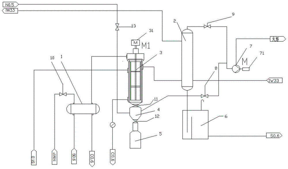
fig. 3 is a thin film evaporator system of example 1, in which 1 is a preheater, 2 is a condenser, 3 is a thin film evaporator, 31(M1) is a thin film evaporator motor, 4 is a dry distillation residue collection tank, 5 is a dry distillation residue storage tank, 6 is a solvent recovery tank, 7 is a vacuum pump, 71(M) is a vacuum pump motor, 8 is a vacuum control valve, 9 is a pressure regulating valve, 10 is an NMP flow regulating valve, 11 is a slag discharge valve, 12 is a slag discharge valve, 13 is a nitrogen flow regulating valve, No.5 is nitrogen gas at a pressure of 0.5MPa, Iw33 is circulating cooling water, S1.0 is heat transfer oil or steam at a pressure of 1MPa, NMP is NMP stock solution, S0.6 is heat transfer oil or steam at a pressure of 0.6MPa, and C0.6 is condensate.
Detailed Description
The examples are provided for the purpose of better illustrating the present invention, and the present invention is not limited to the examples. Therefore, those skilled in the art should make insubstantial modifications and adaptations to the embodiments of the present invention in light of the above teachings and remain within the scope of the invention.
Example 1
Taking an NMP stock solution (from a concentration process in the process of preparing acetylene by partial oxidation of natural gas) for component detection, wherein the result is shown in a table 1;
wherein, the NMP content is detected according to the GB/T614-2006 chemical reagent shading rate determination general method;
the method for detecting the total content of the thermosensitive polymer is a gravimetric method, and specifically comprises the following steps: heating and evaporating the solvent with the mass M under the condition of gas inerting until the measured mass (the mass is N) is obtained, wherein the total content of the thermosensitive polymer is N/M x 100 percent;
the water content is detected according to GB/T6283-2008 determination of the water content in the chemical products;
the content detection of acetylene, methylacetylene, diacetylene, vinylacetylene, divinylacetylene and benzene is carried out by adopting a conventional chromatographic analysis method.
The NMP stock solution is treated by adopting a system shown in the attached figure 3, and the system comprises a preheater 1, a condenser 2, a thin film evaporator 3, a dry distillation residue collecting tank 4, a dry distillation residue storage tank 5, a solvent recovery tank 6 and a vacuum pump 7. The preheater 1 is a shell and tube preheater, the condenser 2 is a vertical shell and tube condenser, the film evaporator 3 is a wiper type film evaporator, and a wiper of the wiper type film evaporator is a movable wiper.
NMP solvent gets into preheater 1 from preheater 1's inlet, and this inlet is provided with the control valve, and preheater 1 adopts conduction oil or steam heating, and preheater 1's inner wall is through polishing treatment. The NMP solvent enters the thin film evaporator 3 after being heated by the preheater 1, and the heated NMP solvent realizes the separation of the gas phase NMP solvent and the solid phase dry distillation slag in the thin film evaporator 3.
The gaseous phase NMP solvent enters the condenser 2 through a pipeline arranged at the top of the thin film evaporator 3, the bottom of the condenser 2 is provided with a liquid outlet, and the liquid outlet is connected with the solvent recovery tank 6 through a downcomer.
The liquid phase NMP solvent after the condensation falls into the down-flow district of solvent recovery jar 6 through the downcomer by gravity (solvent recovery jar 6 is provided with the baffle of vertical setting, and the baffle is separated jar internal chamber for storage area and down-flow district, leaves the clearance between baffle top and the jar body top).
One end of the downcomer is connected with a liquid outlet of the condenser 2, the other end of the downcomer is immersed below the liquid level of a liquid descending area of the solvent recovery tank 6, and the vertical distance between the two ends of the downcomer is more than 10 m.
The bottom of the thin film evaporator 3 is provided with a slag discharge hole which is communicated with a dry distillation slag collecting tank 4 through a slag discharge pipe, and the dry distillation slag collecting tank 4 is arranged below the thin film evaporator 3. The bottom of the dry distillation slag collecting tank 4 is communicated with the dry distillation slag storage tank 5 through a slag discharging pipe, and the dry distillation slag storage tank 5 is arranged below the dry distillation slag collecting tank 4. The slag discharging pipe is provided with a slag discharging valve 11, and the slag discharging pipe is provided with a slag discharging valve 12.
The vacuum pump 7 is respectively connected with the condenser 2 and the dry distillation residue collecting tank 4 through pipelines, a vacuum control valve 8 is arranged on the pipeline connecting the vacuum pump 7 and the dry distillation residue collecting tank 4, and a pressure regulating valve 9 is arranged on the pipeline connecting the vacuum pump 7 and the condenser 2.
The liquid inlet pipeline of the preheater 1 is provided with an NMP flow regulating valve 10, the bottoms of the thin film evaporator 3 and the dry distillation residue collecting tank 4 are provided with mutually matched electromagnetic valves, and the bottom of the dry distillation residue collecting tank 4 is provided with a nitrogen flow regulating valve 13.
The nitrogen flow regulating valve 13 is connected with a nitrogen pipe network through a pipeline. When discharging slag, a slag discharging valve 11 on the slag discharging pipe is closed, a vacuum control valve 8 is closed, a nitrogen flow regulating valve 13 is opened, the dry distillation slag collecting tank recovers positive pressure, a slag discharging valve 12 on the slag discharging pipe is opened, and dry distillation slag is discharged into a dry distillation slag storage tank 5 due to gravity. And after the dry distillation slag is discharged, closing a slag discharging valve 12 on the slag discharging pipe, closing a nitrogen flow regulating valve 13, opening a vacuum control valve 8, closing the vacuum control valve 8 when the pressure reaches the pressure of the thin film evaporator, and opening a slag discharging valve 11 on the slag discharging pipe to finish a slag discharging process. Through the arrangement, the automatic deslagging function of the film evaporator under continuous operation is realized.
The specific process comprises the following steps: adding NMP stock solution into a storage tank before a pump, adjusting a control valve on a preheater 1, and controlling the feeding amount to be 0.3m 3 After preheating to 99 ℃ by the preheater 1, the solvent was introduced into the thin-film evaporator 3 (NMP solvent was added to the falling liquid zone of the solvent recovery tank 6 until the overflow before starting the thin-film evaporator 3). The temperature of the thin film evaporator 3 was adjusted to 170 ℃ and the pressure of the pressure regulating valve 9 was 1.1 to 1.2Pa (absolute pressure). And a slag discharging valve 11 on the slag discharging pipe is opened, a slag discharging valve 12 on the slag discharging pipe is closed, and a nitrogen flow valve 13 is closed. The solvent recovery tank 6 is filled to overflow in the downcomer zone. After 60 minutes, the dry distillation collection tank discharges slag. And (3) starting the dry distillation slag collecting tank 4 to discharge slag, closing a slag discharge valve 11, automatically closing a vacuum control valve 8, filling low-pressure nitrogen into the system through a nitrogen flow regulating valve 13 to recover the positive pressure of the dry distillation slag collecting tank 4, automatically opening a slag discharge valve 12 on a slag discharge pipe, and discharging the bottom dry distillation slag material into a closed dry distillation slag storage tank 5. And after the dry distillation slag is discharged, automatically closing a slag discharging valve 12 on the slag discharging pipe, closing a nitrogen flow regulating valve 13, slowly opening a valve position of a vacuum control valve 8, regulating the vacuum degree of the dry distillation slag collecting tank 4, closing the vacuum control valve 8 when the vacuum degree reaches the system pressure of the thin film evaporator, and automatically opening a slag discharging valve 11 on the slag discharging pipe to finish a slag discharging process.
TABLE 1 NMP stock solution composition test results
| Detecting items
|
The result of the detection
|
| NMP
|
96% (by mass)
|
| Heat-sensitive polymer
|
2.01% (by mass)
|
| Water (W)
|
0.77% (by mass)
|
| Acetylene
|
8mg/L
|
| Methylacetylene
|
20mg/L
|
| Diacetylenes
|
25mg/L
|
| Vinyl acetylene
|
15mg/L
|
| Divinylacetylene
|
27mg/L
|
| Benzene and its derivatives
|
1.9mg/L |
Examples 1, 2 and comparative example 1
The parameters of example 2 were set to the same values as in example 1, except for the parameters shown in Table 2.
Table 2 example 2 and comparative example 1
Comparative example 1
The dry distillation system shown in fig. 2 was used to treat NMP stock solution (same composition as in example 1), specifically:
will be 4m 3 The NMP stock solution is sent into a dry distillation tank, 1MPa heat tracing steam is started, the temperature is raised to 170 ℃, a vacuum system is started, the pressure is controlled to be 1.1-1.2Kpa.A, dry distillation is carried out for 22 hours, and manual slag removal is carried out.
Performance detection
The results of measuring the residual rate of NMP in the dry distillation residues obtained by the methods of examples 1-2 and comparative example 1, the state of the dry distillation residues, and the content of volatile organic compounds (VOCs for short in english) in the ambient air are shown in table 3;
wherein, the NMP content in the dry distillation slag is detected according to the GB/T614-2006 chemical reagent shading rate determination general method;
the detection method of the dry distillation slag state is visual observation;
the detection method of the content of VOCs in the ambient air adopts a portable VOCs detector for field detection.
Table 3 results of performance testing
| Source
|
Residual ratio of NMP/%)
|
Dry residue state
|
Dry residue deslagging status
|
VOCs content/ppm
|
| Example 1
|
12.5
|
In the form of sheet
|
Automatic slag tapping
|
<5
|
| Example 2
|
23.4
|
In the form of sheet
|
Automatic slag tapping
|
<5
|
| Comparative example 1
|
29
|
Coking into cake
|
Manual slag removal
|
1200 |
As is clear from tables 1 and 3, the method of examples 1 to 2 can avoid the problem of clogging due to crystallization and coking, and can recover the NMP solvent containing a readily crystallizable and thermosensitive component, thereby improving the recovery rate.
As is clear from tables 1 and 3, the dry distillation residues treated in examples 1 and 2 were not agglomerated and the slag was discharged automatically and smoothly, as compared with comparative example 1. Therefore, the method disclosed by the invention can avoid the blockage problem caused by crystallization and coking, and effectively improve the automation degree of the dry distillation device.
As is clear from tables 1 and 3, the NMP residual ratio in the dry distilled slag treated in examples 1-2 was remarkably reduced as compared with comparative example 1; and the content of VOCs in the ambient air is significantly reduced. Therefore, the method disclosed by the invention can effectively recover the NMP solvent, effectively control the problem of excessive emission of VOCs in a production field, and solve the occupational health hidden danger in the manual deslagging process.
Furthermore, it should be understood that although the present description refers to embodiments, not every embodiment may contain only a single embodiment, and such description is for clarity only, and those skilled in the art should integrate the description, and the embodiments may be combined as appropriate to form other embodiments understood by those skilled in the art.