CN111706339A - A kind of shield unearthed blowout preventer - Google Patents
A kind of shield unearthed blowout preventer Download PDFInfo
- Publication number
- CN111706339A CN111706339A CN202010470656.5A CN202010470656A CN111706339A CN 111706339 A CN111706339 A CN 111706339A CN 202010470656 A CN202010470656 A CN 202010470656A CN 111706339 A CN111706339 A CN 111706339A
- Authority
- CN
- China
- Prior art keywords
- flange
- pipe
- shield
- fixedly connected
- soil
- Prior art date
- Legal status (The legal status is an assumption and is not a legal conclusion. Google has not performed a legal analysis and makes no representation as to the accuracy of the status listed.)
- Granted
Links
Images


Classifications
-
- E—FIXED CONSTRUCTIONS
- E21—EARTH OR ROCK DRILLING; MINING
- E21D—SHAFTS; TUNNELS; GALLERIES; LARGE UNDERGROUND CHAMBERS
- E21D9/00—Tunnels or galleries, with or without linings; Methods or apparatus for making thereof; Layout of tunnels or galleries
- E21D9/06—Making by using a driving shield, i.e. advanced by pushing means bearing against the already placed lining
-
- E—FIXED CONSTRUCTIONS
- E21—EARTH OR ROCK DRILLING; MINING
- E21D—SHAFTS; TUNNELS; GALLERIES; LARGE UNDERGROUND CHAMBERS
- E21D9/00—Tunnels or galleries, with or without linings; Methods or apparatus for making thereof; Layout of tunnels or galleries
- E21D9/06—Making by using a driving shield, i.e. advanced by pushing means bearing against the already placed lining
- E21D9/0642—Making by using a driving shield, i.e. advanced by pushing means bearing against the already placed lining the shield having means for additional processing at the front end
- E21D9/0678—Adding additives, e.g. chemical compositions, to the slurry or the cuttings
- E21D9/0685—Foaming agents
-
- E—FIXED CONSTRUCTIONS
- E21—EARTH OR ROCK DRILLING; MINING
- E21D—SHAFTS; TUNNELS; GALLERIES; LARGE UNDERGROUND CHAMBERS
- E21D9/00—Tunnels or galleries, with or without linings; Methods or apparatus for making thereof; Layout of tunnels or galleries
- E21D9/12—Devices for removing or hauling away excavated material or spoil; Working or loading platforms
-
- E—FIXED CONSTRUCTIONS
- E21—EARTH OR ROCK DRILLING; MINING
- E21D—SHAFTS; TUNNELS; GALLERIES; LARGE UNDERGROUND CHAMBERS
- E21D9/00—Tunnels or galleries, with or without linings; Methods or apparatus for making thereof; Layout of tunnels or galleries
- E21D9/12—Devices for removing or hauling away excavated material or spoil; Working or loading platforms
- E21D9/124—Helical conveying means therefor
-
- E—FIXED CONSTRUCTIONS
- E21—EARTH OR ROCK DRILLING; MINING
- E21D—SHAFTS; TUNNELS; GALLERIES; LARGE UNDERGROUND CHAMBERS
- E21D9/00—Tunnels or galleries, with or without linings; Methods or apparatus for making thereof; Layout of tunnels or galleries
- E21D9/12—Devices for removing or hauling away excavated material or spoil; Working or loading platforms
- E21D9/13—Devices for removing or hauling away excavated material or spoil; Working or loading platforms using hydraulic or pneumatic conveying means
Landscapes
- Engineering & Computer Science (AREA)
- Mining & Mineral Resources (AREA)
- Environmental & Geological Engineering (AREA)
- Life Sciences & Earth Sciences (AREA)
- General Life Sciences & Earth Sciences (AREA)
- Geochemistry & Mineralogy (AREA)
- Geology (AREA)
- Chemical & Material Sciences (AREA)
- Chemical Kinetics & Catalysis (AREA)
- General Chemical & Material Sciences (AREA)
- Excavating Of Shafts Or Tunnels (AREA)
Abstract
本发明涉及盾构机隧道挖掘的技术领域,尤其是涉及一种盾构出土防喷装置,其包括土仓、螺旋输送机和皮带输送机,螺旋输送机的一端与土仓的侧壁固定连接且连通,另一端与皮带输送机连接且连通,所述螺旋输送机靠近皮带输送机的一端固定连接有排浆管,排浆管与螺旋输送机连通,排浆管上固定连接有控制阀,排浆管远离螺旋输送机的一端延伸出盾构机,控制阀常处于密闭状态,土仓靠近螺旋输送机的一侧设置有二次喷浆装置。本发明中,通过设置排浆管避免盾构机无法排出土,然后再利用二次喷浆装置对土仓内的土质进行改善,具有提升施工进度的效果。
The invention relates to the technical field of tunnel excavation by shield machines, in particular to a shield excavation blowout prevention device, which comprises an earth bin, a screw conveyor and a belt conveyor, and one end of the screw conveyor is fixedly connected to the side wall of the soil bin The other end is connected and communicated with the belt conveyor. One end of the screw conveyor close to the belt conveyor is fixedly connected with a pulp discharge pipe, the pulp discharge pipe is communicated with the screw conveyor, and a control valve is fixedly connected to the pulp discharge pipe. The end of the slurry discharge pipe away from the screw conveyor extends out of the shield machine, the control valve is always in a closed state, and the side of the soil bin close to the screw conveyor is provided with a secondary shotcrete device. In the present invention, by setting a slurry discharge pipe to prevent the shield machine from being unable to discharge the soil, and then using the secondary shotcrete device to improve the soil quality in the soil bin, it has the effect of improving the construction progress.
Description
技术领域technical field
本发明涉及盾构机隧道挖掘的技术领域,尤其是涉及一种盾构出土防喷装置。The invention relates to the technical field of tunnel excavation by shield machines, in particular to a blowout prevention device for shield excavation.
背景技术Background technique
目前随着城市的快速发展,地铁在城市交通中的作用越来越大,在地铁修建中常用到盾构机进行地下隧道的挖掘。At present, with the rapid development of the city, the subway plays an increasingly important role in urban transportation. In the construction of subways, shield machines are often used to excavate underground tunnels.
现有的盾构机包括土仓、螺旋输送机和皮带输送机,螺旋输送机与土仓的侧壁固定连接,螺旋输送机与土仓内部连通,螺旋输送机远离土仓的一端与皮带输送机连接。土仓内的土经过螺旋输送机输送至皮带输送机处,然后利用皮带输送机使渣土远离螺旋输送机。The existing shield machine includes soil bin, screw conveyor and belt conveyor. The screw conveyor is fixedly connected with the side wall of the soil bin, the screw conveyor is connected with the interior of the soil bin, and the end of the screw conveyor away from the soil bin is conveyed with the belt. machine connection. The soil in the soil bin is transported to the belt conveyor through the screw conveyor, and then the belt conveyor is used to keep the muck away from the screw conveyor.
上述中的现有技术方案存在以下缺陷:当盾构机因压差引起喷涌泥水时,大量的泥沙随水流喷射在皮带输送机上,即使是少量的泥水喷涌也会造成泥沙从皮带输送机上滑下,引起出土困难,施工中不得不停机进行泥沙清理工作,导致施工进度缓慢。The prior art scheme in the above has the following defects: when the shield machine is caused by the pressure difference to spurt mud water, a large amount of sediment is sprayed on the belt conveyor with the water flow, and even a small amount of mud water spouting will cause the sediment to flow from the belt conveyor. Sliding down, causing difficulty in excavation, had to stop for sediment cleaning during construction, resulting in slow construction progress.
发明内容SUMMARY OF THE INVENTION
针对现有技术存在的不足,本发明的目的是提供一种盾构出土防喷装置,达到提升施工进度的目的。In view of the deficiencies in the prior art, the purpose of the present invention is to provide a blowout prevention device for shield excavation, so as to achieve the purpose of improving the construction progress.
本发明的上述发明目的是通过以下技术方案得以实现的:The above-mentioned purpose of the present invention is achieved through the following technical solutions:
一种盾构出土防喷装置,包括土仓、螺旋输送机和皮带输送机,螺旋输送机的一端与土仓的侧壁固定连接且连通,另一端与皮带输送机连接且连通,所述螺旋输送机靠近皮带输送机的一端固定连接有排浆管,排浆管与螺旋输送机连通,排浆管上固定连接有控制阀,排浆管远离螺旋输送机的一端延伸出盾构机,控制阀常处于密闭状态,土仓靠近螺旋输送机的一侧设置有二次喷浆装置。A blowout prevention device for shield excavation, comprising a soil bin, a screw conveyor and a belt conveyor, one end of the screw conveyor is fixedly connected and communicated with the side wall of the soil bin, and the other end is connected and communicated with a belt conveyor. One end of the conveyor close to the belt conveyor is fixedly connected with a slurry discharge pipe, which is communicated with the screw conveyor, a control valve is fixedly connected to the slurry discharge pipe, and the end of the slurry pipe away from the screw conveyor extends out of the shield machine to control The valve is always in a closed state, and the side of the soil bin close to the screw conveyor is provided with a secondary shotcrete device.
通过采用上述技术方案,当检测机构检测到盾构机喷涌泥水时,首先将螺旋输送机与皮带输送机连接处的闸门关闭,然后再打开控制阀,由于螺旋输送机与排浆管连通,此时螺旋输送机内的泥浆输送至排浆管内,由于排浆管远离控制阀的一端延伸出盾构机,使泥浆排出盾构机后利用车辆运输;同时利用二次喷浆装置向土仓内输送膨润土或者发泡剂,利用膨润土或者发泡剂改善土仓内土质的和易性,使土仓内的土与泥浆成为整体,便于螺旋输送机排出,避免喷涌现象的恶化;通过设置排浆管进行喷浆的排出,再利用二次喷浆装置中和土仓内的土质,避免喷浆时泥沙皮带输送机上滑下,不需要停机进行泥沙清理的工作,达到提升施工进度的目的。By adopting the above technical solution, when the detection mechanism detects that the shield machine is spouting muddy water, it first closes the gate at the connection between the screw conveyor and the belt conveyor, and then opens the control valve. Since the screw conveyor is connected to the slurry discharge pipe, this When the mud in the screw conveyor is transported to the discharge pipe, the end of the discharge pipe away from the control valve extends out of the shield machine, so that the mud is discharged from the shield machine and transported by vehicles; Conveying bentonite or foaming agent, using bentonite or foaming agent to improve the workability of soil in the soil bin, so that the soil and mud in the soil bin can be integrated, which is convenient for the screw conveyor to discharge and avoids the deterioration of the gushing phenomenon; The pipe is used to discharge the shotcrete, and then the secondary shotcrete device is used to neutralize the soil in the soil bin, so as to avoid the sediment belt conveyor sliding up and down during shotcrete, and it is not necessary to stop the machine to clean up the sediment, so as to achieve the purpose of improving the construction progress. .
本发明在一较佳示例中可以进一步配置为:所述排浆管包括若干个单元管,相邻单元管之间相互连接,相邻单元管之间设置有拼接组件。In a preferred example of the present invention, it can be further configured that: the slurry discharge pipe includes several unit pipes, adjacent unit pipes are connected to each other, and a splicing assembly is arranged between the adjacent unit pipes.
通过采用上述技术方案,将排浆管设置若干个单元管,并在相邻单元管之间设置拼接组件进行连接,便于控制排浆管的长度,提升排浆管使用时的便捷性。By adopting the above technical solution, several unit pipes are arranged in the slurry discharge pipe, and splicing components are arranged between adjacent unit pipes for connection, which facilitates the control of the length of the slurry pipe and improves the convenience of the slurry pipe in use.
本发明在一较佳示例中可以进一步配置为:所述拼接组件包括拼接法兰、连接螺栓和连接螺母,拼接法兰包括第一法兰和第二法兰,第一法兰与单元管的一端固定连接,第二法兰与相邻的单元管的一端固定连接,第一法兰与第二法兰抵接,连接螺栓的一端穿过第一法兰和第二法兰与连接螺母螺纹连接。In a preferred example of the present invention, it can be further configured as follows: the splicing assembly includes a splicing flange, a connecting bolt and a connecting nut, the splicing flange includes a first flange and a second flange, and the first flange is connected to the unit tube. One end is fixedly connected, the second flange is fixedly connected with one end of the adjacent unit tube, the first flange is in contact with the second flange, and one end of the connecting bolt passes through the first flange and the second flange and is threaded with the connecting nut connect.
通过采用上述技术方案,相邻排浆管连接时,首先将单元管靠近相邻的单元管,然后推动相邻的单元管,使相邻的单元管带动第二法兰与第一法兰抵接,再将连接螺栓的一端穿过第一法兰和第二法兰后与连接螺母螺纹连接,使第一法兰与第二法兰固定,完成单元管与相邻单元管之间的固定,拼接组件结构简单、安装方便,提升单元管连接时的便捷性。By adopting the above technical solution, when adjacent slurry pipes are connected, first move the unit pipe close to the adjacent unit pipe, and then push the adjacent unit pipe, so that the adjacent unit pipe drives the second flange to contact the first flange Then, pass one end of the connecting bolt through the first flange and the second flange, and then thread it with the connecting nut, so that the first flange and the second flange are fixed, and the fixing between the unit tube and the adjacent unit tube is completed. , the splicing assembly is simple in structure, easy to install, and improves the convenience of unit pipe connection.
本发明在一较佳示例中可以进一步配置为:所述第一法兰和第二法兰之间设置有密封垫,固定螺栓穿过密封垫。In a preferred example of the present invention, it can be further configured that a sealing gasket is arranged between the first flange and the second flange, and the fixing bolts pass through the sealing gasket.
通过采用上述技术方案,通过设置密封垫,使密封垫密封第一法兰与第二法兰之间的缝隙,提升第一法兰与第二法兰之间的密封性。By adopting the above technical solution, the sealing gasket is arranged to seal the gap between the first flange and the second flange, and the sealing performance between the first flange and the second flange is improved.
本发明在一较佳示例中可以进一步配置为:所述二次喷浆装置包括通孔、高压喷头、喷板和喷浆管,通孔开设有若干个,每个通孔均开设在土仓的侧壁且贯穿土仓的侧壁,每个通孔内均固定连接一个高压喷头,若干个高压喷头远离土仓的一端均与喷板固定连接,喷板与土仓的侧壁之间设置有固定组件,喷板内开设有喷腔,每个高压喷头均与喷腔连通,喷板远离高压喷头的一侧与喷浆管固定连接,喷浆管与喷腔连通,喷浆管远离喷板的一端连接有喷射装置。In a preferred example of the present invention, it can be further configured as follows: the secondary shotcrete device includes a through hole, a high-pressure nozzle, a spray plate and a shotcrete pipe, and there are several through holes, and each through hole is opened in the soil bin. The side wall of the soil bin runs through the side wall of the soil bin. Each through hole is fixedly connected with a high-pressure nozzle. The ends of the several high-pressure nozzles away from the soil bin are fixedly connected to the spray plate. There are fixed components, a spray cavity is opened in the spray plate, and each high-pressure spray head is connected with the spray cavity. One end of the plate is connected with a spray device.
通过采用上述技术方案,安装二次喷浆装置时,首先将液箱和加压器与盾构机固定连接,提升液箱与加压器使用时的稳定性;然后移动喷板使喷板带动高压喷头插入通孔内,利用固定组件使喷板与土仓的侧壁固定连接,再将高压喷头与通孔连接固定,最后利用喷浆管将喷板与喷射装置连接,进行二次注浆时,首先利用喷射装置将膨润土或者发泡剂喷至喷浆管内,由于喷浆管与喷板内的喷腔连通,所以膨润土或者发泡剂通过喷浆管后进入喷腔内;由于喷腔与高压喷头连通,所以膨润土或者发泡剂通过喷腔后进入高压喷头内后,喷射至土仓内,二次注浆装置通过设置喷板和喷腔,实现若干个喷头同时喷射膨润土或者发泡剂的目的。By adopting the above technical solution, when installing the secondary spraying device, firstly, the liquid tank and the pressurizer are fixedly connected to the shield machine to improve the stability of the liquid tank and the pressurizer when they are used; then the spraying plate is moved to drive the spraying plate The high-pressure nozzle is inserted into the through hole, the nozzle plate is fixedly connected to the side wall of the soil bin by the fixing assembly, then the high-pressure nozzle is connected and fixed to the through hole, and finally the nozzle plate and the injection device are connected by a spray pipe for secondary grouting. When the spraying device is used, the bentonite or foaming agent is firstly sprayed into the spraying pipe. Since the spraying pipe is connected with the spraying cavity in the spraying plate, the bentonite or the foaming agent enters the spraying cavity after passing through the spraying pipe; It is connected with the high-pressure nozzle, so the bentonite or foaming agent enters the high-pressure nozzle through the nozzle, and then is sprayed into the soil bin. purpose of the agent.
本发明在一较佳示例中可以进一步配置为:所述固定组件包括固定块和固定螺栓,固定块与喷板固定连接,固定螺栓的一端与土仓固定连接,另一端穿过固定块后螺纹连接有固定螺母。In a preferred example of the present invention, it can be further configured as follows: the fixing assembly includes a fixing block and a fixing bolt, the fixing block is fixedly connected with the spray plate, one end of the fixing bolt is fixedly connected with the soil bin, and the other end passes through the rear thread of the fixing block A fixing nut is attached.
通过采用上述技术方案,使用固定组件时,移动喷板带动固定块与土仓的侧壁抵接,使固定螺栓远离土仓侧壁的一端穿过固定块后与固定螺母螺纹连接,利用固定螺母使固定块与土仓的侧壁固定,由于固定块与喷板固定连接,所以固定块带动喷板与土仓的侧壁连接固定,提升喷板与土仓侧壁连接时的稳定性。By adopting the above technical solution, when using the fixing assembly, the moving spray plate drives the fixing block to contact the side wall of the soil bin, so that the end of the fixing bolt away from the side wall of the soil bin passes through the fixing block and is threadedly connected with the fixing nut. The fixed block is fixed with the side wall of the soil bin. Since the fixed block is fixedly connected with the spray plate, the fixed block drives the spray plate to be connected and fixed with the side wall of the soil bin, which improves the stability of the connection between the spray plate and the side wall of the soil bin.
本发明在一较佳示例中可以进一步配置为:所述喷射装置包括液箱、加压器和连接管,液箱和加压器均与盾构机固定连接,液箱与喷浆管固定连接且连通,连接管设置在加压器与液箱之间,连接管的两端分别与加压器和液箱固定连接且连通。In a preferred example of the present invention, it can be further configured that: the spray device includes a liquid tank, a pressurizer and a connecting pipe, the liquid tank and the pressurizer are both fixedly connected to the shield machine, and the liquid tank is fixedly connected to the shotcrete pipe The connecting pipe is arranged between the pressurizer and the liquid tank, and the two ends of the connecting pipe are respectively fixedly connected and communicated with the pressurizer and the liquid tank.
通过采用上述技术方案,使用喷射装置时,首先将膨润土或者发泡剂填充值液箱内,然后再利用连接管将液箱与加压器固定且连通,利用加压器向液箱内施加压力,使液箱内的膨润土或者发泡剂进入喷浆管内,完成对喷浆管的上料装置,同时利用加压器为二次注浆装置提供动力。By adopting the above technical scheme, when using the spray device, firstly fill the liquid tank with bentonite or foaming agent, then use the connecting pipe to fix and communicate the liquid tank with the pressurizer, and use the pressurizer to apply pressure to the liquid tank , so that the bentonite or foaming agent in the liquid tank enters the shotcrete pipe to complete the feeding device to the shotcrete pipe, and at the same time, the pressurizer is used to provide power for the secondary grout device.
本发明在一较佳示例中可以进一步配置为:所述喷板与土仓侧壁之间设置有橡胶垫,橡胶垫与喷板固定连接。In a preferred example of the present invention, a rubber pad is arranged between the spray plate and the side wall of the soil bin, and the rubber pad is fixedly connected to the spray plate.
通过采用上述技术方案,通过设置橡胶垫,利用橡胶垫的减震效果减小土仓震动对喷板的影响,进一步提升喷板的稳定性。By adopting the above technical solution, by setting the rubber pad, the shock absorption effect of the rubber pad is used to reduce the impact of the vibration of the soil bin on the spray plate, and further improve the stability of the spray plate.
综上所述,本发明包括以下至少一种有益技术效果:To sum up, the present invention includes at least one of the following beneficial technical effects:
1.通过设置排浆管和二次喷浆装置,利用排浆管对喷涌的泥浆进行排除,利用二次喷浆装置对土仓内的土质进行改善,不需要停机进行泥沙清理的工作,达到提升施工进度的目的;1. By setting up a slurry discharge pipe and a secondary shotcrete device, the gushing mud is removed by the slurry discharge pipe, and the soil quality in the soil bin is improved by using the secondary shotcrete device, and there is no need to stop the machine for sediment cleaning. To achieve the purpose of improving the construction progress;
2.通过将排浆管设置为若干个,并在相邻的排浆管之间设置拼接组件,提升排浆管使用时的灵活性;2. By setting several slurry pipes and splicing components between adjacent slurry pipes, the flexibility of the slurry pipes in use is improved;
3.通过在喷板与土仓的侧壁之间设置固定块和固定螺栓,提升喷板与土仓侧壁之间连接时的稳定性。3. By arranging fixing blocks and fixing bolts between the spray plate and the side wall of the soil bin, the stability of the connection between the spray plate and the side wall of the soil bin is improved.
附图说明Description of drawings
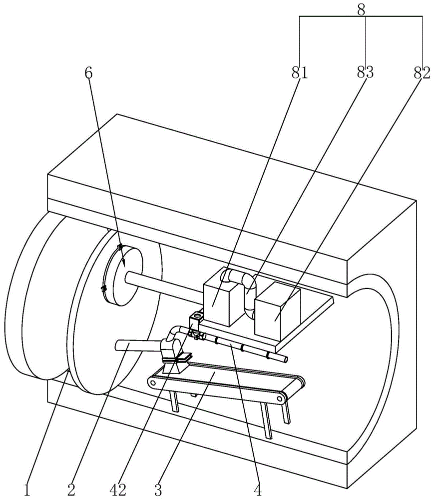
图1是本发明的结构示意图;Fig. 1 is the structural representation of the present invention;
图2是旨在显示拼接组件的示意图;Figure 2 is a schematic diagram intended to show a spliced assembly;
图3是旨在显示二次喷浆装置的示意图。Figure 3 is a schematic diagram intended to show a secondary shotcrete device.
图中,1、土仓;2、螺旋输送机;3、皮带输送机;4、排浆管;41、单元管;42、控制阀;5、拼接组件;51、第一法兰;52、第二法兰;53、连接螺栓;54、连接螺母;55、密封垫;6、二次喷浆装置;61、通孔;62、高压喷头;63、喷板;631、喷腔;64、喷浆管;7、固定组件;71、固定块;72、固定螺栓;73、固定螺母;8、喷射装置;81、液箱;82、加压器;83、连接管;9、橡胶垫。In the figure, 1, soil bin; 2, screw conveyor; 3, belt conveyor; 4, slurry discharge pipe; 41, unit pipe; 42, control valve; 5, splicing assembly; 51, first flange; 52, 2nd flange; 53, connecting bolt; 54, connecting nut; 55, gasket; 6, secondary spraying device; 61, through hole; 62, high pressure nozzle; 63, spray plate; 631, spray cavity; 64, Shotcrete pipe; 7. Fixing component; 71. Fixing block; 72. Fixing bolt; 73. Fixing nut; 8. Injection device; 81. Liquid tank; 82. Compressor; 83. Connecting pipe;
具体实施方式Detailed ways
以下结合附图对本发明作进一步详细说明。The present invention will be further described in detail below with reference to the accompanying drawings.
参照图1,为本发明公开的一种盾构出土防喷装置,包括土仓1、螺旋输送机2和皮带输送机3,螺旋输送机2倾斜设置,螺旋输送机2低的一端与土仓1的侧壁固定连接且连通,另一端固定连接有下料槽,下料槽内设置有闸门,闸门与下料槽滑动连接,下料槽远离螺旋输送机2的一端与皮带输送机3连接,螺旋输送机2靠近皮带输送机3的一端固定连接有排浆管4,排浆管4与螺旋输送机2的内部连通,排浆管4远离螺旋输送机2的一端延伸出盾构机,土仓1靠近螺旋输送机2的一侧设置有二次喷浆装置6。使用盾构机时,首先将二次喷浆装置6与土仓1的侧壁连接,然后再将排浆管4与螺旋输送机2连接固定,当盾构机发生泥浆喷涌时,马上关闭下料槽内的闸门,使螺旋输送机2内的泥浆进入排浆管4内,然后再利用二次喷浆装置6向土仓1内灌注膨润土或者发泡剂,改善土仓1内的土质,避免喷涌现象的加剧,同时利用排浆管4排出泥浆,避免盾构机由于无法排土导致停机,达到提升施工进度的目的。Referring to Fig. 1, it is a shield excavation blowout prevention device disclosed by the present invention, comprising a soil bin 1, a screw conveyor 2 and a belt conveyor 3. The screw conveyor 2 is inclined and the lower end of the screw conveyor 2 is connected to the soil bin. The side wall of 1 is fixedly connected and connected, the other end is fixedly connected with a feeding chute, a gate is arranged in the feeding chute, the gate is slidingly connected with the feeding chute, and one end of the feeding chute away from the screw conveyor 2 is connected with the belt conveyor 3 , one end of the screw conveyor 2 close to the belt conveyor 3 is fixedly connected with a slurry discharge pipe 4, the slurry discharge pipe 4 is communicated with the interior of the screw conveyor 2, and the end of the slurry discharge pipe 4 away from the screw conveyor 2 extends out of the shield machine, The side of the soil bin 1 close to the screw conveyor 2 is provided with a
参照图1和图2,排浆管4包括若干个单元管41,靠近螺旋输送机2的单元管41上固定连接有控制阀42,控制阀42常处于密闭状态,相邻单元管41之间设置有拼接组件5,相邻单元管41之间通过拼接组件5相互连通;拼接组件5包括拼接法兰、连接螺栓53和连接螺母54,拼接法兰包括第一法兰51和第二法兰52,第一法兰51与单元管41的一端固定连接,第二法兰52与相邻的单元管41的一端固定连接,第一法兰51与第二法兰52之间设置有密封垫55,密封垫55的两侧分别与第一法兰51和第二法兰52抵接,连接螺栓53的一端穿过第一法兰51、密封垫55和第二法兰52后与连接螺母54螺纹连接,连接螺母54与第二法兰52抵接。连接排浆管4时,首先移动单元管41,使单元管41带动第一法兰51靠近相邻单元管41的第二法兰52,然后再第一法兰51和第二法兰52之间放置密封垫55,再将连接螺栓53的一端穿过第一法兰51、第二法兰52和密封垫55后与连接螺母54螺纹连接,使第一法兰51和第二法兰52固定,依次连接若干个单元管41,完成排浆管4的安装。1 and 2, the slurry discharge pipe 4 includes several unit pipes 41, and a
参照图1和图3,二次喷浆装置6包括通孔61、高压喷头62、喷板63和喷浆管64,通孔61设置有若干个,每个通孔61均垂直土仓1的侧壁,每个通孔61均贯穿土仓1的侧壁,高压喷头62设置有若干个,每个通孔61内均固定连接一个高压喷头62,若干个高压喷头62远离土仓1的一端均与喷板63固定连接,喷板63内开设有喷腔631,喷腔631与每个高压喷头62均连通;喷板63与土仓1的侧壁之间设置有固定组件7,固定组件7包括固定块71、固定螺栓72和固定螺母73,固定块71设置有四个,四个固定块71沿喷板63的边缘均匀设置,四个固定块71均与喷板63固定连接,固定螺栓72设置有四个,四个固定螺螺与四个固定块71对应设置,四个固定螺栓72的一端均与土仓1的侧壁固定连接,另一端分别穿过四个固定块71后,每个固定螺栓72均与一个固定螺母73螺纹连接。1 and 3, the
参照图1和图3,喷板63与土仓1的侧壁之间设置有橡胶垫9,橡胶垫9与喷板63固定连接,橡胶垫9远离喷板63的一侧与土仓1的侧壁抵接,喷板63远离橡胶垫9的一侧与喷浆管64固定连接,喷浆管64与喷腔631连通;喷浆管64远离喷板63的一端连接有喷射装置8,喷射装置8包括液箱81、加压器82和连接管83,液箱81和加压器82均与盾构机的侧壁固定连接,液箱81与喷浆管64远离喷板63的一端固定连接且连通,连接管83设置在加压器82与液箱81之间,连接管83的两端分别与加压器82和液箱81固定连接,加压器82通过连接管83与液箱81连通。安装二次喷浆装置6时,首先移动喷板63靠近土仓1的侧壁,使喷板63带动高压喷头62插入通孔61内,喷板63带动橡胶垫9和固定块71与土仓1的侧壁抵接,固定螺栓72的一端穿过固定块71与固定螺母73螺纹连接,使喷板63与土仓1的侧壁固定;当使用二次喷浆装置6时,首先启动加压器82,加压器82将液箱81内的膨润土或者发泡剂压至喷浆管64内,然后通过喷腔631进入若干个高压喷头62内,利用高压喷头62将膨润土或者发泡剂喷至土仓1内,改善土仓1内土的土质。1 and 3, a rubber pad 9 is provided between the spray plate 63 and the side wall of the soil bin 1, the rubber pad 9 is fixedly connected with the spray plate 63, and the side of the rubber pad 9 away from the spray plate 63 is connected to the side of the soil bin 1. The side wall abuts, the side of the spray plate 63 away from the rubber pad 9 is fixedly connected with the
本实施例的实施原理为:盾构机使用前,首先进行二次喷浆装置6的安装,首先移动喷板63带动高压喷头62插入通孔61内,喷板63带动橡胶垫9和固定块71与土仓1的侧壁抵接,使固定螺栓72远离土仓1侧壁的一端穿过固定块71后再与固定螺母73螺纹连接,使喷板63与土仓1的侧壁固定,再将每个高压喷头62均与通孔61的侧壁固定连接,完成二次喷浆装置6的安装;然后移动一根单元管41带动第二法兰52与相邻单元的第一法兰51靠近,然后在第一法兰51和第二法兰52之间放置密封垫55,再使连接螺栓53的一端穿过第一法兰51、第二法兰52和密封垫55后与连接螺母54螺纹连接,重复上述步骤,完成排浆管4的组装,然后开始利用盾构机进行挖掘。The implementation principle of this embodiment is: before the shield machine is used, firstly install the secondary spraying device 6, first move the spraying plate 63 to drive the high-pressure spray head 62 into the through hole 61, and the spraying plate 63 drives the rubber pad 9 and the fixing block 71 is in contact with the side wall of the soil bin 1, so that the end of the fixing bolt 72 away from the side wall of the soil bin 1 passes through the fixing block 71 and then is screwed with the fixing nut 73, so that the spray plate 63 is fixed with the side wall of the soil bin 1, Then each high-pressure nozzle 62 is fixedly connected to the side wall of the through hole 61 to complete the installation of the secondary spraying device 6; then move a unit pipe 41 to drive the second flange 52 and the first flange of the adjacent unit 51 close, and then place a gasket 55 between the first flange 51 and the second flange 52, and then make one end of the connecting bolt 53 pass through the first flange 51, the second flange 52 and the gasket 55 and connect with the The nut 54 is threadedly connected, and the above steps are repeated to complete the assembly of the slurry discharge pipe 4, and then start to excavate with the shield machine.
当挖掘过程中发生泥浆喷涌时,首先将下料槽处的闸门关闭,然后打开控制阀42使排浆管4与螺旋输送机2连通,泥浆通过排浆管4排出盾构机;然后再启动加压器82,利用连接管83使加压器82与液箱81连通,使液箱81内的膨润土或者发泡剂压至喷浆管64内,膨润土或者发泡剂通过喷浆管64进入喷腔631内后,再通过高压喷头62喷入土仓1内,利用膨润土或者发泡剂对土仓1内的土质进行改善,避免泥浆喷涌的加剧,使盾构机不需要停机进行泥沙清理的工作,综上,通过上述步骤,达到提升施工进度的目的。When the mud gushing occurs during the excavation process, first close the gate at the discharge chute, then open the
本具体实施方式的实施例均为本发明的较佳实施例,并非依此限制本发明的保护范围,故:凡依本发明的结构、形状、原理所做的等效变化,均应涵盖于本发明的保护范围之内。The embodiments of this specific embodiment are all preferred embodiments of the present invention, and are not intended to limit the protection scope of the present invention. Therefore: all equivalent changes made according to the structure, shape and principle of the present invention should be covered in within the protection scope of the present invention.
Claims (8)
Priority Applications (1)
| Application Number | Priority Date | Filing Date | Title |
|---|---|---|---|
| CN202010470656.5A CN111706339B (en) | 2020-05-28 | 2020-05-28 | Shield constructs out-of-earth blowout preventer |
Applications Claiming Priority (1)
| Application Number | Priority Date | Filing Date | Title |
|---|---|---|---|
| CN202010470656.5A CN111706339B (en) | 2020-05-28 | 2020-05-28 | Shield constructs out-of-earth blowout preventer |
Publications (2)
| Publication Number | Publication Date |
|---|---|
| CN111706339A true CN111706339A (en) | 2020-09-25 |
| CN111706339B CN111706339B (en) | 2021-11-23 |
Family
ID=72538352
Family Applications (1)
| Application Number | Title | Priority Date | Filing Date |
|---|---|---|---|
| CN202010470656.5A Active CN111706339B (en) | 2020-05-28 | 2020-05-28 | Shield constructs out-of-earth blowout preventer |
Country Status (1)
| Country | Link |
|---|---|
| CN (1) | CN111706339B (en) |
Citations (7)
| Publication number | Priority date | Publication date | Assignee | Title |
|---|---|---|---|---|
| JPH05202693A (en) * | 1992-01-23 | 1993-08-10 | Ohbayashi Corp | Mechanical shield excavation method using foaming agent |
| CN202469300U (en) * | 2012-03-13 | 2012-10-03 | 贵州省水利水电勘测设计研究院 | Connection structure between two grout pipes |
| CN104879133A (en) * | 2015-05-21 | 2015-09-02 | 中铁工程装备集团有限公司 | Double-mode shield tunneling machine |
| CN204783040U (en) * | 2015-07-06 | 2015-11-18 | 中铁工程装备集团有限公司 | Prevent twin screw conveyor that gushs |
| CN106437742A (en) * | 2016-09-05 | 2017-02-22 | 中铁十六局集团北京轨道交通工程建设有限公司 | Earth pressure balance shield construction uprush control device and method in water-rich surrounding rock |
| CN108952746A (en) * | 2018-07-26 | 2018-12-07 | 中建隧道建设有限公司 | Anti-spouting device, application method and screw conveyor |
| CN209855804U (en) * | 2019-04-29 | 2019-12-27 | 河南工程学院 | A kind of slag discharge system of air cushion type slurry shield machine |
-
2020
- 2020-05-28 CN CN202010470656.5A patent/CN111706339B/en active Active
Patent Citations (7)
| Publication number | Priority date | Publication date | Assignee | Title |
|---|---|---|---|---|
| JPH05202693A (en) * | 1992-01-23 | 1993-08-10 | Ohbayashi Corp | Mechanical shield excavation method using foaming agent |
| CN202469300U (en) * | 2012-03-13 | 2012-10-03 | 贵州省水利水电勘测设计研究院 | Connection structure between two grout pipes |
| CN104879133A (en) * | 2015-05-21 | 2015-09-02 | 中铁工程装备集团有限公司 | Double-mode shield tunneling machine |
| CN204783040U (en) * | 2015-07-06 | 2015-11-18 | 中铁工程装备集团有限公司 | Prevent twin screw conveyor that gushs |
| CN106437742A (en) * | 2016-09-05 | 2017-02-22 | 中铁十六局集团北京轨道交通工程建设有限公司 | Earth pressure balance shield construction uprush control device and method in water-rich surrounding rock |
| CN108952746A (en) * | 2018-07-26 | 2018-12-07 | 中建隧道建设有限公司 | Anti-spouting device, application method and screw conveyor |
| CN209855804U (en) * | 2019-04-29 | 2019-12-27 | 河南工程学院 | A kind of slag discharge system of air cushion type slurry shield machine |
Also Published As
| Publication number | Publication date |
|---|---|
| CN111706339B (en) | 2021-11-23 |
Similar Documents
| Publication | Publication Date | Title |
|---|---|---|
| CN103470297B (en) | One is bored, takes out, is arranged integrated coal seam pressure relief permeability improvement device and using method thereof | |
| CN102561977B (en) | High-pressure high-flow water burst hole drilling safety system, mounting process thereof and service process | |
| CN113266391B (en) | Wall rear buffer air bag device for preventing pipe piece from floating upwards and construction method thereof | |
| CN108952746B (en) | Gushing prevention device, using method and spiral conveyor | |
| CN104389559A (en) | Method and device for preventing and controlling gas transfinite in thick-coal-seam mining process | |
| CN102345465A (en) | Hooping sealing device used in shield arrival | |
| WO2021078195A1 (en) | Monitoring meter installing device and installing method | |
| CN206495676U (en) | A kind of pre-buried aperture tubular construction of freezing process | |
| CN221092130U (en) | Anti-blocking device for carbon powder feeding hole | |
| CN205778894U (en) | A kind of shield spiral mouth controls the device of mud | |
| CN111706339A (en) | A kind of shield unearthed blowout preventer | |
| CN109973047B (en) | A low-concentration through-bed drainage drilling recovery type hole sealer and its repair method | |
| CN210031786U (en) | Large-diameter rock drilling and filling device | |
| CN102776905A (en) | Grouting stoppage and guide repair method for leakage of deformation joint and special grouting device for grouting stoppage and guide repair method for leakage of deformation joint | |
| CN215170046U (en) | Quick connecting joint device and sealing device for grouting of advanced small tunnel conduit | |
| CN212001116U (en) | Orifice closures for curtain grouting | |
| CN113738440A (en) | Method and device for processing paste filling pipeline | |
| CN202370529U (en) | Reinforcement structure of tunnel surface in shield machine cabin | |
| CN113738386A (en) | Leakage blocking method for normal-pressure cutter barrel of shield machine under high-water-pressure condition | |
| CN111622782A (en) | PVC pipe hole bottom grouting device and installation and grouting method thereof | |
| CN207213171U (en) | A kind of push-bench export & import sealing device | |
| CN117049021A (en) | Anti-clogging device and method for toner feed port | |
| CN104989451B (en) | A kind of method that use weather board administers operation tunnel leak | |
| CN206319885U (en) | Earth pressure balanced shield, EPBS construction is prominent in a kind of rich water country rock gushes preventing and treating device | |
| CN109707337A (en) | Assembled grouting pipe voluntarily slurry stop |
Legal Events
| Date | Code | Title | Description |
|---|---|---|---|
| PB01 | Publication | ||
| PB01 | Publication | ||
| SE01 | Entry into force of request for substantive examination | ||
| SE01 | Entry into force of request for substantive examination | ||
| GR01 | Patent grant | ||
| GR01 | Patent grant | ||
| PP01 | Preservation of patent right |
Effective date of registration: 20250805 Granted publication date: 20211123 |
|
| PP01 | Preservation of patent right |