Shield constructs out-of-earth blowout preventer
Technical Field
The invention relates to the technical field of tunnel excavation of shield tunneling machines, in particular to a shield unearthing blowout preventer.
Background
At present, with the rapid development of cities, subways have greater and greater effects in urban traffic, and shield machines are commonly used for excavating underground tunnels in subway construction.
The existing shield machine comprises a soil bin, a screw conveyor and a belt conveyor, wherein the screw conveyor is fixedly connected with the side wall of the soil bin, the screw conveyor is communicated with the inside of the soil bin, and one end, far away from the soil bin, of the screw conveyor is connected with the belt conveyor. Soil in the soil bin is conveyed to the belt conveyor through the screw conveyor, and then the belt conveyor is used for enabling the muck to be far away from the screw conveyor.
The above prior art solutions have the following drawbacks: when the shield machine causes gushing muddy water due to pressure difference, a large amount of silt is sprayed on the belt conveyor along with water flow, even a small amount of muddy water gushes, the silt slides down from the belt conveyor, the unearthing is difficult, the shield machine has to be stopped for silt cleaning work in construction, and the construction progress is slow.
Disclosure of Invention
Aiming at the defects in the prior art, the invention aims to provide a shield unearthing blowout preventer to achieve the purpose of improving the construction progress.
The above object of the present invention is achieved by the following technical solutions:
the utility model provides a shield constructs unearthed blowout preventer, includes soil storehouse, screw conveyer and band conveyer, screw conveyer's one end and the lateral wall fixed connection and the intercommunication in soil storehouse, and the other end is connected and communicates with band conveyer, screw conveyer is close to band conveyer's one end fixedly connected with mud discharging pipe, mud discharging pipe and screw conveyer intercommunication, fixedly connected with control valve on the mud discharging pipe, and the one end that screw conveyer was kept away from to the mud discharging pipe extends the shield and constructs the machine, and the control valve is often in airtight state, and one side that soil storehouse is close to band conveyer is provided with the secondary whitewashing device.
By adopting the technical scheme, when the detection mechanism detects that the shield machine gushes muddy water, the gate at the joint of the screw conveyer and the belt conveyer is closed, then the control valve is opened, the screw conveyer is communicated with the slurry discharge pipe, at the moment, the slurry in the screw conveyer is conveyed into the slurry discharge pipe, and the end of the slurry discharge pipe, which is far away from the control valve, extends out of the shield machine, so that the slurry is discharged out of the shield machine and then is transported by a vehicle; meanwhile, bentonite or foaming agent is conveyed into the soil bin by using the secondary guniting device, and the workability of soil quality in the soil bin is improved by using the bentonite or the foaming agent, so that soil and slurry in the soil bin are integrated, a screw conveyor is convenient to discharge, and the deterioration of a gushing phenomenon is avoided; the discharge of whitewashing is carried out through setting up the mud discharging pipe, recycles the soil property in the secondary whitewashing device and the soil storehouse, and silt band conveyer slides down on the top when avoiding the whitewashing, need not shut down the work of carrying out silt clearance, reaches the purpose that promotes the construction progress.
The present invention in a preferred example may be further configured to: the pulp discharge pipe comprises a plurality of unit pipes, adjacent unit pipes are connected with each other, and a splicing assembly is arranged between the adjacent unit pipes.
Through adopting above-mentioned technical scheme, will arrange the thick liquid pipe and set up a plurality of unit pipe to set up the concatenation subassembly between adjacent unit pipe and connect, be convenient for control arranges the length of thick liquid pipe, promote the convenience when arranging thick liquid pipe and using.
The present invention in a preferred example may be further configured to: the splicing assembly comprises a splicing flange, a connecting bolt and a connecting nut, the splicing flange comprises a first flange and a second flange, the first flange is fixedly connected with one end of each unit pipe, the second flange is fixedly connected with one end of each adjacent unit pipe, the first flange is abutted against the second flange, and one end of the connecting bolt penetrates through the first flange and the second flange and is in threaded connection with the connecting nut.
Through adopting above-mentioned technical scheme, when adjacent row thick liquid union coupling, at first the unit pipe is close to adjacent unit pipe, then promote adjacent unit pipe, make adjacent unit pipe drive second flange and first flange butt, pass first flange and second flange back with connecting bolt's one end again with coupling nut threaded connection, it is fixed with the second flange to make first flange, accomplish the unit pipe and adjacent unit pipe between fixed, the concatenation subassembly simple structure, high durability and convenient installation, convenience when promoting unit union coupling.
The present invention in a preferred example may be further configured to: a sealing gasket is arranged between the first flange and the second flange, and a fixing bolt penetrates through the sealing gasket.
Through adopting above-mentioned technical scheme, through setting up sealed the pad, make sealed the gap between sealed first flange and the second flange, promote the leakproofness between first flange and the second flange.
The present invention in a preferred example may be further configured to: the secondary whitewashing device includes the through-hole, high pressure nozzle, spout board and whitewashing pipe, a plurality of has been seted up to the through-hole, every through-hole is all seted up at the lateral wall in soil storehouse and is run through the lateral wall in soil storehouse, high pressure nozzle of equal fixed connection in every through-hole, the one end that a plurality of high pressure nozzle kept away from soil storehouse all with spout board fixed connection, be provided with fixed subassembly between the lateral wall in spout board and soil storehouse, it spouts the chamber to have seted up in the spout board, every high pressure nozzle all with spout the chamber intercommunication, one side and the whitewashing pipe fixed connection that high pressure nozzle was kept away from to the spout board, whitewashing pipe and spouting chamber intercommunication, the one end that the whitewashing pipe kept away from the spout board is connected with injection apparatus.
By adopting the technical scheme, when the secondary guniting device is installed, the liquid tank and the pressurizer are fixedly connected with the shield tunneling machine, so that the stability of the liquid tank and the pressurizer in use is improved; then moving the spray plate to enable the spray plate to drive the high-pressure spray head to be inserted into the through hole, utilizing the fixing assembly to enable the spray plate to be fixedly connected with the side wall of the soil bin, then connecting and fixing the high-pressure spray head with the through hole, finally utilizing the guniting pipe to connect the spray plate with the spraying device, and when secondary grouting is carried out, firstly utilizing the spraying device to spray bentonite or a foaming agent into the guniting pipe, wherein the guniting pipe is communicated with a spray cavity in the spray plate, so that the bentonite or the foaming agent enters the spray cavity after passing through the guniting pipe; because spout the chamber and communicate with high pressure nozzle, so bentonite or foamer through spouting the chamber after getting into in the high pressure nozzle, spout to the soil storehouse in, secondary slip casting device is through setting up spout the board with spout the chamber, realize that a plurality of shower nozzle sprays the purpose of bentonite or foamer simultaneously.
The present invention in a preferred example may be further configured to: the fixed assembly comprises a fixed block and a fixed bolt, the fixed block is fixedly connected with the spraying plate, one end of the fixed bolt is fixedly connected with the soil bin, and the other end of the fixed bolt is in threaded connection with a fixed nut after penetrating through the fixed block.
Through adopting above-mentioned technical scheme, when using fixed subassembly, remove the spout board and move the lateral wall butt of fixed block and soil storehouse, make fixing bolt keep away from one end of soil storehouse lateral wall pass behind the fixed block with fixation nut threaded connection, utilize fixation nut to make the fixed block fixed with the lateral wall of soil storehouse, because fixed block and spout board fixed connection, so the fixed block drives the lateral wall of spouting board and soil storehouse and is connected fixedly, promotes the stability when spouting board and soil storehouse lateral wall and being connected.
The present invention in a preferred example may be further configured to: the injection device comprises a liquid tank, a pressurizer and a connecting pipe, wherein the liquid tank and the pressurizer are fixedly connected with the shield tunneling machine, the liquid tank is fixedly connected with the guniting pipe and communicated with the guniting pipe, the connecting pipe is arranged between the pressurizer and the liquid tank, and two ends of the connecting pipe are respectively fixedly connected with the pressurizer and the liquid tank and communicated with the pressurizer and the liquid tank.
By adopting the technical scheme, when the injection device is used, firstly, bentonite or foaming agent is filled into the liquid tank, then the liquid tank and the pressurizer are fixed and communicated by utilizing the connecting pipe, pressure is applied to the liquid tank by utilizing the pressurizer, so that the bentonite or the foaming agent in the liquid tank enters the grout spraying pipe, the feeding device for the grout spraying pipe is completed, and meanwhile, the pressurizer is utilized to provide power for the secondary grouting device.
The present invention in a preferred example may be further configured to: a rubber pad is arranged between the spraying plate and the side wall of the soil bin, and the rubber pad is fixedly connected with the spraying plate.
Through adopting above-mentioned technical scheme, through setting up the rubber pad, utilize the shock attenuation effect of rubber pad to reduce the influence of soil storehouse vibrations to spouting the board, further promote the stability of spouting the board.
In summary, the invention includes at least one of the following beneficial technical effects:
1. by arranging the slurry discharge pipe and the secondary slurry spraying device, the slurry discharged by the slurry discharge pipe is discharged, the secondary slurry spraying device is used for improving the soil quality in the soil bin, the machine does not need to be stopped for cleaning silt, and the purpose of improving the construction progress is achieved;
2. the slurry discharge pipes are arranged into a plurality of pipes, and the splicing assemblies are arranged between the adjacent slurry discharge pipes, so that the flexibility of the slurry discharge pipes in use is improved;
3. through set up fixed block and fixing bolt between the lateral wall at shower plate and soil storehouse, promote the stability when being connected between shower plate and the soil storehouse lateral wall.
Drawings
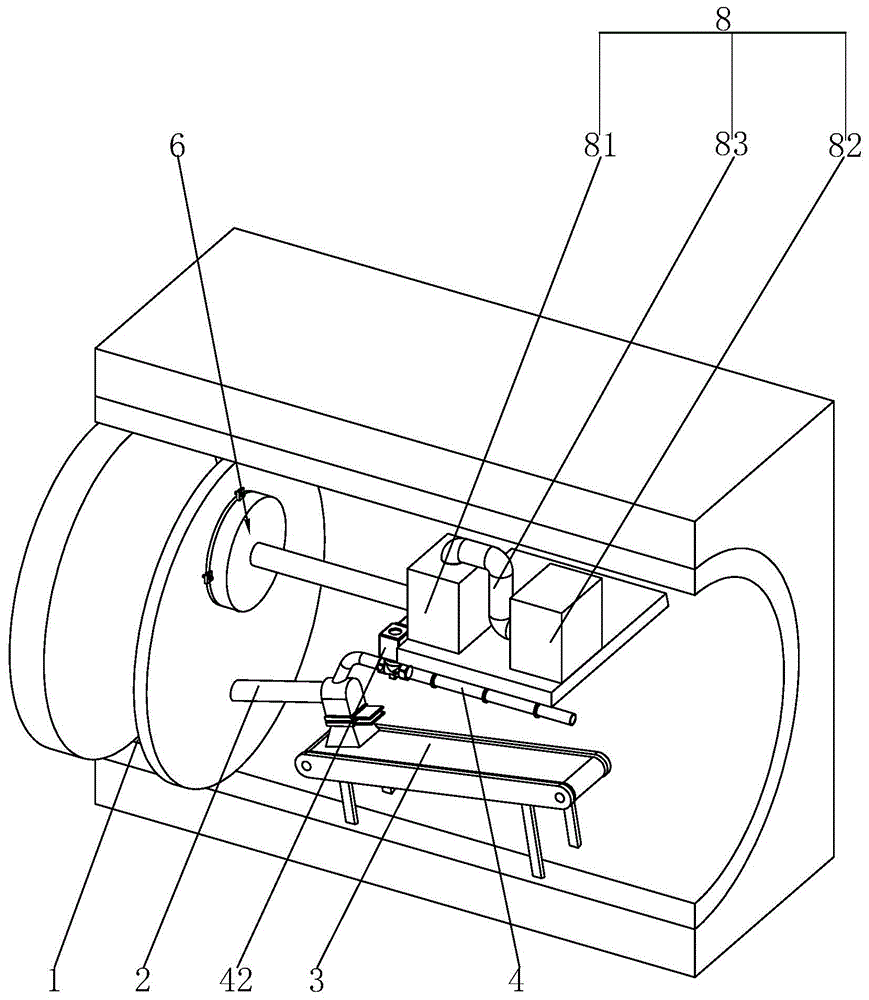
FIG. 1 is a schematic structural view of the present invention;
FIG. 2 is a schematic diagram intended to show a splice assembly;
fig. 3 is a schematic view intended to show a secondary guniting device.
In the figure, 1, a soil bin; 2. a screw conveyor; 3. a belt conveyor; 4. a slurry discharge pipe; 41. a unit pipe; 42. a control valve; 5. splicing the components; 51. a first flange; 52. a second flange; 53. a connecting bolt; 54. a connecting nut; 55. a gasket; 6. a secondary guniting device; 61. a through hole; 62. a high pressure spray head; 63. spraying a plate; 631. a spray chamber; 64. a guniting pipe; 7. a fixing assembly; 71. a fixed block; 72. fixing the bolt; 73. fixing a nut; 8. an injection device; 81. a liquid tank; 82. a pressurizer; 83. a connecting pipe; 9. and (7) a rubber pad.
Detailed Description
The present invention will be described in further detail with reference to the accompanying drawings.
Referring to fig. 1, the shield unearthing blowout preventer disclosed by the invention comprises a soil bin 1, a screw conveyor 2 and a belt conveyor 3, wherein the screw conveyor 2 is obliquely arranged, one lower end of the screw conveyor 2 is fixedly connected and communicated with the side wall of the soil bin 1, the other lower end of the screw conveyor 2 is fixedly connected with a blanking groove, a gate is arranged in the blanking groove and is in sliding connection with the blanking groove, one end of the blanking groove, which is far away from the screw conveyor 2, is connected with the belt conveyor 3, one end of the screw conveyor 2, which is close to the belt conveyor 3, is fixedly connected with a slurry discharge pipe 4, the slurry discharge pipe 4 is communicated with the inside of the screw conveyor 2, one end of the slurry discharge pipe 4, which is far away from the screw conveyor 2, extends out of the shield machine, and one side of the soil bin 1, which is close to the screw conveyor 2, is provided with a secondary slurry spraying device 6. When using the shield structure machine, at first be connected secondary whitewashing device 6 with the lateral wall in soil storehouse 1, then it is fixed to be connected with screw conveyer 2 with mud discharging pipe 4 again, when shield structure machine takes place the mud gush, close down the gate in the silo at once, make the mud in screw conveyer 2 get into mud discharging pipe 4 in, then reuse secondary whitewashing device 6 pours bentonite or foamer into soil storehouse 1, improve the soil property in the soil storehouse 1, avoid the aggravation of gushing the phenomenon, utilize mud discharging pipe 4 discharge mud simultaneously, avoid shield structure machine to lead to shutting down owing to unable soil discharging, reach the purpose that promotes the construction progress.
Referring to fig. 1 and 2, the slurry discharge pipe 4 includes a plurality of unit pipes 41, the unit pipes 41 close to the screw conveyor 2 are fixedly connected with control valves 42, the control valves 42 are always in a closed state, the splicing assemblies 5 are arranged between adjacent unit pipes 41, and the adjacent unit pipes 41 are communicated with each other through the splicing assemblies 5; splicing assembly 5 is including splicing the flange, connecting bolt 53 and coupling nut 54, splicing the flange and including first flange 51 and second flange 52, the one end fixed connection of first flange 51 and unit pipe 41, the one end fixed connection of second flange 52 and adjacent unit pipe 41, be provided with sealed pad 55 between first flange 51 and the second flange 52, the both sides of sealed pad 55 respectively with first flange 51 and second flange 52 butt, first flange 51 is passed to connecting bolt 53's one end, seal pad 55 and second flange 52 back and coupling nut 54 threaded connection, coupling nut 54 and second flange 52 butt. When the grout discharging pipe 4 is connected, the unit pipe 41 is firstly moved, the unit pipe 41 drives the first flange 51 to be close to the second flange 52 of the adjacent unit pipe 41, then the sealing gasket 55 is arranged between the first flange 51 and the second flange 52, one end of the connecting bolt 53 penetrates through the first flange 51, the second flange 52 and the sealing gasket 55 and then is in threaded connection with the connecting nut 54, the first flange 51 and the second flange 52 are fixed, the unit pipes 41 are sequentially connected, and the installation of the grout discharging pipe 4 is completed.
Referring to fig. 1 and 3, the secondary guniting device 6 comprises through holes 61, high-pressure nozzles 62, a gunning plate 63 and gunning pipes 64, wherein the through holes 61 are provided with a plurality of through holes 61, each through hole 61 is vertical to the side wall of the soil bin 1, each through hole 61 penetrates through the side wall of the soil bin 1, the high-pressure nozzles 62 are provided with a plurality of through holes 61, one high-pressure nozzle 62 is fixedly connected in each through hole 61, one ends of the high-pressure nozzles 62, far away from the soil bin 1, are fixedly connected with the gunning plate 63, a gunning cavity 631 is formed in the gunning plate 63, and the gunning cavity 631 is communicated with each high-pressure nozzle 62; spout and be provided with fixed subassembly 7 between the lateral wall of board 63 and soil storehouse 1, fixed subassembly 7 includes fixed block 71, fixing bolt 72 and fixation nut 73, fixed block 71 is provided with four, four fixed block 71 evenly set up along the edge of spouting board 63, four fixed block 71 all with spout board 63 fixed connection, fixing bolt 72 is provided with four, four fixed spiral shell correspond the setting with four fixed block 71, four fixing bolt 72's one end all with soil storehouse 1's lateral wall fixed connection, the other end passes four fixed block 71 backs respectively, every fixing bolt 72 all with a fixation nut 73 threaded connection.
Referring to fig. 1 and 3, a rubber pad 9 is arranged between the spray plate 63 and the side wall of the soil bin 1, the rubber pad 9 is fixedly connected with the spray plate 63, one side of the rubber pad 9, which is far away from the spray plate 63, is abutted against the side wall of the soil bin 1, one side of the spray plate 63, which is far away from the rubber pad 9, is fixedly connected with a guniting pipe 64, and the guniting pipe 64 is communicated with a guniting cavity 631; one end that the spout board 63 was kept away from to whitewashing pipe 64 is connected with injection apparatus 8, injection apparatus 8 includes liquid tank 81, presser 82 and connecting pipe 83, liquid tank 81 and presser 82 all with shield structure machine's lateral wall fixed connection, one end fixed connection and the intercommunication that spout board 63 was kept away from to liquid tank 81 and spouting pipe 64, connecting pipe 83 sets up between presser 82 and liquid tank 81, the both ends of connecting pipe 83 respectively with presser 82 and liquid tank 81 fixed connection, presser 82 communicates with liquid tank 81 through connecting pipe 83. When the secondary guniting device 6 is installed, firstly, the spraying plate 63 is moved to be close to the side wall of the soil bin 1, so that the spraying plate 63 drives the high-pressure nozzle 62 to be inserted into the through hole 61, the spraying plate 63 drives the rubber pad 9 and the fixed block 71 to be abutted against the side wall of the soil bin 1, one end of the fixed bolt 72 penetrates through the fixed block 71 to be in threaded connection with the fixed nut 73, and the spraying plate 63 is fixed with the side wall of the soil bin 1; when the secondary guniting device 6 is used, firstly, the pressurizer 82 is started, the pressurizer 82 presses bentonite or foaming agent in the liquid tank 81 into the guniting pipe 64, then the bentonite or foaming agent enters the high-pressure nozzles 62 through the spraying cavity 631, and the bentonite or foaming agent is sprayed into the soil bin 1 through the high-pressure nozzles 62, so that the soil quality of soil in the soil bin 1 is improved.
The implementation principle of the embodiment is as follows: before the shield machine is used, firstly, the secondary guniting device 6 is installed, firstly, the spraying plate 63 is moved to drive the high-pressure nozzles 62 to be inserted into the through holes 61, the spraying plate 63 drives the rubber pad 9 and the fixing block 71 to be abutted against the side wall of the soil bin 1, one end, far away from the side wall of the soil bin 1, of the fixing bolt 72 penetrates through the fixing block 71 and then is in threaded connection with the fixing nut 73, the spraying plate 63 is fixed with the side wall of the soil bin 1, and then each high-pressure nozzle 62 is fixedly connected with the side wall of the through hole 61, so that the installation of the secondary guniting device 6 is completed; then, moving one unit pipe 41 to drive the second flange 52 to be close to the first flange 51 of the adjacent unit, then placing a sealing gasket 55 between the first flange 51 and the second flange 52, enabling one end of a connecting bolt 53 to penetrate through the first flange 51, the second flange 52 and the sealing gasket 55 and then to be in threaded connection with a connecting nut 54, repeating the steps, completing the assembly of the slurry discharge pipe 4, and then beginning to dig by using a shield machine.
When the slurry gushes in the excavation process, firstly, the gate at the discharging groove is closed, then the control valve 42 is opened to enable the slurry discharge pipe 4 to be communicated with the screw conveyer 2, and the slurry is discharged out of the shield machine through the slurry discharge pipe 4; then the pressurizer 82 is started again, the pressurizer 82 is communicated with the liquid tank 81 through the connecting pipe 83, bentonite or foaming agent in the liquid tank 81 is pressed into the slurry spraying pipe 64, the bentonite or the foaming agent enters the spraying cavity 631 through the slurry spraying pipe 64 and then is sprayed into the soil bin 1 through the high-pressure sprayer 62, soil quality in the soil bin 1 is improved through the bentonite or the foaming agent, aggravation of slurry spraying is avoided, the shield tunneling machine does not need to be stopped to perform silt cleaning, and in sum, through the steps, the purpose of improving the construction progress is achieved.
The embodiments of the present invention are preferred embodiments of the present invention, and the scope of the present invention is not limited by these embodiments, so: all equivalent changes made according to the structure, shape and principle of the invention are covered by the protection scope of the invention.