CN111745580A - a wrench - Google Patents
a wrench Download PDFInfo
- Publication number
- CN111745580A CN111745580A CN202010037995.4A CN202010037995A CN111745580A CN 111745580 A CN111745580 A CN 111745580A CN 202010037995 A CN202010037995 A CN 202010037995A CN 111745580 A CN111745580 A CN 111745580A
- Authority
- CN
- China
- Prior art keywords
- wrench
- clamping
- hook
- clamping part
- rod
- Prior art date
- Legal status (The legal status is an assumption and is not a legal conclusion. Google has not performed a legal analysis and makes no representation as to the accuracy of the status listed.)
- Granted
Links
Images


Classifications
-
- B—PERFORMING OPERATIONS; TRANSPORTING
- B25—HAND TOOLS; PORTABLE POWER-DRIVEN TOOLS; MANIPULATORS
- B25B—TOOLS OR BENCH DEVICES NOT OTHERWISE PROVIDED FOR, FOR FASTENING, CONNECTING, DISENGAGING, OR HOLDING
- B25B13/00—Spanners; Wrenches
- B25B13/56—Spanner sets
-
- B—PERFORMING OPERATIONS; TRANSPORTING
- B25—HAND TOOLS; PORTABLE POWER-DRIVEN TOOLS; MANIPULATORS
- B25B—TOOLS OR BENCH DEVICES NOT OTHERWISE PROVIDED FOR, FOR FASTENING, CONNECTING, DISENGAGING, OR HOLDING
- B25B13/00—Spanners; Wrenches
- B25B13/46—Spanners; Wrenches of the ratchet type, for providing a free return stroke of the handle
- B25B13/461—Spanners; Wrenches of the ratchet type, for providing a free return stroke of the handle with concentric driving and driven member
- B25B13/462—Spanners; Wrenches of the ratchet type, for providing a free return stroke of the handle with concentric driving and driven member the ratchet parts engaging in a direction radial to the tool operating axis
- B25B13/463—Spanners; Wrenches of the ratchet type, for providing a free return stroke of the handle with concentric driving and driven member the ratchet parts engaging in a direction radial to the tool operating axis a pawl engaging an externally toothed wheel
Landscapes
- Engineering & Computer Science (AREA)
- Mechanical Engineering (AREA)
- Details Of Spanners, Wrenches, And Screw Drivers And Accessories (AREA)
Abstract
本发明公开了一种扳手,包括手柄部和夹紧部,手柄部一体连接有挡板,挡板卡设于夹紧部的外侧,夹紧部由内向外依次套设有复数个中空的卡件,卡件至少一个侧面设置有复数个钩体,钩体包括上钩体和下钩体,卡件至少一个侧面设置有复数个与钩体相适配的槽体,钩体与槽体处于相同或不同侧面,处于不同位置的钩体滑入或滑出槽体,实现相邻卡件的相对移动,夹紧部环绕最外侧卡件设置有棘轮转子,手柄部靠近夹紧部的一端设置有与棘轮转子配合使用以实现棘轮转子正、反转的传动件。本发明的扳手既可以实现开口大小可调,对不同尺寸的待旋部件进行拧紧或拧松操作,又可以实现连续扳动待旋部件,无需在扳动待旋部件的过程中离开待旋部件,提高工作效率。

The invention discloses a wrench, which comprises a handle part and a clamping part. The handle part is integrally connected with a baffle plate, the baffle plate is clamped on the outer side of the clamping part, and the clamping part is sequentially sleeved with a plurality of hollow clamps from the inside to the outside. At least one side of the clip is provided with a plurality of hook bodies, the hook body includes an upper hook body and a lower hook body, and at least one side of the clip is provided with a plurality of groove bodies that are adapted to the hook bodies, and the hook bodies and the groove body are in the same position. Or on different sides, the hooks at different positions slide into or out of the groove to realize the relative movement of the adjacent clips. The clamping part is provided with a ratchet rotor around the outermost clip, and the end of the handle part close to the clamping part is provided with a ratchet rotor. It is used in conjunction with the ratchet rotor to realize the forward and reverse rotation of the ratchet rotor. The wrench of the present invention can realize adjustable opening size, tighten or loosen the parts to be rotated with different sizes, and can continuously pull the parts to be rotated without leaving the parts to be rotated in the process of pulling the parts to be rotated ,Improve work efficiency.
Description
技术领域technical field
本发明涉及手动工具,特别是涉及一种扳手。The present invention relates to hand tools, in particular to a wrench.
背景技术Background technique
目前生产生活中常用的扳手主要有呆扳手、活扳手、棘轮扳手等几种类型。呆扳手的一端或两端制有固定尺寸的开口,一个扳手无法适应多种规格工作需要,因此会制成多种规格,复杂工作需要携带多把才行。活扳手的开口宽度可在一定尺寸范围内进行调节,能拧转不同规格的螺栓或螺母,但是现有的活扳手,其手柄只能转动较小的角度,因此需要对工件进行连续多次转动,才能旋紧或旋松。在两次旋动之间,需要停顿下来将扳手反方向回转,通常的做法是将扳手脱离工件,回转后再次套上重新旋动,这种操作方法十分不便,旋动效率较低。棘轮把手能够简化这种操作,旋动之间,无需将扳手从工件上脱离即可回转,但是常见的棘轮扳手的开口大小固定,无法进行调节,非常不方便。如果要将棘轮结构与开口可调结合在一起时难度又会比较大。At present, there are several types of wrenches commonly used in production and life, such as fixed wrenches, adjustable wrenches, and ratchet wrenches. One or both ends of the wrench have a fixed size opening. One wrench cannot meet the needs of various specifications of work, so it will be made into various specifications, and complex work needs to carry more than one. The opening width of the adjustable wrench can be adjusted within a certain size range, and it can rotate bolts or nuts of different specifications, but the handle of the existing adjustable wrench can only be rotated by a small angle, so the workpiece needs to be rotated continuously for many times. , can be tightened or loosened. Between two rotations, it is necessary to stop and rotate the wrench in the opposite direction. The usual method is to separate the wrench from the workpiece, and then put it on again and rotate it again. This operation method is very inconvenient and the rotation efficiency is low. The ratchet handle can simplify this operation. During rotation, the wrench can be rotated without disengaging the wrench from the workpiece. However, the opening size of the common ratchet wrench is fixed and cannot be adjusted, which is very inconvenient. It is more difficult to combine the ratchet structure with the adjustable opening.
发明内容SUMMARY OF THE INVENTION
为了解决现有活扳手开口可调,但需要暂时脱离工件才能回转,并重新套置进行旋动,操作麻烦且效率低的问题,本发明的目的是提供一种扳手,该扳手的开口大小可调,且不用脱离工件即可进行连续快速回转,不但适用于外六角部件,也适用于内六角部件,操作简单,提高了工作效率。In order to solve the problem that the opening of the existing adjustable wrench is adjustable, but it needs to be temporarily detached from the workpiece before it can be rotated and then re-sleeved to rotate, which is troublesome to operate and has low efficiency, the purpose of the present invention is to provide a wrench whose opening size can be adjusted It can be adjusted continuously and quickly without leaving the workpiece. It is not only suitable for outer hexagonal parts, but also for inner hexagonal parts. The operation is simple and the work efficiency is improved.
为了实现上述目的,本发明采用如下技术方案:一种扳手,包括手柄部和夹紧部,所述手柄部一体连接有挡板,所述挡板卡设于夹紧部的外侧,所述夹紧部由内向外依次套设有复数个中空的卡件,所述卡件至少一个侧面设置有复数个钩体,所述钩体包括上钩体和下钩体,所述卡件至少一个侧面设置有复数个与钩体相适配的槽体,所述钩体与槽体处于相同或不同侧面,处于不同位置的钩体滑入或滑出槽体,实现相邻卡件的相对移动,所述夹紧部环绕最外侧卡件设置有棘轮转子,所述手柄部靠近夹紧部的一端设置有与棘轮转子配合使用以实现棘轮转子正、反转的传动件。In order to achieve the above purpose, the present invention adopts the following technical solutions: a wrench includes a handle part and a clamping part, the handle part is integrally connected with a baffle plate, the baffle plate is clamped on the outer side of the clamping part, and the clip The tightening part is sequentially sleeved with a plurality of hollow clips from the inside to the outside, at least one side of the clip is provided with a plurality of hooks, the hook includes an upper hook and a lower hook, and at least one side of the clip is provided with There are a plurality of groove bodies matched with the hook body, the hook body and the groove body are on the same or different sides, and the hook bodies at different positions slide into or out of the groove body to realize the relative movement of the adjacent clips, so The clamping part is provided with a ratchet rotor around the outermost clamping part, and one end of the handle part close to the clamping part is provided with a transmission part used in cooperation with the ratchet rotor to realize the forward and reverse rotation of the ratchet rotor.
其中,所述传动件包括柱体,位于柱体顶端设置有旋钮,柱体底端交叉套设有第一棘爪和第二棘爪,柱体一侧连接有固定杆,柱体另一侧连接有转动杆,手柄部靠近传动件的一侧设置有固定槽,固定杆位于固定槽内,并受外力作用在固定槽内来回移动,转动杆位于第一棘爪和第二棘爪之间,棘轮转子与第一棘爪或第二棘爪相啮合。Wherein, the transmission member includes a cylinder, a knob is arranged at the top of the cylinder, a first pawl and a second pawl are cross-sleeved at the bottom of the cylinder, a fixing rod is connected on one side of the cylinder, and the other side of the cylinder is A rotating rod is connected, a fixed groove is set on the side of the handle part close to the transmission part, the fixed rod is located in the fixed groove, and is moved back and forth in the fixed groove by external force, and the rotating rod is located between the first pawl and the second pawl , the ratchet rotor is engaged with the first pawl or the second pawl.
其中,所述夹紧部的外形为圆形,所述卡件的横截面为正六边形。Wherein, the outer shape of the clamping part is circular, and the cross section of the clamping part is a regular hexagon.
其中,所述上钩体和下钩体的连线与水平面垂直,所述槽体与上钩体或下钩体的位置相对应。Wherein, the connecting line of the upper hook body and the lower hook body is perpendicular to the horizontal plane, and the groove body corresponds to the position of the upper hook body or the lower hook body.
其中,所述钩体还包括凹体,所述凹体与槽体适配使用。Wherein, the hook body further includes a concave body, and the concave body is adapted to be used with the groove body.
其中,所述凹体与上钩体、下钩体的连线与水平面垂直,所述凹体位于上钩体与下钩体之间,所述槽体与凹体的位置相对应。Wherein, the connecting line between the concave body, the upper hook body and the lower hook body is perpendicular to the horizontal plane, the concave body is located between the upper hook body and the lower hook body, and the groove body corresponds to the position of the concave body.
其中,所述上钩体、下钩体分别与凹体的连线与水平面垂直,所述上钩体、下钩体位于不同的铅垂线上,所述槽体与凹体的位置相对应。Wherein, the connecting lines of the upper hook body and the lower hook body and the concave body are perpendicular to the horizontal plane, the upper hook body and the lower hook body are located on different vertical lines, and the groove body corresponds to the position of the concave body.
其中,所述夹紧部的上端一侧设置有腔体,所述夹紧部内还设置有连通所有卡件的通孔,所述腔体内设置有复数个紧固件,所述紧固件包括伸出端,伸出端一端连接第二弹簧,所述伸出端上端设置凸起,所述第二弹簧远离伸出端的一端固定于腔体。Wherein, a cavity is provided on the upper end side of the clamping part, a through hole connecting all the clamping parts is also arranged in the clamping part, and a plurality of fasteners are arranged in the cavity, and the fasteners include The protruding end, one end of the protruding end is connected to the second spring, the upper end of the protruding end is provided with a protrusion, and the end of the second spring away from the protruding end is fixed to the cavity.
其中,所述紧固件为1个,位于腔体的左侧或右侧。Wherein, there is one fastener, which is located on the left or right side of the cavity.
其中,所述紧固件为两个,左右相对设置,分别为第一紧固件和第二紧固件。Wherein, there are two fasteners, which are arranged opposite to left and right, and are respectively a first fastener and a second fastener.
其中,所述夹紧部内设置有贯穿所有卡件的空腔,贯穿所述空腔放置有螺杆,螺杆两端螺纹连接有螺母,所述螺母位于夹紧部最大卡件的外侧。Wherein, the clamping part is provided with a cavity penetrating all the clamping parts, a screw rod is placed through the cavity, and both ends of the screw rod are threadedly connected with a nut, and the nut is located outside the largest clamping part of the clamping part.
其中,所述夹紧部内设置有滑道和滑竿,所述滑道贯穿夹紧部一侧的卡件,所述滑竿的一端与滑道滑动连接,所述滑竿的另一端通过轴体与夹紧部活动连接。Wherein, the clamping part is provided with a slideway and a slide rod, the slideway runs through the clamping part on one side of the clamping part, one end of the slide rod is slidably connected with the slideway, and the other end of the slide rod is connected to the clamp through the shaft body Tightly active connection.
夹紧部内还设置有滑竿,滑竿一端位于滑道内,并受外力作用在滑道内来回移动。A sliding rod is also arranged in the clamping part, and one end of the sliding rod is located in the slideway and moves back and forth in the slideway under the action of external force.
其中,所述夹紧部内设置有杆体,杆体位于所有卡件的外侧,杆体上、下两端分别活动连接有上滑片和下滑片,上滑片、下滑片卡于夹紧部的上下两端。Wherein, the clamping part is provided with a rod body, the rod body is located on the outer side of all the clamping parts, the upper and lower ends of the rod body are respectively movably connected with an upper sliding piece and a sliding piece, and the upper sliding piece and the lower piece are clamped on the upper and lower sides of the clamping part. end.
与现有技术相比,本发明实现的有益效果:本发明的扳手既可以实现开口大小可调,对不同尺寸的待旋部件进行拧紧或拧松操作,又可以实现连续扳动待旋部件,无需在扳动待旋部件的过程中离开待旋部件,提高工作效率;本发明的扳手通过相邻卡件钩体与槽体的配合使用,可以根据实际需要伸出卡件,不但适用于外六角部件,也适用于内六角部件,控制过程简单、方便。Compared with the prior art, the present invention has the beneficial effects: the wrench of the present invention can realize adjustable opening size, tighten or loosen the parts to be rotated with different sizes, and can continuously pull the parts to be rotated, There is no need to leave the to-be-rotated part in the process of pulling the to-be-rotated part, which improves work efficiency; the wrench of the present invention can be used in conjunction with the hook body of the adjacent clip and the groove body, and the clip can be extended according to actual needs, which is not only suitable for external Hexagonal parts are also suitable for inner hexagonal parts, and the control process is simple and convenient.
附图说明Description of drawings
以下结合附图和具体实施方式来进一步详细说明本发明:The present invention will be described in further detail below in conjunction with the accompanying drawings and specific embodiments:
图1为本发明实施例1公开的扳手的俯视图;1 is a top view of the wrench disclosed in
图2为本发明实施例1公开的扳手中相邻套件的连接关系图;Fig. 2 is the connection relationship diagram of adjacent sets in the wrench disclosed in
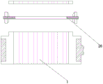
图3为本发明实施例1公开的扳手的主视图;3 is a front view of the wrench disclosed in
图4为图3中b-b方向的断面图;Fig. 4 is the sectional view of b-b direction in Fig. 3;
图5为本发明实施例1公开的扳手中传动件的结构示意图;5 is a schematic structural diagram of a transmission member in the wrench disclosed in
图6为本发明实施例1公开的扳手的使用状态图;Fig. 6 is the use state diagram of the wrench disclosed in
图7为本发明实施例2公开的扳手的俯视图;7 is a top view of the wrench disclosed in
图8为图7A处的局部放大图;Fig. 8 is a partial enlarged view at Fig. 7A;
图9为图8c-c方向上的断面图;Fig. 9 is a sectional view in the direction of Fig. 8 c-c;
图10为本发明实施例2公开的扳手第一使用状态的示意图;10 is a schematic diagram of the first use state of the wrench disclosed in
图11为本发明实施例2公开的扳手第二使用状态的示意图;11 is a schematic diagram of the second use state of the wrench disclosed in
图12本发明实施例3公开的扳手的主视图;Figure 12 is a front view of the wrench disclosed in Embodiment 3 of the present invention;
图13本发明实施例3公开的扳手的俯视图;Figure 13 is a top view of the wrench disclosed in Embodiment 3 of the present invention;
图14为图13d-d方向的断面图Fig. 14 is a sectional view in the direction of Fig. 13d-d
图15为本发明实施例3公开的扳手第一使用状态的示意图;15 is a schematic diagram of the first use state of the wrench disclosed in Embodiment 3 of the present invention;
图16为本发明实施例3公开的扳手第二使用状态的示意图;16 is a schematic diagram of the second use state of the wrench disclosed in Embodiment 3 of the present invention;
图17本发明实施例4公开的扳手的俯视图;Figure 17 is a top view of the wrench disclosed in Embodiment 4 of the present invention;
图18为图17e-e方向上的断面图;Figure 18 is a sectional view in the direction of Figure 17e-e;
图19本发明实施例5公开的扳手的主视图;Figure 19 is a front view of the wrench disclosed in
图20本发明实施例5公开的扳手的俯视图。FIG. 20 is a top view of the wrench disclosed in
其中:夹紧部1,卡件2,钩体3,棘轮转子5,手柄部6,传动件7,柱体8,旋钮9,第一棘爪10,第二棘爪11,固定杆12,转动杆13,固定槽14,腔体17,通孔18,紧固件19,伸出端20,第二弹簧21,凸起22,第一紧固件23,第二紧固件24,空腔25,螺杆26,滑道28,滑竿29,上滑片31,下滑片32,上钩体33,下钩体33-1,凹体34,槽体36,第一弹簧37。Among them: clamping
具体实施方式Detailed ways
以下由特定的具体实施例说明本发明的实施方式,熟悉此技术的人士可由本说明书所揭露的内容轻易地了解本发明的其他优点及功效。The embodiments of the present invention are described below by specific embodiments, and those skilled in the art can easily understand other advantages and effects of the present invention from the contents disclosed in this specification.
请参阅图1至图20。须知,本说明书所附图式所绘示的结构、比例、大小等,均仅用以配合说明书所揭示的内容,以供熟悉此技术的人士了解与阅读,并非用以限定本发明可实施的限定条件,故不具技术上的实质意义,任何结构的修饰、比例关系的改变或大小的调整,在不影响本发明所能产生的功效及所能达成的目的下,均应仍落在本发明所揭示的技术内容得能涵盖的范围内。同时,本说明书中所引用的如“上”、“下”、“左”、“右”、“中间”及“一”等的用语,亦仅为便于叙述的明了,而非用以限定本发明可实施的范围,其相对关系的改变或调整,在无实质变更技术内容下,当亦视为本发明可实施的范畴。See Figures 1 through 20. It should be noted that the structures, proportions, sizes, etc. shown in the drawings in this specification are only used to cooperate with the contents disclosed in the specification, so as to be understood and read by those who are familiar with the technology, and are not used to limit the implementation of the present invention. Restricted conditions, it does not have technical substantive significance, any structural modification, proportional relationship change or size adjustment, without affecting the effect that the present invention can produce and the purpose that can be achieved, should still fall within the present invention. The disclosed technical content must be within the scope of coverage. At the same time, the terms such as "up", "down", "left", "right", "middle" and "one" quoted in this specification are only for the convenience of description and clarity, and are not used to limit this specification. The implementable scope of the invention, and the change or adjustment of the relative relationship thereof, shall also be regarded as the implementable scope of the present invention without substantially changing the technical content.
实施例1Example 1
如图1、2,一种扳手,包括手柄部6和夹紧部1,夹紧部1的外形为圆形,手柄部6一体连接有挡板,挡板卡设于夹紧部1的外侧,夹紧部1由内向外依次套设有复数个中空的卡件2,卡件2的横截面为正六边形。卡件2不相邻的两个侧面上分别设置有钩体,钩体包括上钩体33、下钩体33-1和2个凹体34,此处的上钩体33自卡件2侧面向内、向下延伸,下钩体33-1自卡件2侧面向内、向上延伸,凹体34自卡件2侧面向内延伸形成一凹槽。上钩体33与一凹体34处于同一侧面,且上钩体33与凹体34的连线与水平面垂直,下钩体33-1与另一凹体34处于另一侧面,且下钩体33-1与凹体34的连线与水平面垂直,卡件2另两个不相邻的侧面上分别设置有槽体36,槽体36与对应的凹体34处于同一高度。As shown in Figures 1 and 2, a wrench includes a
在使用前,夹紧部1内各个卡件2相互紧套且处于同一个平面,此时凹体34分别位于槽体36内,当需要拧紧或拧松内六角的待旋部件,如螺帽、螺栓、螺钉、螺母时,根据待旋部件内六角的大小选择适当位置的卡件2,如卡件B,将与卡件B相邻的卡件2分别命名为卡件A、卡件C,卡件A位于卡件B的内侧,卡件C位于卡件B的外侧,向下按压由B向内的所有卡件(包括卡件B),将卡件B中的凹体34卡于卡件A中的槽体36,卡件C中的上钩体33卡于卡件B中槽体36,卡件B伸出夹紧部1,将待旋部件套于卡件B,对待旋部件进行拧紧或拧松操作。Before use, the clamping
在实际操作中,卡件B可以单独伸出夹紧部1,也可以将卡件B及卡件B内侧的所有卡件2一起伸出夹紧部1。两种方式作用相当,不会影响到对内六角待旋部件的拧紧或拧松操作过程。但,当需要拧紧或拧松外六角的待旋部件时,以卡件B为例,卡件B的内径与待旋部件的外径相当,此时需要将卡件B内侧的所有卡件2一起向相反的方向伸出夹紧部1。此时,夹紧部1相对外六角的待旋部件的一侧形成内六角凹坑,刚好可以套住外六角的待旋部件,对待旋部件进行拧紧或拧松操作。In actual operation, the clip B can extend out of the clamping
上钩体33、下钩体33-1、凹体34可以处于不同侧面,也可以处于同一侧面,当处于同一侧面时,上钩体33、下钩体33-1、凹体34处于同一铅垂线上,且凹体34位于上钩体33与下钩体33-1之间,此时槽体36的设置位置仍然与凹体34相对应。The
上钩体33、下钩体33-1和凹体34可以自卡件2侧面向内延伸,也可以向外延伸。The
此外,钩体可以只有上钩体33、下钩体33-1,而没有凹体34,此时上钩体33与下钩体33-1处于同一铅垂线上,槽体36与上钩体33或下钩体的位置相对应。In addition, the hook body may only have the
另外,槽体36可以与钩体处于同一侧面,也可以与钩体处于不同侧面。In addition, the
如图3、4、5,夹紧部1环绕卡件2设置有棘轮转子5,手柄部6靠近夹紧部1的一端设置有传动件7,传动件7包括柱体8,位于柱体8顶端设置有旋钮9,柱体8底端交叉套设有第一棘爪10和第二棘爪11,柱体8一侧连接有固定杆12,柱体8另一侧连接有转动杆13,手柄部6靠近传动件7的一侧设置有固定槽14,固定杆12位于固定槽14内,并受外力作用在固定槽14内来回移动,转动杆13位于第一棘爪10和第二棘爪11之间,第一棘爪10、第二棘爪11通过第一弹簧37与手柄部6连接,棘轮转子5与第一棘爪10或第二棘爪11相啮合。3, 4 and 5, the clamping
当需要逆时针旋转手柄部6时,逆时针旋动旋钮9,固定杆12和转动杆13随之转动,由于固定槽14为八字形槽,两头宽中间窄,固定杆12与固定槽14的接触端具有一定的弹性,固定杆12在外力作用下固定于固定槽14的一端,与此同时,转动杆13顶住第一棘爪10(第二棘爪11),使得第一棘爪10(第二棘爪11)无法与棘轮转子5接触,第二棘爪11(第一棘爪10)与棘轮转子5接触,逆时针扳动手柄部6,第二棘爪11(第一棘爪10)与棘轮转子5啮合,连续扳动手柄部6对待旋部件进行拧紧或拧松操作,无需在扳动过程中离开待旋部件,操作效率更高;反之,当需要顺时针扳动手柄部6时,顺时针旋动旋钮9,固定杆12和转动杆13随之转动,使得固定杆12固定于固定槽14的另一端,转动杆13顶住第二棘爪11(第一棘爪10),使得第二棘爪11(第一棘爪10)无法与棘轮转子5接触,第一棘爪10(第二棘爪11)与棘轮转子5接触,顺时针扳动手柄部6,第一棘爪10(第二棘爪11)与棘轮转子5啮合,可以连续扳动手柄部6进行拧松或拧紧操作。When the
如图6为拧紧或拧松内六角待旋部件的状态图,根据待旋部件内径的大小,选择适当位置的卡件2,向下按压该卡件2或位于该卡件2内的所有卡件2,使得该卡件2与相邻的卡件2相对位置稳定后,此时,扳动手柄部6对待旋部件进行拧紧或拧松操作。Figure 6 is the state diagram of tightening or loosening the hexagon socket to be rotated. According to the size of the inner diameter of the to-be-rotated part, select the
本发明的扳手通过相邻卡件2上钩体33、下钩体33-1、凹体34及槽体36的设置,实现部分卡件2的伸出及相邻卡件2的固定过程,操作简单、方便,同时可以实现不同尺寸、不同类别(内六角或外六角)待旋部件的拧紧或拧松操作;且在拧紧或拧松操作中,无需离开待旋部件,连续操作,提高了工作效率。The wrench of the present invention realizes the extension of part of the
实施例2Example 2
如图7、8、9,与实施例1不同的是,夹紧部1的上端一侧设置有腔体17,夹紧部1内设置有连通所有卡件2的通孔18,腔体17内设置有紧固件19,紧固件19为两个,左右相对设置,分别为第一紧固件23和第二紧固件24,紧固件19包括伸出端20,伸出端20一端连接第二弹簧21,伸出端20上端设置凸起22,第二弹簧21远离伸出端20的一端置于腔体17内。As shown in Figures 7, 8, and 9, the difference from
凸起22的上端可以设置外螺纹,螺纹连接螺母,将螺母的外端卡于相邻的卡件2上。由于第一紧固件23和第二紧固件24的伸出端20卡扣连接,将第一紧固件上端的螺母固定于卡件2上,松开第二紧固件24上端的螺母,向下推动第二紧固件24,使得第二紧固件24下方的卡件2向下伸出,用于拧紧或拧松内六角待旋部件;当需要拧紧或拧松外六角待旋部件时,拧紧第二紧固件24上方的螺母,拧松第一紧固件23上方的螺母,向上推动第一紧固件23下方的卡件2。The upper end of the
如图10为拧紧或拧松内六角待旋部件的状态图,首先根据待旋部件内六角的大小,拧松第一紧固件23和第二紧固件24上的螺母,滑动第一紧固件23和第二紧固件24,使得第二紧固件24位于与待旋部件内径相适应的卡件2的上方,与此同时,向下按压第二紧固件24,位于第二紧固件24下方的复数个卡件2随之下移,至第二紧固件24的伸出端20位于通孔18的左端位置时,松开第二紧固件24,第二紧固件24在第二弹簧21弹力作用下进入通孔18,使得第二紧固件24下方的复数个卡件2与相邻的卡件2处于固定位置。Figure 10 is a state diagram of tightening or loosening the hexagon socket to be rotated. First, according to the size of the hexagon socket of the to-be-rotated component, loosen the nuts on the
如图11为拧紧或拧松外六角待旋部件的状态图,首先根据待旋部件外六角的大小,按压第二紧固件24,使得第二紧固件24位于与待旋部件外径相适应的卡件2的上方,与此同时,向上推动该卡件2,带动第二紧固件24及位于该卡件2内部的所有卡件2随之上移,至第一紧固件23的伸出端20位于通孔18的右端位置时,卡件2及第二紧固件24停止向上运动,使得第二紧固件24下方的复数个卡件2与相邻的卡件2处于固定位置。Figure 11 is a state diagram of tightening or loosening the outer hexagonal part to be rotated. First, according to the size of the outer hexagon of the to-be-rotated part, press the
夹紧部1相邻的卡件2通过槽体36与上钩体33、下钩体33-1、凹体34配合使用,实现相邻卡件2固定作用的基础上,通过第一紧固件23或第二紧固件24的伸出端20插入通孔18,实现相邻卡件2的二次固定作用,双重固定作用,使得夹紧部1与待旋部件连接更加稳固,避免使用过程中,夹紧部1中部分卡件2出现脱落问题。The
实施例3Example 3
如图12、13、14,与实施例1不同的是,夹紧部1内设置有贯穿所有卡件2的空腔25,空腔25具有一定高度,空腔25左右最外侧固定于夹紧部1上,贯穿空腔25放置有螺杆26,螺杆26两端螺纹连接有螺母,螺母位于夹紧部1最大卡件2的外侧,用于对卡件2起固定作用。As shown in Figures 12, 13, and 14, the difference from
如图15为拧紧或拧松外六角待旋部件的状态图,根据待旋部件外六角的大小,按压与待旋部件内径相适应的卡件2及该卡件2内侧的所有卡件2向上移动,至一定位置时,拧紧螺母,位于夹紧部1内的所有卡件2均得到固定,此时可以套住待旋部件,进行拧紧或拧松操作。Figure 15 is the state diagram of tightening or loosening the outer hexagonal part to be rotated. According to the size of the outer hexagon of the to-be-rotated part, press the
如图16为拧紧或拧松内六角待旋部件的状态图,根据待旋部件内六角的大小,推动与待旋部件外径相适应的卡件2及该卡件2内侧的所有卡件2向下移动,至一定位置时,拧紧螺母。此时可以插入待旋部件,进行拧紧或拧松操作。Figure 16 is the state diagram of tightening or loosening the hexagonal inner hexagon to be rotated. According to the size of the inner hexagon of the to-be-screwed part, push the
实施例4Example 4
如图17、18,与实施例1不同的是,夹紧部1内设置有滑道28和滑竿29,滑道28贯穿夹紧部1一侧的卡件2,滑竿29一端固定于滑道28内,并受外力作用在滑道28内往返摆动,滑竿29另一端通过轴体与夹紧部1活动连接。As shown in Figures 17 and 18, the difference from
使用时,当需要滑动夹紧部1内某适当位置的卡件2时,转动滑竿29一端,至滑竿29卡设于该适当位置的卡件2上方,固定该适当位置的卡件2及其外侧的卡件,该适当位置卡件2内的所有卡件2可以按照实施方式一进行向上或向下伸出。When in use, when it is necessary to slide the
实施例5Example 5
如图19、20,与实施例1不同的是,夹紧部1内设置有杆体,杆体上、下两端分别连接有上滑片31和下滑片32,上滑片31、下滑片32卡于夹紧部1的上下两侧。As shown in Figures 19 and 20, the difference from
上述实施例仅例示性说明本发明的原理及其功效,而非用于限制本发明。任何熟悉此技术的人士皆可在不违背本发明的精神及范畴下,对上述实施例进行修饰或改变。因此,举凡所属技术领域中具有通常知识者在未脱离本发明所揭示的精神与技术思想下所完成的一切等效修饰或改变,仍应由本发明的权利要求所涵盖。The above-mentioned embodiments merely illustrate the principles and effects of the present invention, but are not intended to limit the present invention. Anyone skilled in the art can modify or change the above embodiments without departing from the spirit and scope of the present invention. Therefore, all equivalent modifications or changes made by those with ordinary knowledge in the technical field without departing from the spirit and technical idea disclosed in the present invention should still be covered by the claims of the present invention.
Claims (10)
Applications Claiming Priority (2)
| Application Number | Priority Date | Filing Date | Title |
|---|---|---|---|
| CN2019102513349 | 2019-03-29 | ||
| CN201910251334 | 2019-03-29 |
Publications (2)
| Publication Number | Publication Date |
|---|---|
| CN111745580A true CN111745580A (en) | 2020-10-09 |
| CN111745580B CN111745580B (en) | 2025-09-05 |
Family
ID=72673013
Family Applications (1)
| Application Number | Title | Priority Date | Filing Date |
|---|---|---|---|
| CN202010037995.4A Active CN111745580B (en) | 2019-03-29 | 2020-01-14 | A wrench |
Country Status (1)
| Country | Link |
|---|---|
| CN (1) | CN111745580B (en) |
Citations (6)
| Publication number | Priority date | Publication date | Assignee | Title |
|---|---|---|---|---|
| AU2002100423A4 (en) * | 2001-05-31 | 2002-06-27 | Robert John Hadaway | Ratchet wrench with interchangeable toothed-socket-spanner |
| TWM411314U (en) * | 2011-04-14 | 2011-09-11 | Yong Ruei Internat Entpr Co Ltd | Ratchet wrench structure with multi-socket |
| CN205928434U (en) * | 2016-07-01 | 2017-02-08 | 黄山学院 | Spanner |
| CN206780247U (en) * | 2017-06-06 | 2017-12-22 | 郑州轻工业学院 | A kind of three-jaw movable ratchet carring hand |
| CN207358946U (en) * | 2017-11-08 | 2018-05-15 | 三峡大学 | A kind of ratchet spanner |
| CN211639683U (en) * | 2019-03-29 | 2020-10-09 | 上海宇昼科技有限公司 | A kind of spanner |
-
2020
- 2020-01-14 CN CN202010037995.4A patent/CN111745580B/en active Active
Patent Citations (6)
| Publication number | Priority date | Publication date | Assignee | Title |
|---|---|---|---|---|
| AU2002100423A4 (en) * | 2001-05-31 | 2002-06-27 | Robert John Hadaway | Ratchet wrench with interchangeable toothed-socket-spanner |
| TWM411314U (en) * | 2011-04-14 | 2011-09-11 | Yong Ruei Internat Entpr Co Ltd | Ratchet wrench structure with multi-socket |
| CN205928434U (en) * | 2016-07-01 | 2017-02-08 | 黄山学院 | Spanner |
| CN206780247U (en) * | 2017-06-06 | 2017-12-22 | 郑州轻工业学院 | A kind of three-jaw movable ratchet carring hand |
| CN207358946U (en) * | 2017-11-08 | 2018-05-15 | 三峡大学 | A kind of ratchet spanner |
| CN211639683U (en) * | 2019-03-29 | 2020-10-09 | 上海宇昼科技有限公司 | A kind of spanner |
Also Published As
| Publication number | Publication date |
|---|---|
| CN111745580B (en) | 2025-09-05 |
Similar Documents
| Publication | Publication Date | Title |
|---|---|---|
| CN206653320U (en) | Adjustable ratchet wrench | |
| CN211332951U (en) | An adjustable ratchet wrench structure | |
| CN206780247U (en) | A kind of three-jaw movable ratchet carring hand | |
| CN111745580A (en) | a wrench | |
| CN211491275U (en) | Chuck wrench | |
| CN109434734B (en) | An easy-to-use wrench | |
| CN205415441U (en) | Adjustable spanner at adjustable inclination | |
| CN211639683U (en) | A kind of spanner | |
| CN110026933A (en) | Quick-acting pipe tongs | |
| CN111745577B (en) | A wrench | |
| CN209868416U (en) | A kind of spanner | |
| CN203993703U (en) | Detachable torque wrench | |
| CN210757398U (en) | A screw-locking torque wrench | |
| CN210060927U (en) | Quick pipe tongs | |
| CN107097164A (en) | A kind of three-jaw movable ratchet carring hand | |
| CN220007615U (en) | Plane angle adjustable combined adjustable spanner | |
| CN105458985A (en) | Opening adjustable hexagonal wrench with quick pushing and pulling functions | |
| CN220613817U (en) | Ratchet socket head cap wrench | |
| CN207548608U (en) | A kind of adjustable die nut | |
| CN205928413U (en) | wrench | |
| CN205835129U (en) | Adjustable bushing | |
| CN218285312U (en) | Bidirectional ratchet and pawl connecting assembly for wrench | |
| CN211053167U (en) | A fast push-pull flat-nose pliers for machining | |
| CN204195613U (en) | Spanner | |
| CN220980430U (en) | Three-piece type screw thread ball valve |
Legal Events
| Date | Code | Title | Description |
|---|---|---|---|
| PB01 | Publication | ||
| PB01 | Publication | ||
| SE01 | Entry into force of request for substantive examination | ||
| SE01 | Entry into force of request for substantive examination | ||
| TA01 | Transfer of patent application right | ||
| TA01 | Transfer of patent application right |
Effective date of registration: 20250116 Address after: 350000 Building 10, Zhonghai Huanyu Tianxia, Shangjie Town, Minhou County, Fuzhou City, Fujian Province Applicant after: Chen Yubing Country or region after: China Address before: 200080 Room C, 14th floor, 309 Tanggu Road, Hongkou District, Shanghai Applicant before: Shanghai Yudi Technology Co.,Ltd. Country or region before: China |
|
| GR01 | Patent grant | ||
| GR01 | Patent grant |