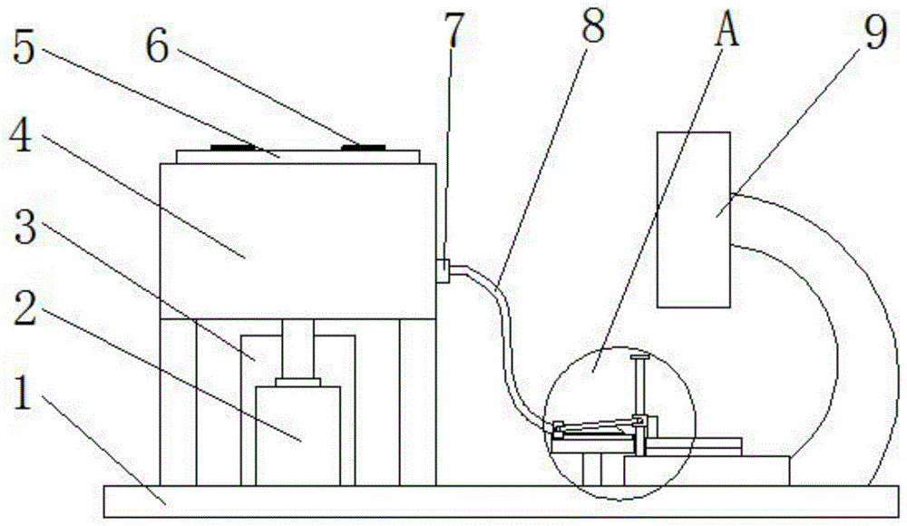
Nephrology department urine sediment integration microscopic examination device
Technical Field
The invention relates to the field of medical appliances, in particular to an integrated microscopic examination device for urinary sediments in nephrology department.
Background
Urine sediment (urinary sediment) examination is an examination of urine sediment by a microscope, and is used for identifying various pathological components such as cells, tubes, crystals, bacteria, parasites and the like in urine; the test method is an important routine test project for assisting diagnosis, positioning, identification and prognosis judgment of the urinary system diseases. Changes that cannot be detected in general trait tests or chemical tests can be detected by sedimentation tests, such as urine protein test negative and microscopic examination of small numbers of red blood cells. It is explained that the results of urine sedimentation must be judged by comprehensive analysis by referring to the results of physical and chemical examinations and combining clinical data.
With the popularization of urine analyzers in urine routine examination, part of inspectors neglect the importance of urinary sediment microscopic examination due to excessive dependence on the instruments, and particularly for urine samples with negative detection results of the urine analyzers, the urine samples are reported without error, the urinary sediment microscopic examination is not carried out, and the possible visible components such as casts, red and white cells, epithelial cells, crystals and the like are reported. Moreover, the test strip is often interfered by some chemicals such as drugs in urine, and false negative results appear. The urinary sediment microscopic examination can timely find partial error reports of the urine analyzer and timely correct the partial error reports. However, the conventional urinary sediment examination is complicated in operation and low in efficiency. There is a need for a device that can be operated in a centralized and integrated manner, that can improve work efficiency and ensure accuracy, and that reduces the workload of medical personnel.
Disclosure of Invention
1. Technical problem to be solved
The technical problem to be solved by the invention is to provide an integrated microscopic examination device for urinary sediment in nephrology department, which integrates the centrifugal treatment of the microscopic examination of the urinary sediment and the devices and instruments required by the microscopic examination, can be integrally operated in a centralized manner, is convenient for sampling and conveying the urinary sediment, is also convenient for collecting urine waste liquid, can improve the working efficiency and ensure the accuracy, and can also reduce the workload of medical staff.
2. Technical scheme
In order to solve the problems, the invention adopts the following technical scheme:
an integrated microscopic examination device for urinary sediments in nephrology department comprises a base, and a centrifugal mechanism and a microscopic detection mechanism which are respectively arranged on the base, wherein the microscopic detection mechanism comprises a microscope fixed on the base; the centrifugal mechanism comprises an outer fixed cylinder and a centrifugal turntable, the outer fixed cylinder is supported on the base through a support rod, the centrifugal turntable is rotatably arranged in the outer fixed cylinder, the upper end face of the outer fixed cylinder is arranged in an open manner, a motor fixed on the base is arranged below the outer fixed cylinder, an output shaft of the motor vertically penetrates upwards through the bottom of the outer fixed cylinder and is fixedly connected with the bottom of the centrifugal turntable, the outer side wall of the centrifugal turntable is completely attached to the inner wall of the outer fixed cylinder, and a gap is reserved between the bottom of the centrifugal turntable and the inner bottom of the outer fixed cylinder;
the centrifugal turntable is internally provided with at least one circularly distributed containing cavity for containing urine at equal intervals, each containing cavity comprises an upper containing cavity penetrating through the upper end surface of the centrifugal turntable, a middle containing cavity penetrating through the bottom of the upper containing cavity and a lower containing cavity penetrating through the bottom of the middle containing cavity, the width of the middle containing cavity is larger than the widths of the upper containing cavity and the lower containing cavity, the height of the upper containing cavity is larger than the height of the lower containing cavity, a plugging block for plugging the upper end port or the lower end port of the middle containing cavity is arranged in the middle containing cavity, the plugging block is formed by fixing two circular truncated cones symmetrically arranged about the horizontal central plane of the plugging block together, the diameter of the end surface of the plugging block is smaller than the diameter of the end port on the corresponding side of the middle containing cavity, the diameter of the middle of the plugging block is larger than the diameter of the upper end port and the lower end port of the middle containing cavity, and a lifting rod vertically penetrating through the bottom of the centrifugal turntable downwards is fixed at the center of the bottom of the plugging block, a liquid drainage channel communicated with the bottom of the lower cavity and penetrating through the outer side surface of the centrifugal turntable is formed in the centrifugal turntable on one side of the lower cavity;
the two sides of the outer fixed cylinder are respectively provided with a urinary sediment port and a waste liquid outlet which can be communicated with the liquid drainage channel, the side of the inner bottom of the outer fixed cylinder, corresponding to the urinary sediment port, is fixedly provided with a first electromagnet, and the bottom of the lifting rod is higher than the first electromagnet and is fixedly provided with a first permanent magnet which is in ferromagnetic repulsion with the first electromagnet; a vertically arranged top touch rod is arranged on the inner bottom of the outer fixing cylinder in a penetrating mode at the side corresponding to the waste liquid discharge port, the bottom of the top touch rod is located below the outer fixing cylinder and is fixedly provided with a limiting block, the width of the limiting block is larger than that of the top touch rod, a second permanent magnet is fixed on the limiting block, a second electromagnet located right above the second permanent magnet is fixed on the bottom surface of the outer fixing cylinder, the second permanent magnet and the second electromagnet are attracted in a magnetic mode, and a first spring connected to the bottom surface of the outer fixing cylinder is fixed on the upper end face of the limiting block; when the second electromagnet is electrified to adsorb the second permanent magnet, the blocking block is positioned in the middle of the middle containing cavity, and the upper port and the lower port of the middle containing cavity are both in an open state; the utility model discloses a urine sediment detection mechanism, including the urine sediment opening, the base is fixed with a collection waste liquid section of thick bamboo, the outer port department of urine sediment opening and waste liquid discharge port all is equipped with the union coupling head of fixing on the external fixation section of thick bamboo, the union coupling head outside that the urine sediment opening corresponds is connected with the censorship hose that accesss to microscopic detection mechanism, be fixed with a collection waste liquid section of thick bamboo on the base, the union coupling head outside that waste liquid discharge port corresponds is connected with the waste liquid discharge pipe that communicates with a collection waste liquid section of thick bamboo.
Furthermore, the top end of the centrifugal turntable is provided with a sealing cover for plugging an upper port of the upper cavity, and the sealing cover is provided with a sealing adhesive layer matched with the upper port of the upper cavity. The sealed lid covers the last port department that holds the chamber to seal this port through sealing glue layer, when centrifugal turntable rotated and carries out centrifugal treatment to the urine that holds the intracavity, can effectively prevent that the urine from splashing.
Furthermore, a sealing rubber ring is arranged at the position of the centrifugal turntable through which the lifting rod passes. The sealing rubber ring can prevent urinary sediment or urine supernatant from leaking from the position on the centrifugal turntable, through which the lifting rod passes, so that urine can be ensured to enter the liquid drainage channel.
Furthermore, a bearing sleeved on the output shaft is arranged at a position on the outer fixing cylinder, through which the output shaft of the power supply machine passes. The bearing can better restrict the output shaft of the motor to keep a vertical state, the rotation of the output shaft of the motor is not influenced, and the output shaft of the motor is better connected with the outer fixed cylinder in a rotating mode.
Furthermore, the lower end of the lifting rod is sleeved with a second spring fixed on the bottom surface of the centrifugal turntable. Under the action of magnetic repulsion of the first electromagnet to the first permanent magnet, the first permanent magnet can push the lifting rod to ascend, and the second spring is compressed until the blocking block blocks the upper end opening of the middle accommodating cavity; after first electro-magnet outage, first permanent magnet and lifter can reset to initial condition fast under the reset action of second spring, and at this moment, the lower port that holds the chamber in the middle of the better shutoff of shutoff piece.
Furthermore, the microscope comprises a microscope base fixed on the base, a fixing plate fixed on the microscope base and a lifting plate used for pressing the fixing plate, wherein a guide rod vertically fixed on the microscope base is arranged on one side of the lifting plate, and a second sliding block fixedly connected with the lifting plate is sleeved on the guide rod in a sliding manner; the micro-detection mechanism comprises a flow guide pipe connected to the output end of the delivery inspection hose, the flow guide pipe is transversely arranged, a small supporting platform fixed to the base is arranged below the flow guide pipe, a sliding rail is arranged on the upper end face of the small supporting platform, a first sliding block connected to the sliding rail in a sliding mode is fixed to one end, connected to the delivery inspection hose, of the flow guide pipe, a hinged plate is connected between the first sliding block and the second sliding block, the two ends of the hinged plate are hinged to sliding blocks on the corresponding sides respectively, and the second sliding block is higher than the first sliding block all the time. When the urinary sediment is detected, the first sliding block moves to the side where the microscope is located along the sliding rail to drive the flow guide pipe to move to the middle of the fixed plate; meanwhile, the first sliding block pushes the second sliding block to move upwards along the guide rod through the hinged plate, and the first sliding block can drive the lifting plate to move upwards, so that the glass slide and the cover glass can be conveniently mounted; treat that the urinary sediment gets into the honeycomb duct through the censorship hose to after along the honeycomb duct drippage on the slide, promote first slider and remove to microscope one side dorsad, drive the honeycomb duct and remove outside the fixed plate, simultaneously, first slider promotes the second slider through the articulated slab and moves down along the guide arm, and it can drive the lifter plate and move down, and to pressing on the fixed plate, make the cover glass press on the slide, later alright observe the urinary sediment through microscope.
Furthermore, the upper end face of the fixing plate is provided with an inward concave lower embedded groove used for clamping a glass slide, the lower end face of the lifting plate is provided with an inward concave upper embedded groove used for clamping a cover glass, and the upper part of the lifting plate is provided with a notch communicated with the upper embedded groove. Can comparatively stable installation slide glass through inlay the groove down, can comparatively stable installation glass lid through last inlay groove, can be convenient for observe the urine sediment of centre gripping between slide glass and glass lid through the breach.
3. Advantageous effects
(1) The centrifugal mechanism is provided with a centrifugal turntable with an accommodating cavity, the accommodating cavity comprises an upper accommodating cavity, a middle accommodating cavity and a lower accommodating cavity which are sequentially communicated, the width of the middle accommodating cavity is larger than that of the upper accommodating cavity and the lower accommodating cavity, a blocking block is arranged in the middle accommodating cavity, the bottom of the blocking block is connected with a lifting rod, the lower port of the middle accommodating cavity is blocked by the blocking block in an initial state, urine to be detected is poured into the accommodating cavity, the urine cannot enter the lower accommodating cavity, after the centrifugal turntable is driven by a motor to rotate, the urine can be layered, supernatant is completely positioned in the upper accommodating cavity, urine sediments are mostly positioned in the middle accommodating cavity and are partially positioned at the lower end of the upper accommodating cavity, at the moment, the upper port of the middle accommodating cavity can be blocked by pushing the lifting rod to move upwards, the lower port of the middle accommodating cavity is opened, the urine sediments in the middle accommodating cavity can enter the lower accommodating cavity, and the urine sediments are effectively separated, the urinary sediment can be conveniently sampled and detected; still attached formula outside centrifugal turntable is equipped with outer fixed cylinder, and has seted up the urinary sediment opening on the outer fixed cylinder, bottom one side in lower appearance chamber is equipped with the flowing back passageway that can communicate with the urinary sediment opening, the urinary sediment opening outside is connected with the delivery inspection hose that leads to microscopic detection mechanism, make the urinary sediment that holds the intracavity down can loop through the flowing back passageway, the urinary sediment opening and the delivery inspection hose deliver to microscopic detection mechanism and detect, the great error appears in the testing result that the urinary sediment that has avoided detecting and urine secondary mix and lead to.
(2) According to the invention, the first electromagnet is fixed on the side of the inner bottom of the outer fixed cylinder, which corresponds to the urinary sediment through hole, the bottom of the lifting rod is higher than the first electromagnet, and the first permanent magnet which is in ferromagnetic repulsion with the first electromagnet is fixed on the bottom of the lifting rod, when the liquid discharge channel of the corresponding cavity is communicated with the urinary sediment through hole, the first electromagnet is electrified, and the magnetic repulsion force on the first permanent magnet right above the first electromagnet is generated through the first electromagnet, so that the corresponding lifting rod and the blocking block can be moved upwards, the upper end hole of the middle cavity is blocked by the blocking block, and the blocking block is moved only in the urinary sediment, so that the supernatant of the urine and the urinary sediment can be prevented from being stirred; and the lower port of the middle containing cavity is opened, the urinary sediment in the middle containing cavity enters the lower containing cavity and then sequentially enters the corresponding liquid discharge channel, the urinary sediment port and the inspection hose, so that after the urine is centrifugally layered, the urinary sediment can be sampled and guided to the microscopic detection mechanism by electrifying the first electromagnet, and the urine detection device is simple to operate and convenient to apply.
(3) The invention is provided with a waste liquid collecting cylinder, one side of an outer fixed cylinder is provided with a waste liquid discharge port, the outer side of the outer fixed cylinder is connected with a waste liquid discharge pipe communicated with the waste liquid collecting cylinder, the side of the inner bottom of the outer fixed cylinder corresponding to the waste liquid discharge port is provided with a vertically arranged top touch rod in a penetrating way, the bottom of the top touch rod is fixed with a limiting block, a second permanent magnet is fixed on the limiting block, the bottom surface of the outer fixed cylinder is fixed with a second electromagnet opposite to the second permanent magnet, the second permanent magnet and the second electromagnet are attracted, when a liquid discharge channel of a corresponding cavity is communicated with the waste liquid discharge port, each second electromagnet is electrified and can adsorb the second permanent magnet to drive the limiting block and the top touch rod to ascend, the top touch rod pushes the first permanent magnet and the lifting rod to ascend until a blocking block is positioned in the middle part of the middle cavity, the upper and lower ports of the middle cavity are both in an open state, and residual urine sediment and supernatant in the cavity can enter the liquid discharge channel, and then the urine waste liquid is collected by sequentially passing through the waste liquid discharge port and the waste liquid discharge pipe to enter the waste liquid collecting cylinder, and the collection of the urine waste liquid can be achieved only by electrifying the second electromagnet, so that the control is simple and the application is convenient.
In conclusion, the device integrates the devices and instruments required by the centrifugal treatment and the microscopic examination of the urinary sediment microscopic examination, can be integrally operated in a centralized manner, is convenient for sampling and conveying the urinary sediment and collecting the urine waste liquid, can improve the working efficiency and ensure the accuracy, and can also reduce the workload of medical staff.
Drawings
FIG. 1 is a front view of the present invention in a schematic configuration;
FIG. 2 is an enlarged view of the area A in FIG. 2;
FIG. 3 is a schematic cross-sectional view of the fixing plate 18 and the lifting plate 17;
FIG. 4 is a schematic top view of a centrifuge mechanism;
FIG. 5 is a schematic structural view of the outer fixed cylinder 4 and the centrifugal rotor 5 on the section A-A in FIG. 3;
fig. 6 is a structural schematic diagram of the section B-B of the outer fixed cylinder 4 and the centrifugal rotor 5 in fig. 3.
Reference numerals: 1. a base; 2. a motor; 3. a waste liquid collecting cylinder; 4. an outer fixed cylinder; 5. a centrifugal turntable; 6. a sealing cover; 7. a pipe connector; 8. a delivery inspection hose; 9. a microscope; 10. a small support table; 11. a slide rail; 12. a first slider; 13. a flow guide pipe; 14. a hinge plate; 15. a guide bar; 16. a second slider; 17. a lifting plate; 18. a fixing plate; 19. a microscope base; 20. a liquid discharge channel; 21. a waste liquid discharge port; 22. a waste liquid discharge pipe; 23. opening urinary sediment; 24. a first permanent magnet; 25. sealing the rubber ring; 26. a lower cavity; 27. a middle holding cavity; 28. an upper cavity; 29. sealing the adhesive layer; 30. a plugging block; 31. a lifting rod; 32. a first electromagnet; 33. a bearing; 34. a notch; 35. an upper embedding groove; 36. a lower embedding groove; 37. a top feeler lever; 38. a second electromagnet; 39. a second permanent magnet; 40. a first spring; 41. a limiting block; 42. a second spring.
Detailed Description
The present invention will be described in further detail with reference to the accompanying drawings and examples.
Examples
The integrated microscopic examination device for the urinary sediment in the nephrology department as shown in figure 1 comprises a base 1, and a centrifugal mechanism and a microscopic detection mechanism which are respectively arranged on the base 1, wherein the microscopic detection mechanism comprises a microscope 9 fixed on the base 1; the centrifugal mechanism comprises an outer fixed cylinder 4 supported on the base 1 through a support rod and a centrifugal turntable 5 rotatably arranged in the outer fixed cylinder 4, the upper end face of the outer fixed cylinder 4 is arranged in an open manner, a motor 2 fixed on the base 1 is arranged below the outer fixed cylinder 4, as shown in fig. 5 and 6, an output shaft of the motor 2 vertically penetrates upwards through the bottom of the outer fixed cylinder 4 and is fixedly connected with the bottom of the centrifugal turntable 5, the outer side wall of the centrifugal turntable 5 is completely attached to the inner wall of the outer fixed cylinder 4, and a gap is reserved between the bottom of the centrifugal turntable 5 and the inner bottom of the outer fixed cylinder 4;
as shown in fig. 5, 6 and 4, at least one circularly distributed containing cavity (four cavities are shown in fig. 3) for containing urine is provided in the centrifugal turntable 5 at equal intervals, each containing cavity includes an upper containing cavity 28 penetrating through the upper end surface of the centrifugal turntable 5, a middle containing cavity 27 penetrating through the bottom of the upper containing cavity 28, and a lower containing cavity 26 penetrating through the bottom of the middle containing cavity 27, the width of the middle containing cavity 27 is greater than the width of the upper containing cavity 28 and the lower containing cavity 26, the height of the upper containing cavity 28 is greater than the height of the lower containing cavity 26, a blocking block 30 for blocking the upper port or the lower port of the middle containing cavity 27 is provided in the middle containing cavity 27, the blocking block 30 is formed by fixing two truncated cones symmetrically arranged about the horizontal center surface of the blocking block 30, the end surface diameter of the blocking block 30 is smaller than the port diameter of the corresponding side of the middle containing cavity 27, the middle diameter of the blocking block 30 is greater than the diameters of the upper and lower ports of the middle containing cavity 27, a lifting rod 31 vertically penetrating through the bottom of the centrifugal turntable 5 downwards is fixed at the center of the bottom of the blocking block 30, and a liquid drainage channel 20 communicated with the bottom of the lower cavity 26 and penetrating through the outer side surface of the centrifugal turntable 5 is formed in the centrifugal turntable 5 on one side of the lower cavity 26;
as shown in fig. 4, a urinary sediment through hole 23 and a waste liquid outlet 21 which can be communicated with the liquid drainage channel 20 are respectively arranged on two sides of the outer fixed cylinder 4, as shown in fig. 5, a first electromagnet 32 is fixed on the side of the inner bottom of the outer fixed cylinder 4 corresponding to the urinary sediment through hole 23, the bottom of the lifting rod 31 is higher than the first electromagnet 32 and is fixed with a first permanent magnet 24 which is magnetically repelled with the first electromagnet 32; as shown in fig. 6, a vertically arranged top touch rod 37 is penetrated through the side of the inner bottom of the outer fixed cylinder 4 corresponding to the waste liquid discharge port 21, the bottom of the top touch rod 37 is positioned below the outer fixed cylinder 4 and is fixed with a limit block 41 with a width larger than that of the top touch rod 37, a second permanent magnet 39 is fixed on the limit block 41, a second electromagnet 38 positioned right above the second permanent magnet 39 is fixed on the bottom surface of the outer fixed cylinder 4, the second permanent magnet 39 and the second electromagnet 38 are magnetically attracted, and a first spring 40 connected to the bottom surface of the outer fixed cylinder 4 is fixed on the upper end surface of the limit block 41; after the second electromagnet 38 is electrified to adsorb the second permanent magnet 39, the blocking block 30 is located in the middle of the middle accommodating cavity 27, and the upper and lower ports of the middle accommodating cavity 27 are both in an open state; as shown in fig. 1 and 4, the external ports of the urinary sediment port 23 and the waste liquid discharge port 21 are respectively provided with a pipe connector 7 fixed on the external fixing cylinder 4, the outside of the pipe connector 7 corresponding to the urinary sediment port 23 is connected with a delivery detection hose 8 leading to a microscopic detection mechanism, the base 1 is fixed with a waste liquid collecting cylinder 3, and the outside of the pipe connector 7 corresponding to the waste liquid discharge port 21 is connected with a waste liquid discharge pipe 22 communicated with the waste liquid collecting cylinder 3.
In this embodiment, as shown in fig. 1 and 4, a sealing cover 6 for sealing an upper port of the upper cavity 28 is disposed at a top end of the centrifugal turntable 5, as shown in fig. 5, and a sealing adhesive layer 29 adapted to the upper port of the upper cavity 28 is disposed on the sealing cover 6. The sealing cover 6 covers the upper port of the upper cavity 28 and seals the upper port through the sealing glue layer 29, so that the urine can be effectively prevented from splashing when the centrifugal turntable 5 rotates to carry out centrifugal treatment on the urine in the cavity.
In this embodiment, as shown in fig. 5, a sealing rubber ring 25 is provided on the centrifugal rotor 5 at a position through which the lifting rod 31 passes. The sealing rubber ring 25 can prevent urine sediment or urine supernatant from leaking from the position on the centrifugal turntable 5 through which the lifting rod 31 passes, thereby ensuring that urine enters the liquid discharge channel 20.
In the present embodiment, as shown in fig. 5, a bearing 33 fitted around the output shaft of the power supply 2 is provided at a position of the outer fixed cylinder 4 through which the output shaft passes. The bearing 33 can better limit the output shaft of the motor 2 to keep a vertical state, does not influence the rotation of the output shaft of the motor 2, and better realizes the rotation connection of the output shaft of the motor 2 and the outer fixed cylinder 4.
In this embodiment, as shown in fig. 5 and 6, the lower end of the lifting rod 31 is sleeved with a second spring 42 fixed on the bottom surface of the centrifugal turntable 5. Under the action of the magnetic repulsion of the first electromagnet 32 to the first permanent magnet 24, the first permanent magnet 24 can push the lifting rod 31 to ascend, and the second spring 42 is compressed until the blocking block 30 blocks the upper end opening of the middle accommodating cavity 27; after the first electromagnet 32 is powered off, the first permanent magnet 24 and the lifting rod 31 can be quickly reset to the initial state under the reset action of the second spring 42, and at this time, the blocking block 30 better blocks the lower port of the intermediate cavity 27.
In this embodiment, as shown in fig. 2, the microscope 9 includes a microscope base 19 fixed on the base 1, a fixing plate 18 fixed on the microscope base 19, and a lifting plate 17 for pressing on the fixing plate 18, one side of the lifting plate 17 is provided with a guide rod 15 vertically fixed on the microscope base 19, and the guide rod 15 is slidably sleeved with a second slider 16 fixedly connected with the lifting plate 17; the microscopic detection mechanism comprises a guide pipe 13 connected to the output end of the censorship hose 8, the guide pipe 13 is transversely arranged, a small support table 10 fixed on the base 1 is arranged below the guide pipe 13, a slide rail 11 is arranged on the upper end face of the small support table 10, a first slide block 12 connected to the base 1 in a sliding mode is fixed at one end, connected to the censorship hose 8, of the guide pipe 13, a hinged plate 14 is connected between the first slide block 12 and a second slide block 16, two ends of the hinged plate 14 are hinged to slide blocks on the corresponding sides respectively, and the second slide block 16 is higher than the first slide block 12 all the time. When detecting urinary sediment, the first slide block 12 moves to the side of the microscope 9 along the slide rail 11 to drive the flow guide pipe 13 to move to the middle of the fixed plate 18; meanwhile, the first slide block 12 pushes the second slide block 16 to move upwards along the guide rod 15 through the hinged plate 14, and the second slide block can drive the lifting plate 17 to move upwards, so that the glass slide and the cover glass can be conveniently loaded; after the urinary sediment enters the flow guide tube 13 through the inspection delivery hose 8 and drops on the glass slide along the flow guide tube 13, the first sliding block 12 is pushed to move towards one side back to the microscope 9 to drive the flow guide tube 13 to move out of the fixed plate 18, meanwhile, the first sliding block 12 pushes the second sliding block 16 to move downwards along the guide rod 15 through the hinged plate 14, the second sliding block can drive the lifting plate 17 to move downwards until the lifting plate presses on the fixed plate 18, so that the glass slide is pressed on the glass slide, and then the urinary sediment can be observed through the microscope 9.
In the present embodiment, as shown in fig. 3, the upper end surface of the fixing plate 18 is provided with a concave lower insertion groove 36 for clamping a slide, the lower end surface of the lifting plate 17 is provided with a concave upper insertion groove 35 for clamping a cover glass, and the upper portion of the lifting plate 17 is provided with a notch 34 communicating with the upper insertion groove 35. The glass slide can be stably installed through the lower embedded groove 36, the cover glass can be stably installed through the upper embedded groove 35, and the urinary sediment clamped between the glass slide and the cover glass can be conveniently observed through the notch 34.
The specific application process of the integrated microscopic examination device for the urinary sediment in the nephrology department is as follows:
in the initial state, the blocking block 30 is located at a lower position and blocks the lower port of the intermediate cavity 27; when urine is to be detected, the sealing cover 6 is firstly opened, the urine to be detected is guided into the containing cavity, because the lower port of the middle containing cavity 27 is sealed, the urine only remains in the upper containing cavity 28 and the middle containing cavity 27, then the motor 2 is started to drive the centrifugal turntable 5 to rotate, the centrifugal treatment of the urine in the containing cavity can be realized, after the motor 2 stops rotating, the urine generates layering phenomenon, supernatant is totally positioned in the upper containing cavity 28, most of urine sediments are positioned in the middle containing cavity 27 and are partially positioned at the lower end of the upper containing cavity 28, then the flow guide pipe 13 is moved to a position between the fixed plate 18 and the lifting plate 17, the glass slide and the cover glass are mounted, then the centrifugal turntable 5 is rotated, the containing cavity with the urine is rotated to the side of the urine sediment port 23, the corresponding liquid drainage channel 20 is communicated with the urine sediment port 23, the first electromagnet 32 is electrified, and the first electromagnet 32 generates magnetic repulsion force to the first permanent magnet 24 right above the first electromagnet, the corresponding lifting rod 31 and the blocking block 30 are pushed to move upwards until the blocking block 30 blocks the upper end opening of the middle containing cavity 27, and the movement of the blocking block 30 is only carried out in the urine sediments, so that the supernatant liquid and the urine sediments of the urine can be prevented from being stirred; when the upper port of the intermediate cavity 27 is plugged by the plugging block 30, the lower port of the intermediate cavity 27 is opened, the urinary sediment in the intermediate cavity 27 enters the lower cavity 26 and sequentially enters the corresponding liquid discharge channel 20 and the urinary sediment port 23, finally drops on the glass slide through the inspection delivery hose 8 and the flow guide pipe 13, and the amount of the taken urinary sediment can be controlled by arranging a switch valve on the flow guide pipe 13 or the inspection delivery hose 8; at this moment, the first slide block 12 is moved in the reverse direction to drive the flow guide pipe 13 to reset, and simultaneously, the first slide block 12 drives the second slide block 16 to descend through the hinged plate 14, so that the lifting plate 17 can be driven to descend to be pressed on the fixing plate 18, the cover glass is pressed on the glass slide, and finally, the urinary sediment is observed from the notch 34 through the microscope 9.
After the detection is finished, the centrifugal turntable 5 is rotated until the containing cavity moves to the side of the waste liquid outlet 21, and the corresponding liquid discharge channel 20 is communicated with the waste liquid outlet 21, in the process, because the outer peripheral side of the centrifugal turntable 5 is completely attached to the inner peripheral side of the outer fixed cylinder 4, the residual urine sediments in the liquid discharge channel 20 and the lower containing cavity 26 cannot flow out accidentally; then the second electromagnet 38 is electrified, the second electromagnet 38 adsorbs a second permanent magnet 39 to drive a limiting block 41 and a top contact rod 37 to move upwards, a first spring 40 is compressed, the top contact rod 37 pushes the first permanent magnet 24 and a lifting rod 31 to ascend until a blocking block 30 is positioned in the middle of a middle containing cavity 27, at the moment, the upper port and the lower port of the middle containing cavity 27 are both in an open state, residual urine sediments and supernatant in the containing cavity can enter a liquid drainage channel 20 and then enter a waste liquid collecting cylinder 3 through a waste liquid discharge port 21 and a waste liquid discharge pipe 22 in sequence, and collection of urine waste liquid is achieved; the second slide block 16 is directly pushed to move upwards, so that the glass slide and the cover glass can be conveniently detached; the inspection hose 8 and the waste liquid discharge pipe 22 can be detached from the outer fixed cylinder 4 through the pipe joint 7, thereby facilitating cleaning or replacement of the respective parts.
According to the invention, the device and the apparatus required by the centrifugal treatment and the microscopic examination of the urinary sediment microscopic examination are integrated, the integrated operation can be centralized, the sampling and the conveying of the urinary sediment are convenient, the collection of the urine waste liquid is convenient, the working efficiency is improved, the accuracy is ensured, and the workload of medical staff is reduced.
It should be understood by those skilled in the art that the above embodiments are only for illustrating the present invention and are not to be used as a limitation of the present invention, and that changes and modifications to the above embodiments may fall within the scope of the appended claims within the spirit of the present invention.