Method and device for transition of space trajectories of adjacent joints
Technical Field
The invention relates to the field of robot motion control, in particular to a method and a device for transition of space trajectories of adjacent joints.
Background
The motion space of the mechanical arm is divided into a joint space and a Cartesian space, and the motion of the current industrial mechanical arm in the independent joint space and the Cartesian space is very easy to realize. The main method for transition of the mixed space of the joint space and the Cartesian space is to convert the joint space into the Cartesian space through forward kinematics, and then perform trajectory transition on instructions of the Cartesian space and the Cartesian space, for example, perform processing of reducing the speed to zero at an intersection point. For joint space planning of a general robot, namely PTP, each joint usually plans motion independently from a starting point position to a termination point position, and each joint can be started at the same time and can reach a specified point position. The simple joint movement has low requirements on the control of the movement process, and is suitable for the operation with the requirement of quick positioning. However, for the continuous joint space planning movement, if the joints move independently, the speed of each joint is accelerated from a movement starting point to a middle point and finally to a target point, then to 0, and in the continuous start-stop movement, each joint needs to be started and stopped once when each middle point occurs. Therefore, the movement process is uncontrollable, all joints cannot be synchronized to the middle point position, the function of avoiding fixed point obstacles cannot be realized, the efficiency is greatly reduced, the time cost and the energy consumption cost are increased, and the requirements of actual operation are not met.
Disclosure of Invention
The invention aims to solve the technical problem that the time cost and the energy consumption cost of the adjacent joint space track transition method in the prior art are high.
The invention solves the technical problems through the following technical means: a method of adjacent joint space trajectory transition, the method comprising:
the method comprises the following steps: time synchronization is carried out on each shaft in adjacent space, so that multi-shaft synchronization time reaches each position;
step two: taking the final speed of the track of the current section as the initial speed of the track of the next section, taking the initial speed of the track of the current section as the final speed of the track of the previous section, and planning the track to enable the speeds of adjacent spaces to be in smooth transition; for continuous multi-section joint space track transition, judging the displacement of the current joint space and the next joint space, and taking the minimum value of the running speeds of two adjacent joint space motion sections as the current joint end speed when the displacement directions are the same and the displacement of the current joint space is larger than that of the next joint space; if the displacement of the current joint space is smaller than that of the next joint space, the maximum value of the running speeds of the motion sections of the adjacent two joint spaces is taken as the current joint end speed by the current joint space joint end speed;
step three: performing interpolation operation according to output data of the track plan so as to make the track continuous; wherein the output data includes an initial velocity, a final velocity, and a position.
The invention makes the multi-axis synchronous time reach each accurate position by time synchronization of each axis in the adjacent space, avoids the occurrence of continuous start-stop motion of each axis from the motion starting point, to the middle point, and finally to the target point, the speed is accelerated from 0, then to 0, and meanwhile, the final speed of the track of the current section is taken as the initial speed of the track of the next section, the initial speed of the track of the current section is taken as the final speed of the track of the previous section, the speed of each axis is smoothly connected and transited at the intersection point of the motion of the two sections of tracks, the speed is smooth at each middle process point, the unnecessary start-stop is reduced, and the time cost and the energy consumption cost are reduced.
Preferably, the first step includes: and each axis firstly calculates the single PTP running time of each axis according to the input information and the parameter self-adaptive S-speed planning, then takes the maximum running time in each axis as the reference time, and performs the S-speed planning based on the reference time on other axes, thereby realizing the time synchronization of each axis of the single PTP.
Preferably, the second step includes: for a single PTP, the track planning can be completed by setting the initial speed and the final speed of the single PTP, and for continuous PTP of multiple sections, the final speed of the PTP of the current section and the initial speed of the PTP of the next section are in smooth transition.
Preferably, the second step further comprises: for consecutive multi-segment PTPs, smoothly transitioning the last speed of the current segment PTP to the initial speed of the next segment PTP comprises: judging the displacement deta _ x1 of the PTP of the current segment and the displacement deta _ x2 of the PTP of the next segment;
under the condition that the directions of the displacement deta _ x1 of the current segment PTP and the displacement deta _ x2 of the next segment PTP are the same, when the deta _ x1> -deta _ x2, the minimum value of the running speeds of two adjacent PTP moving segments is taken as the current joint end speed by the current PTP joint end speed; if the deta _ x1 is less than the deta _ x2, the current PTP joint end speed takes the maximum value of the running speeds of two adjacent PTP moving sections as the current joint end speed;
under the condition that the directions of the displacement deta _ x1 of the current PTP segment and the displacement deta _ x2 of the next PTP segment are opposite, the final speed of the current joint is directly set to be 0, then the final speed of the current PTP segment is used as the initial speed of the next PTP segment, and the smooth transition of the speeds is completed.
The invention also provides a device for spatial trajectory transition of adjacent joints, which comprises:
the time synchronization module is used for carrying out time synchronization on each shaft in adjacent space so that multi-shaft synchronization time reaches each position;
the track planning module is used for planning the track by taking the final speed of the current section of track as the initial speed of the next section of track and taking the initial speed of the current section of track as the final speed of the previous section of track so as to enable the adjacent space speeds to be in smooth transition; for continuous multi-section joint space track transition, judging the displacement of the current joint space and the next joint space, and taking the minimum value of the running speeds of two adjacent joint space motion sections as the current joint end speed when the displacement directions are the same and the displacement of the current joint space is larger than that of the next joint space; if the displacement of the current joint space is smaller than that of the next joint space, the maximum value of the running speeds of the motion sections of the adjacent two joint spaces is taken as the current joint end speed by the current joint space joint end speed;
the interpolation operation module is used for carrying out interpolation operation according to the output data of the track planning so as to ensure that the track is continuous; wherein the output data includes an initial velocity, a final velocity, and a position.
Preferably, the time synchronization module is further configured to: each axis firstly calculates the single PTP running time of each axis according to input information and parameter self-adaptive S-speed planning, then takes the maximum running time in each axis as reference time, and performs S-speed planning based on the reference time on other axes, thereby realizing the time synchronization of each axis of the single PTP.
Preferably, the trajectory planning module is further configured to: for a single PTP, the track planning can be completed by setting the initial speed and the final speed of the single PTP, and for continuous multi-section PTP, the final speed of the PTP of the current section and the initial speed of the PTP of the next section are in smooth transition;
preferably, the trajectory planning module is further configured to: for consecutive multi-segment PTPs, smoothly transitioning the last speed of the current segment PTP to the initial speed of the next segment PTP comprises: judging the displacement deta _ x1 of the PTP of the current segment and the displacement deta _ x2 of the PTP of the next segment;
under the condition that the directions of the displacement deta _ x1 of the current segment PTP and the displacement deta _ x2 of the next segment PTP are the same, when the deta _ x1> -deta _ x2, the minimum value of the running speeds of two adjacent PTP moving segments is taken as the current joint end speed by the current PTP joint end speed; if the deta _ x1 is less than the deta _ x2, the current PTP joint end speed takes the maximum value of the running speeds of two adjacent PTP moving sections as the current joint end speed;
under the condition that the directions of the displacement deta _ x1 of the current PTP segment and the displacement deta _ x2 of the next PTP segment are opposite, the final speed of the current joint is directly set to be 0, then the final speed of the current PTP segment is used as the initial speed of the next PTP segment, and the smooth transition of the speeds is completed.
The invention has the advantages that: the invention makes the multi-axis synchronous time reach each accurate position by time synchronization of each axis in the adjacent space, avoids the occurrence of continuous start-stop motion of each axis from the motion starting point, to the middle point, and finally to the target point, the speed is accelerated from 0, then to 0, and meanwhile, the final speed of the track of the current section is taken as the initial speed of the track of the next section, the initial speed of the track of the current section is taken as the final speed of the track of the previous section, the speed of each axis is smoothly connected and transited at the intersection point of the motion of the two sections of tracks, the speed is smooth at each middle process point, the unnecessary start-stop is reduced, and the time cost and the energy consumption cost are reduced.
Drawings
FIG. 1 is a flowchart of a method for spatial trajectory transition between adjacent joints according to an embodiment of the present invention;
FIG. 2 is a flowchart of an algorithm in a spatial trajectory transition method for adjacent joints according to an embodiment of the present invention;
FIG. 3 is a schematic diagram of joint space transition in a method for transition between adjacent joint space trajectories according to an embodiment of the present invention;
Detailed Description
In order to make the objects, technical solutions and advantages of the embodiments of the present invention clearer, the technical solutions in the embodiments of the present invention will be clearly and completely described below with reference to the embodiments of the present invention, and it is obvious that the described embodiments are some embodiments of the present invention, but not all embodiments. All other embodiments, which can be derived by a person skilled in the art from the embodiments given herein without making any creative effort, shall fall within the protection scope of the present invention.
Example 1
As shown in fig. 1, in the method for spatial trajectory transition of adjacent joints, the transition of spatial trajectories of adjacent joints mainly takes the final velocity of the previous joint instruction as the initial velocity of the next joint spatial instruction, and each motion axis of each joint spatial instruction is synchronized in time. The method comprises the following steps:
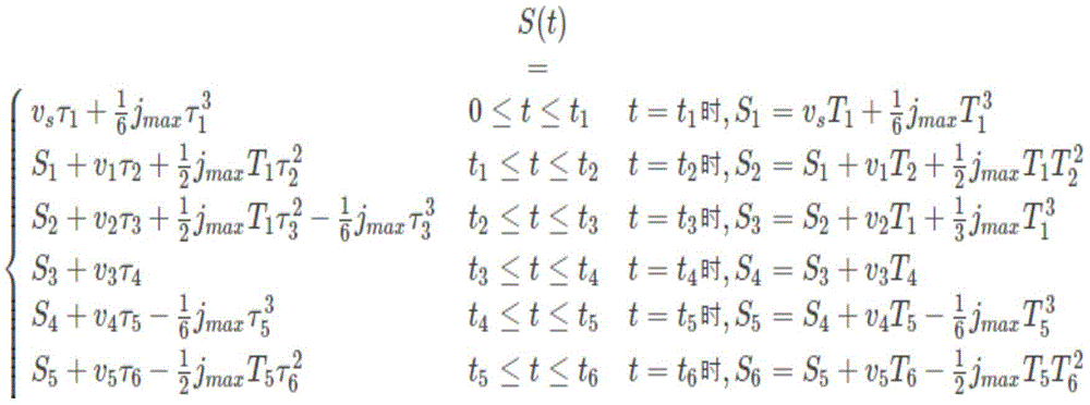
step S1: and carrying out time synchronization on the axes in adjacent space, so that the multi-axis synchronous time reaches each position. Each axis firstly calculates the single PTP running time of each axis according to input information and parameter self-adaptive S-speed planning, then takes the maximum running time in each axis as reference time, and performs S-speed planning based on the reference time on other axes to realize the time synchronization of each axis of the single PTP; the parameter self-adaptive S speed planning belongs to the prior art, and the main process comprises the steps of firstly solving the angular displacement S of each axis according to the position input by a user through an inverse kinematics relation, wherein J is jerk, a is acceleration and v is speed; the total time under corresponding displacement, velocity and acceleration can be obtained by the following formula
tk(k ═ 0, 1,. 7): representing the transition point moments of the various phases;
Tk(k ═ 0, 1,. 7): local time coordinate representing a time representation with the start point of each stage as a time zero
Tk=tk-tk-1(k=0,1,...7):
Tk(k ═ 1.. 7): the duration of the various phases.
Step S2: taking the final speed of the track of the current section as the initial speed of the track of the next section, taking the initial speed of the track of the current section as the final speed of the track of the previous section, and planning the track to enable the speeds of adjacent spaces to be in smooth transition; for continuous multi-section joint space track transition, judging the displacement of the current joint space and the next joint space, and taking the minimum value of the running speeds of two adjacent joint space motion sections as the current joint end speed when the displacement directions are the same and the displacement of the current joint space is larger than that of the next joint space; and if the displacement of the current joint space is smaller than that of the next joint space, taking the maximum value of the running speeds of the motion sections of the two adjacent joint spaces as the current joint end speed. For a single PTP, the track planning can be completed by setting the initial speed and the final speed of the single PTP, and for continuous multi-section PTP, the final speed of the PTP of the current section and the initial speed of the PTP of the next section are in smooth transition; this part belongs to the preplanning movement, and the advantage of this is that the preplanning movement part can plan all the information of a single PTP in a very short time. Meanwhile, the system can judge whether the data set by the user is reasonable according to the information, and the user is returned with prompt for modifying input information if the data set by the user is not reasonable, so that unpredictable risks existing in direct movement and the problem that the data of failure reasons cannot be obtained due to path planning failure are avoided.
Step S3: performing interpolation operation according to output data of the track plan so as to make the track continuous; wherein the output data includes an initial velocity, a final velocity, and a position. The specific process is as follows: interpolation is performed based on the output data to continue the trajectory. The interpolation motion is directly carried out according to the previous part of successfully preplanned data, the method has the advantages that the user data does not need to be processed again during the interpolation motion, the time is greatly saved, and meanwhile, the planning principle is consistent with the interpolation principle, so that the successfully planned data and the interpolation motion can be reached certainly. It should be noted that the preplanning is only to plan the initial speed and the final speed, and there is no point between the initial point and the end point, so that the interpolation operation is performed to make the trajectory continuous, and the interpolation operation belongs to the existing algorithm, which is not described herein again.
As shown in fig. 2 and 3, before the parameter adaptive S-speed planning, each input teaching point is extracted to a joint position array, and the last element of the position array is assigned to 0, so that the operation requirement is meaningless; extracting the operation speed specified by each teaching instruction to a speed array, and assigning the last element of the speed array to be 0, so that the operation requirement is meaningless; extracting the maximum acceleration and the jerk set by each section; the velocity at the end point of each section is initially set to be a small value of the velocity values of two adjacent ends; calculating parameter type marks according to the starting position and the end position of each section and the positive and negative of the positions, performing translation and symmetric pre-transformation, and converting the marks into a starting position of 0 and an end position of a positive number; after the pre-transformation of the velocity planning parameters of each joint, the following process can be summarized as performing S-velocity planning based on the designated velocity on each joint to obtain the time consumed by each axis. Taking the joint which consumes the longest time as a reference axis, and taking the longest time as reference time; the reference axis interpolation type is S speed planning based on designated speed, and the other axis interpolation types are S speed planning based on designated time. Pre-planning the speed of each axis; and obtaining the final speed of the section after the S-speed plan is corrected, and taking the final speed as the initial speed of the next section. And each joint carries out corresponding interpolation according to the interpolation type. And performing parameter regression transformation according to the parameter type mark to obtain interpolated position, velocity and acceleration information.
For a single segment PTP, only the initial speed and the final speed need to be set. However, when the PTP in the consecutive segments are at the same speed, the last speed of the PTP in the current segment is smoothly transited to the initial speed of the PTP in the next segment, i.e. the speed is the same as the direction. According to the speed plan, the final speed of each segment of PTP needs to be input. For the continuous multi-segment PTP, judging the displacement deta _ x1 of the current segment PTP and the displacement deta _ x2 of the next segment PTP, if the displacement directions are the same, when the deta _ x1> is deta _ x2, the current PTP joint end speed takes the minimum value of the running speeds of two adjacent PTP moving segments as the current joint end speed; if the deta _ x1 is less than the deta _ x2, the current PTP joint end speed takes the maximum value of the running speeds of two adjacent PTP moving segments as the current joint end speed; and if the displacement is reversed, directly setting the final speed of the current joint to be 0, and then taking the final speed of the PTP of the current section as the initial speed of the PTP of the next section to finish the smooth transition of the speed. If multi-segment PTP continuity exists, only the final joint speed and the initial joint speed of two adjacent segments need to be calculated, and the method is irrelevant to other PTP segments and data. When 0 appears in the deta _ x1 or the deta _ x2, namely some joints do not move, but the expected joints have initial and final speeds, and other joints normally rotate, the situation is compatible, the displacement magnitude is directly compared, corresponding processing is carried out, and whether the displacement directions are the same or not does not need to be distinguished.
Through the technical scheme, the invention provides a method for transition of space trajectories of adjacent joints, which is characterized in that time synchronization is carried out on each shaft in adjacent space, so that multi-shaft synchronization time reaches each accurate position, the situation that each shaft accelerates from 0 to 0 and then accelerates to 0 from an initial motion point to a middle point and finally to a target point is avoided, and at 0, the continuous start-stop motion is carried out.
Example 2
Corresponding to embodiment 1 of the present invention, embodiment 2 of the present invention further provides an adjacent joint space trajectory transition device, including:
the time synchronization module is used for carrying out time synchronization on each shaft in adjacent space so that multi-shaft synchronization time reaches each position;
the track planning module is used for planning the track by taking the final speed of the current section of track as the initial speed of the next section of track and taking the initial speed of the current section of track as the final speed of the previous section of track so as to enable the adjacent space speeds to be in smooth transition; for continuous multi-section joint space track transition, judging the displacement of the current joint space and the next joint space, and taking the minimum value of the running speeds of two adjacent joint space motion sections as the current joint end speed when the displacement directions are the same and the displacement of the current joint space is larger than that of the next joint space; if the displacement of the current joint space is smaller than that of the next joint space, the maximum value of the running speeds of the motion sections of the adjacent two joint spaces is taken as the current joint end speed by the current joint space joint end speed;
the interpolation operation module is used for carrying out interpolation operation according to the output data of the track planning so as to ensure that the track is continuous; wherein the output data includes an initial velocity, a final velocity, and a position.
Specifically, the time synchronization module is further configured to: each axis firstly calculates the single PTP running time of each axis according to input information and parameter self-adaptive S-speed planning, then takes the maximum running time in each axis as reference time, and performs S-speed planning based on the reference time on other axes, thereby realizing the time synchronization of each axis of the single PTP.
Specifically, the trajectory planning module is further configured to: for a single PTP, the track planning can be completed by setting the initial speed and the final speed of the single PTP, and for continuous multi-section PTP, the final speed of the PTP of the current section and the initial speed of the PTP of the next section are in smooth transition;
specifically, the trajectory planning module is further configured to: for consecutive multi-segment PTPs, smoothly transitioning the last speed of the current segment PTP to the initial speed of the next segment PTP comprises: judging the displacement deta _ x1 of the PTP of the current segment and the displacement deta _ x2 of the PTP of the next segment;
under the condition that the directions of the displacement deta _ x1 of the current segment PTP and the displacement deta _ x2 of the next segment PTP are the same, when the deta _ x1> -deta _ x2, the minimum value of the running speeds of two adjacent PTP moving segments is taken as the current joint end speed by the current PTP joint end speed; if the deta _ x1 is less than the deta _ x2, the current PTP joint end speed takes the maximum value of the running speeds of two adjacent PTP moving sections as the current joint end speed;
under the condition that the directions of the displacement deta _ x1 of the current PTP segment and the displacement deta _ x2 of the next PTP segment are opposite, the final speed of the current joint is directly set to be 0, then the final speed of the current PTP segment is used as the initial speed of the next PTP segment, and the smooth transition of the speeds is completed.
The above examples are only intended to illustrate the technical solution of the present invention, but not to limit it; although the present invention has been described in detail with reference to the foregoing embodiments, it will be understood by those of ordinary skill in the art that: the technical solutions described in the foregoing embodiments may still be modified, or some technical features may be equivalently replaced; and such modifications or substitutions do not depart from the spirit and scope of the corresponding technical solutions of the embodiments of the present invention.