CN112683093B - Heat accumulating type backheating supercritical carbon dioxide circulating system with valve switching - Google Patents
Heat accumulating type backheating supercritical carbon dioxide circulating system with valve switching Download PDFInfo
- Publication number
- CN112683093B CN112683093B CN202011566771.9A CN202011566771A CN112683093B CN 112683093 B CN112683093 B CN 112683093B CN 202011566771 A CN202011566771 A CN 202011566771A CN 112683093 B CN112683093 B CN 112683093B
- Authority
- CN
- China
- Prior art keywords
- regenerator
- heat
- valve
- carbon dioxide
- supercritical carbon
- Prior art date
- Legal status (The legal status is an assumption and is not a legal conclusion. Google has not performed a legal analysis and makes no representation as to the accuracy of the status listed.)
- Active
Links
- CURLTUGMZLYLDI-UHFFFAOYSA-N Carbon dioxide Chemical compound O=C=O CURLTUGMZLYLDI-UHFFFAOYSA-N 0.000 title claims abstract description 146
- 229910002092 carbon dioxide Inorganic materials 0.000 title claims abstract description 73
- 239000001569 carbon dioxide Substances 0.000 title claims abstract description 73
- 230000001172 regenerating effect Effects 0.000 claims abstract description 63
- 238000005338 heat storage Methods 0.000 claims abstract description 54
- 238000010438 heat treatment Methods 0.000 claims abstract description 11
- 238000010248 power generation Methods 0.000 claims abstract description 11
- 230000001105 regulatory effect Effects 0.000 claims description 61
- 239000000945 filler Substances 0.000 claims description 7
- 230000005611 electricity Effects 0.000 claims description 6
- 239000000463 material Substances 0.000 claims description 5
- 229910001220 stainless steel Inorganic materials 0.000 claims description 5
- 239000010935 stainless steel Substances 0.000 claims description 5
- 230000007423 decrease Effects 0.000 claims description 4
- 239000012530 fluid Substances 0.000 claims description 4
- 239000000956 alloy Substances 0.000 claims description 3
- 239000000919 ceramic Substances 0.000 claims description 3
- 229910052593 corundum Inorganic materials 0.000 claims description 3
- 239000010431 corundum Substances 0.000 claims description 3
- 239000002440 industrial waste Substances 0.000 claims description 3
- 229910045601 alloy Inorganic materials 0.000 claims 1
- 238000004519 manufacturing process Methods 0.000 abstract description 5
- 230000008901 benefit Effects 0.000 abstract description 4
- 230000000694 effects Effects 0.000 abstract description 4
- 238000000034 method Methods 0.000 description 5
- 238000012986 modification Methods 0.000 description 5
- 230000004048 modification Effects 0.000 description 5
- 238000010586 diagram Methods 0.000 description 4
- 238000012545 processing Methods 0.000 description 4
- 238000013461 design Methods 0.000 description 3
- 238000011161 development Methods 0.000 description 3
- 238000011084 recovery Methods 0.000 description 3
- 230000009286 beneficial effect Effects 0.000 description 2
- 238000010276 construction Methods 0.000 description 2
- 238000001816 cooling Methods 0.000 description 2
- 238000006467 substitution reaction Methods 0.000 description 2
- 229910000619 316 stainless steel Inorganic materials 0.000 description 1
- 238000004891 communication Methods 0.000 description 1
- 125000004122 cyclic group Chemical group 0.000 description 1
- 238000005516 engineering process Methods 0.000 description 1
- 239000007789 gas Substances 0.000 description 1
- 238000001259 photo etching Methods 0.000 description 1
- 239000003507 refrigerant Substances 0.000 description 1
- 239000002918 waste heat Substances 0.000 description 1
Images


Classifications
-
- Y—GENERAL TAGGING OF NEW TECHNOLOGICAL DEVELOPMENTS; GENERAL TAGGING OF CROSS-SECTIONAL TECHNOLOGIES SPANNING OVER SEVERAL SECTIONS OF THE IPC; TECHNICAL SUBJECTS COVERED BY FORMER USPC CROSS-REFERENCE ART COLLECTIONS [XRACs] AND DIGESTS
- Y02—TECHNOLOGIES OR APPLICATIONS FOR MITIGATION OR ADAPTATION AGAINST CLIMATE CHANGE
- Y02E—REDUCTION OF GREENHOUSE GAS [GHG] EMISSIONS, RELATED TO ENERGY GENERATION, TRANSMISSION OR DISTRIBUTION
- Y02E60/00—Enabling technologies; Technologies with a potential or indirect contribution to GHG emissions mitigation
- Y02E60/14—Thermal energy storage
Landscapes
- Engine Equipment That Uses Special Cycles (AREA)
Abstract
本发明公开了一种阀门切换的蓄热式回热超临界二氧化碳循环系统,此系统包括加热组件、发电组件和储热组件,其中,加热组件,包括储存罐、与储存罐连接的泵、与泵连接的热源;发电组件,与泵连接,包括透平和与透平连接的发电机;储热组件,与透平连接,包括储热件、与储热件连接的冷却器、与冷却器连接的压缩机;其平均换热效果可以达到91.3%,回热器的投资制造成本降低50%,考虑到增加的阀门等设备增加的成本,采用阀门切换的蓄热式回热超临界二氧化碳循环系统相比于采用印刷管路式换热器的超临界二氧化碳循环系统整体可以带来20%左右的收益。
The invention discloses a valve-switched regenerative regenerative supercritical carbon dioxide circulation system. The system includes a heating assembly, a power generation assembly and a heat storage assembly, wherein the heating assembly includes a storage tank, a pump connected to the storage tank, and a Heat source connected to the pump; power generation assembly, connected to the pump, including a turbine and a generator connected to the turbine; heat storage assembly, connected to the turbine, including a heat storage element, a cooler connected to the heat storage element, and a cooler connected The average heat exchange effect can reach 91.3%, and the investment and manufacturing cost of the regenerator is reduced by 50%. Considering the increased cost of additional valves and other equipment, a valve-switched regenerative regenerative supercritical carbon dioxide cycle system is adopted. Compared with the supercritical carbon dioxide circulation system using the printed pipeline heat exchanger, the overall benefit can be about 20%.
Description
技术领域technical field
本发明涉及动力循环的技术领域,尤其涉及一种阀门切换的蓄热式回热超临界二氧化碳循环系统。The invention relates to the technical field of power cycles, in particular to a valve-switched regenerative regenerative supercritical carbon dioxide cycle system.
背景技术Background technique
超临界二氧化碳布雷顿循环以其高效的循环效率和紧凑的整体结构,可与核反应堆、太阳能光热、燃机余热和传统火电锅炉等热源进行耦合。With its high cycle efficiency and compact overall structure, the supercritical carbon dioxide Brayton cycle can be coupled with heat sources such as nuclear reactors, solar thermal, gas turbine waste heat, and traditional thermal power boilers.
换热器是超临界二氧化碳布雷顿循环中的主要设备之一,对于换热器需要至少满足以下要求:(1)可以承受较高的温度和压力,最大运行温度范围500℃至700℃,最大运行压力18至20MPa。(2)整体尺寸较小,为了减少系统的整体尺寸,换热器的体积应该尽可能的小。目前,超临界二氧化碳布雷顿循环系统的主要选择印刷电路板式换热器(PCHE),但是PCHE采用光化学蚀刻等加工技术,整体加工难度大,投资成本高。The heat exchanger is one of the main equipments in the supercritical carbon dioxide Brayton cycle. The heat exchanger needs to meet at least the following requirements: (1) It can withstand higher temperature and pressure, and the maximum operating temperature range is 500°C to 700°C. Operating pressure 18 to 20MPa. (2) The overall size is small. In order to reduce the overall size of the system, the volume of the heat exchanger should be as small as possible. At present, printed circuit board heat exchanger (PCHE) is the main choice for supercritical carbon dioxide Brayton cycle system, but PCHE adopts photochemical etching and other processing technologies, which is difficult to process and has high investment cost.
目前,蓄热式换热器投资成本少并且换热效果好,普遍应用于工业领域,因此,提出将蓄热式换热器应用于超临界二氧化碳布雷顿循环系统,降低超临界二氧化碳循环系统中回热器的加工难度和投资成本,这对超临界二氧化碳系统的规模化应用和发展有着重要的意义。At present, the regenerative heat exchanger has low investment cost and good heat exchange effect, and is widely used in the industrial field. Therefore, it is proposed to apply the regenerative heat exchanger to the supercritical carbon dioxide Brayton cycle system to reduce the amount of energy in the supercritical carbon dioxide cycle system. The processing difficulty and investment cost of the regenerator are of great significance to the large-scale application and development of supercritical carbon dioxide systems.
发明内容SUMMARY OF THE INVENTION
本部分的目的在于概述本发明的实施例的一些方面以及简要介绍一些较佳实施例。在本部分以及本申请的说明书摘要和发明名称中可能会做些简化或省略以避免使本部分、说明书摘要和发明名称的目的模糊,而这种简化或省略不能用于限制本发明的范围。The purpose of this section is to outline some aspects of embodiments of the invention and to briefly introduce some preferred embodiments. Some simplifications or omissions may be made in this section and the abstract and title of the application to avoid obscuring the purpose of this section, abstract and title, and such simplifications or omissions may not be used to limit the scope of the invention.
鉴于上述现有阀门切换的蓄热式回热超临界二氧化碳循环系统存在的问题,提出了本发明。In view of the problems existing in the existing valve-switched regenerative regenerative supercritical carbon dioxide circulation system, the present invention is proposed.
因此,本发明目的是提供一种阀门切换的蓄热式回热超临界二氧化碳循环系统,其能解决目前超临界二氧化碳循环系统中回热器加工难度大,投资成本高的问题。Therefore, the purpose of the present invention is to provide a valve-switched regenerative regenerative supercritical carbon dioxide cycle system, which can solve the problems of difficult processing and high investment cost of the regenerator in the current supercritical carbon dioxide cycle system.
为解决上述技术问题,本发明提供如下技术方案:一种阀门切换的蓄热式回热超临界二氧化碳循环系统,包括加热组件、发电组件、储热组件,其中,加热组件,包括储存罐、与所述储存罐连接的泵、与所述泵连接的热源;发电组件,与所述泵连接,包括透平和与所述透平连接的发电机;储热组件,与所述透平连接,包括储热件、与所述储热件连接的冷却器、与所述冷却器连接的压缩机。In order to solve the above-mentioned technical problems, the present invention provides the following technical solutions: a valve-switched regenerative regenerative supercritical carbon dioxide cycle system, including a heating assembly, a power generation assembly, and a heat storage assembly, wherein the heating assembly includes a storage tank, and a heat storage assembly. A pump connected to the storage tank, and a heat source connected to the pump; a power generation assembly, connected to the pump, including a turbine and a generator connected to the turbine; a heat storage assembly, connected to the turbine, including A heat storage element, a cooler connected to the heat storage element, and a compressor connected to the cooler.
作为本发明所述阀门切换的蓄热式回热超临界二氧化碳循环系统的一种优选方案,其中:所述加热组件、发电组件和储热组件通过管道连接。As a preferred solution of the valve-switched regenerative regenerative supercritical carbon dioxide circulation system of the present invention, wherein: the heating assembly, the power generation assembly and the heat storage assembly are connected through a pipeline.
作为本发明所述阀门切换的蓄热式回热超临界二氧化碳循环系统的一种优选方案,其中:所述泵与热源之间设置有第一调节阀和第一三通阀,所述第一三通阀连接第一调节阀、热源和透平。As a preferred solution of the valve-switched regenerative regenerative supercritical carbon dioxide circulation system of the present invention, a first regulating valve and a first three-way valve are arranged between the pump and the heat source, and the first The three-way valve connects the first regulating valve, the heat source and the turbine.
作为本发明所述阀门切换的蓄热式回热超临界二氧化碳循环系统的一种优选方案,其中:所述储热件包括第一回热器和第二回热器,所述第一回热器、第二回热器和透平之间连接有第二三通阀。As a preferred solution of the valve-switched regenerative regenerative supercritical carbon dioxide cycle system of the present invention, wherein: the heat storage element includes a first regenerator and a second regenerator, and the first regenerator A second three-way valve is connected between the heater, the second regenerator and the turbine.
作为本发明所述阀门切换的蓄热式回热超临界二氧化碳循环系统的一种优选方案,其中:所述第一回热器和第二回热器分别设置有填料口、蓄热入口调节阀、蓄热出口调节阀、放热入口调节阀和放热出口调节阀,所述第一回热器和第二回热器内还放置有填充料。As a preferred solution of the valve-switched regenerative regenerative supercritical carbon dioxide circulation system of the present invention, wherein: the first regenerator and the second regenerator are respectively provided with a filling port and a regenerative inlet regulating valve , a heat storage outlet regulating valve, a heat releasing inlet regulating valve and a heat releasing outlet regulating valve, and the first regenerator and the second regenerator are also placed with fillers.
作为本发明所述阀门切换的蓄热式回热超临界二氧化碳循环系统的一种优选方案,其中:所述第一回热器和第二回热器的蓄热入口调节阀与第二三通阀连接,其蓄热出口调节阀与冷却器通过第三三通阀连接,其放热入口调节阀与压缩机通过第四三通阀连接,其放热出口调节阀与热源通过第五三通阀连接。As a preferred solution of the valve-switched regenerative regenerative supercritical carbon dioxide cycle system of the present invention, wherein: the regenerative inlet regulating valve of the first regenerator and the second regenerator is connected to the second three-way Valve connection, the heat storage outlet regulating valve and the cooler are connected through the third three-way valve, the heat releasing inlet regulating valve and the compressor are connected through the fourth three-way valve, and the heat releasing outlet regulating valve and the heat source are connected through the fifth three-way valve valve connection.
作为本发明所述阀门切换的蓄热式回热超临界二氧化碳循环系统的一种优选方案,其中:所述压缩机还连接有电动机。As a preferred solution of the valve-switched regenerative regenerative supercritical carbon dioxide circulation system of the present invention, wherein: the compressor is also connected with an electric motor.
作为本发明所述阀门切换的蓄热式回热超临界二氧化碳循环系统的一种优选方案,其中:所述热源采用太阳能、核反应堆、工业余热等温度为~℃的热源。As a preferred solution of the valve-switched regenerative regenerative supercritical carbon dioxide cycle system of the present invention, wherein: the heat source is a heat source with a temperature of ~°C, such as solar energy, nuclear reactor, industrial waste heat, etc.
作为本发明所述阀门切换的蓄热式回热超临界二氧化碳循环系统的一种优选方案,其中:所述填充料填充度取值范围为.~.,且其可选择刚玉球、铸造陶瓷和合金材料等。As a preferred solution of the valve-switched regenerative regenerative supercritical carbon dioxide circulation system of the present invention, wherein: the filling degree of the filler ranges from . to ., and can be selected from corundum balls, cast ceramics and Alloy materials, etc.
作为本发明所述阀门切换的蓄热式回热超临界二氧化碳循环系统的一种优选方案,其中:所述第一回热器和第二回热器为一体成型,采用不锈钢材料制成。As a preferred solution of the valve-switched regenerative regenerative supercritical carbon dioxide circulation system of the present invention, wherein: the first regenerator and the second regenerator are integrally formed and made of stainless steel.
本发明的有益效果:Beneficial effects of the present invention:
本发明提出的一种阀门切换的蓄热式回热超临界二氧化碳循环系统,相对于常规采用印刷电路板式换热器(PCHE)的超临界二氧化碳循环系统投资成本更低,加工难度更小,有利于超临界二氧化碳布雷顿循环系统在工程中的建设与推广。Compared with the conventional supercritical carbon dioxide circulation system using a printed circuit board heat exchanger (PCHE), the valve-switched regenerative regenerative supercritical carbon dioxide circulation system proposed by the present invention has lower investment cost and less processing difficulty. It is beneficial to the construction and promotion of supercritical carbon dioxide Brayton cycle system in engineering.
对10MW级的超临界二氧化碳布雷顿循环系统进行测试,储热回热箱采用 316不锈钢管,储热填充料采用3mm不锈钢球,填充率取37%,工作压力范围为7.4~15MPa,工作温度范围为71℃~244℃,对蓄热式回热器的换热效果进行测试,结果表明,其平均换热效果可以达到91.3%,回热器的投资制造成本降低50%,考虑到增加的阀门等设备增加的成本,采用阀门切换的蓄热式回热超临界二氧化碳循环系统相比于采用印刷管路式换热器的超临界二氧化碳循环系统整体可以带来20%左右的收益。The 10MW supercritical carbon dioxide Brayton cycle system is tested. The heat storage and regenerator box adopts 316 stainless steel tube, the heat storage filling material adopts 3mm stainless steel ball, the filling rate is 37%, the working pressure range is 7.4 ~ 15MPa, and the working temperature range is The temperature is 71℃~244℃. The heat exchange effect of the regenerative regenerator is tested. The results show that the average heat exchange effect can reach 91.3%, and the investment and manufacturing cost of the regenerator is reduced by 50%. Considering the increased valve Compared with the supercritical carbon dioxide cycle system using the printed pipeline heat exchanger, the regenerative regenerative supercritical carbon dioxide cycle system using valve switching can bring about 20% of the overall income.
附图说明Description of drawings
为了更清楚地说明本发明实施例的技术方案,下面将对实施例描述中所需要使用的附图作简单地介绍,显而易见地,下面描述中的附图仅仅是本发明的一些实施例,对于本领域普通技术人员来讲,在不付出创造性劳动性的前提下,还可以根据这些附图获得其它的附图。其中:In order to illustrate the technical solutions of the embodiments of the present invention more clearly, the following briefly introduces the accompanying drawings used in the description of the embodiments. Obviously, the drawings in the following description are only some embodiments of the present invention. For those of ordinary skill in the art, other drawings can also be obtained from these drawings without any creative effort. in:
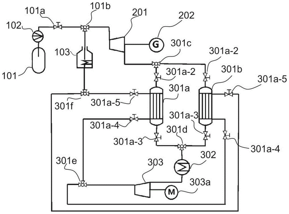
图1为本发明阀门切换的蓄热式回热超临界二氧化碳循环系统的整体结构示意图。FIG. 1 is a schematic diagram of the overall structure of the regenerative regenerative supercritical carbon dioxide cycle system with valve switching according to the present invention.
图2为本发明阀门切换的蓄热式回热超临界二氧化碳循环系统的回热器结构示意图。FIG. 2 is a schematic structural diagram of the regenerator of the regenerative regenerative supercritical carbon dioxide cycle system with valve switching according to the present invention.
具体实施方式Detailed ways
为使本发明的上述目的、特征和优点能够更加明显易懂,下面结合说明书附图对本发明的具体实施方式做详细的说明。In order to make the above objects, features and advantages of the present invention more clearly understood, the specific embodiments of the present invention will be described in detail below with reference to the accompanying drawings.
在下面的描述中阐述了很多具体细节以便于充分理解本发明,但是本发明还可以采用其他不同于在此描述的其它方式来实施,本领域技术人员可以在不违背本发明内涵的情况下做类似推广,因此本发明不受下面公开的具体实施例的限制。In the following description, many specific details are set forth to facilitate a full understanding of the present invention, but the present invention can also be implemented in other ways different from those described herein, and those skilled in the art can do so without departing from the connotation of the present invention. Similar promotion, therefore, the present invention is not limited by the specific embodiments disclosed below.
其次,此处所称的“一个实施例”或“实施例”是指可包含于本发明至少一个实现方式中的特定特征、结构或特性。在本说明书中不同地方出现的“在一个实施例中”并非均指同一个实施例,也不是单独的或选择性的与其他实施例互相排斥的实施例。Second, reference herein to "one embodiment" or "an embodiment" refers to a particular feature, structure, or characteristic that may be included in at least one implementation of the present invention. The appearances of "in one embodiment" in various places in this specification are not all referring to the same embodiment, nor are they separate or selectively mutually exclusive from other embodiments.
再其次,本发明结合示意图进行详细描述,在详述本发明实施例时,为便于说明,表示器件结构的剖面图会不依一般比例作局部放大,而且所述示意图只是示例,其在此不应限制本发明保护的范围。此外,在实际制作中应包含长度、宽度及深度的三维空间尺寸。Thirdly, the present invention is described in detail with reference to the schematic diagrams. When describing the embodiments of the present invention in detail, for the convenience of explanation, the cross-sectional views showing the device structure will not be partially enlarged according to the general scale, and the schematic diagrams are only examples, which should not be used here. Limit the scope of protection of the present invention. In addition, the three-dimensional spatial dimensions of length, width and depth should be included in the actual production.
实施例1Example 1
参照图1,为本发明第一个实施例,提供了一种阀门切换的蓄热式回热超临界二氧化碳循环系统,此系统包括加热组件100、发电组件200和储热组件 300,其中,加热组件100,包括储存罐101、与所述储存罐101连接的泵102、与所述泵102连接的热源103;发电组件200,与所述泵102连接,包括透平 201和与所述透平201连接的发电机202;储热组件300,与所述透平201连接,包括储热件301、与所述储热件301连接的冷却器302、与所述冷却器302连接的压缩机303。Referring to FIG. 1 , for the first embodiment of the present invention, a valve-switched regenerative regenerative supercritical carbon dioxide cycle system is provided. The system includes a heating assembly 100 , a power generation assembly 200 and a heat storage assembly 300 , wherein the heating The assembly 100 includes a
其中,加热组件100能够对超临界二氧化碳工质加热,并为整个系统提供二氧化碳,发电组件200通过超临界二氧化碳带动发电机202发电,储热组件 300用于对超临界二氧化碳热量进行吸收蓄热,并降温与加压,之后重新回到热源103处进行循环。The heating component 100 can heat the supercritical carbon dioxide working medium and provide carbon dioxide for the entire system, the power generation component 200 drives the
储存罐101内存储有超临界二氧化碳,泵102驱动二氧化碳流入系统,热源103将二氧化碳加热,加热后的超临界二氧化碳工质进入透平201内做功,透平201带动发电机202发电,储热件301用于对超临界二氧化碳热量进行吸收蓄热,冷却器302将二氧化碳降温,之后二氧化碳进入压缩机303进行加压。The
实施例2Example 2
参照图1~2,为本发明的第二个实施例,该实施例不同于第一个实施例的是:所述加热组件100、发电组件200和储热组件300通过管道连接。所述泵 102与热源103之间设置有第一调节阀101a和第一三通阀101b,所述第一三通阀101b连接第一调节阀101a、热源103和透平201。1-2, it is the second embodiment of the present invention, which is different from the first embodiment in that the heating assembly 100, the power generation assembly 200 and the heat storage assembly 300 are connected by pipes. A first regulating
所述储热件301包括第一回热器301a和第二回热器301b,所述第一回热器301a、第二回热器301b和透平201之间连接有第二三通阀301c。所述第一回热器301a和第二回热器301b分别设置有填料口301a-1、蓄热入口调节阀 301a-2、蓄热出口调节阀301a-3、放热入口调节阀301a-4和放热出口调节阀 301a-5,所述第一回热器301a和第二回热器301b内还放置有填充料301a-6。The heat storage element 301 includes a
所述第一回热器301a和第二回热器301b的蓄热入口调节阀301a-2与第二三通阀301c连接,其蓄热出口调节阀301a-3与冷却器302通过第三三通阀301d 连接,其放热入口调节阀301a-4与压缩机303通过第四三通阀301e连接,其放热出口调节阀301a-5与热源103通过第五三通阀301f连接。The heat storage
所述压缩机303还连接有电动机303a。所述热源103采用太阳能、核反应堆、工业余热等温度为400~750℃的热源。所述填充料301a-6填充度取值范围为0.3~0.5,且其可选择刚玉球、铸造陶瓷和合金材料等。所述第一回热器301a 和第二回热器301b为一体成型,采用不锈钢材料制成。The
相较于实施例1,进一步的,当机组启动时,第一调节阀101a打开,超临界二氧化碳工质在泵102的驱动下从二氧化碳储存罐101中流入系统,当工质补充完成后,关闭泵102和第一调节阀101a;热源103开始对流入的超临界二氧化碳工质进行加热,加热后的超临界二氧化碳工质进入透平201做功,带动发电机202发电;此时,第一回热器301a上的蓄热入口调节阀301a-2和蓄热出口调节阀301a-3打开,第二回热器301b的蓄热入口调节阀301a-2和蓄热出口调节阀301a-3关闭,第二三通阀301c和第三三通阀301d与第一回热器301a 相连的一侧打开,与第二回热器301b相连的一侧关闭,第一回热器301a的放热入口调节阀301a-4和放热出口调节阀301a-5关闭,第二回热器301b的放热入口调节阀301a-4和放热出口调节阀301a-5打开,第四三通阀301d与第一回热器301a相连的一侧关闭,与第二回热器301b相连的一侧打开,第五三通阀 301e与第二回热器301b相连的一侧打开,与第一回热器301a相连的一侧关闭。Compared with Example 1, further, when the unit is started, the
超临界二氧化碳工质经过热源103加热,进入透平201做功,并带动发电机202发电,做功完成后超临界二氧化碳从透平201排出,经过第二三通阀301c 和第一回热器301a的蓄热入口调节阀301a-2进入第一回热器301a进行蓄热,高温超临界二氧化碳工质的热量第一回热器301a储存温度降低,降温后的超临界二氧化碳工质经过第一回热器301a的蓄热出口调节阀301a-3流入冷却器 302温度继续降低,降温后的超临界二氧化碳进入压缩机303进行加压,压力升高后的超临界二氧化碳工质经过第四三通阀301d和第二回热器301b的放热入口调节阀301a-4流入第二回热器301b,此时第二回热器301b未经过蓄热,第二回热器301b只起到连通回路的作用,所以超临界二氧化碳工质经过第二回热器301b从其放热出口调节阀301a-5流出,经过第五三通阀301e进入热源 103进行下一次循环。The supercritical carbon dioxide working medium is heated by the
当机组启动一段时间后,第一回热器301a中热量储存完成,系统进行阀门切换,此时,第一回热器301a的蓄热入口调节阀301a-2和蓄热出口调节阀 301a-3关闭,第二回热器301b的蓄热入口调节阀301a-2和蓄热出口调节阀 301a-3打开,第二三通阀301c与与第一回热器301a相连的一侧关闭,与第二回热器301b相连的一侧打开,第三三通阀301c与第一回热器301a相连的一侧关闭,与第二回热器301b相连的一侧打开;在放热侧,第一回热器301a的放热出口调节阀301a-5和放热入口调节阀301a-4打开,第二回热器301b的放热入口调节阀301a-4和放热出口调节阀301a-5关闭,第四三通阀301d与第一回热器301a相连的一侧打开,与第二回热器301b相连的一侧关闭,第五三通阀 301e与第一回热器301a相连的一侧打开,与第二回热器301b相连的一侧关闭。After the unit is started for a period of time, the heat storage in the
此时,整个超临界二氧化碳工质的流程为:超临界二氧化碳工质经过热源 103加热,进入透平201做功,并带动发电机202发电,做功完成后超临界二氧化碳从透平201排出,经过第二三通阀301c和第二回热器301b的蓄热入口调节阀301a-2进行蓄热,超临界二氧化碳工质的热量被第二回热器301b储存温度降低,降温后的超临界二氧化碳工质经过蓄热出口调节阀301a-3流入冷却器302温度继续降低,降温后的超临界二氧化碳进入压缩机303进行加压,压力升高后的超临界二氧化碳工质经过第四三通阀301d和第一回热器301a的放热入口调节阀301a-4流入第一回热器301a,超临界二氧化碳工质吸收第一回热器301a之前储存的热量温度升高,升温后的超临界二氧化碳工质从第一回热器301a的放热出口调节阀301a-5排出,经过第五三通阀301e与热源103继续下一次循环。At this time, the entire process of the supercritical carbon dioxide working fluid is as follows: the supercritical carbon dioxide working fluid is heated by the
当机组稳定运行后,系统根据第一回热器301a和第二回热器301b的储热时间进行定时切换,当其中一个蓄热式回热器热量蓄满后,关闭其蓄热侧阀门,该蓄热式回热器切换至放热回路进行放热;另一个蓄热式回热器打开蓄热侧阀门进行蓄热,关闭放热侧阀门;如此循环切换达到蓄热回热的目的。When the unit is running stably, the system switches according to the heat storage time of the
蓄热式回热器的蓄热回热箱体采用不锈钢作为管壁材料,内部填充的蓄热填充料301a-6为直径6mm的球状储热填充料,从上方的填料口301a-1加入第一回热器301a和第二回热器301b,填充料在储热回热箱中的填充度一般在 0.3~0.5之间,可根据实际情况进行调整,其中的蓄热入口调节阀301a-2、蓄热出口调节阀301a-3、放热入口调节阀301a-4和放热出口调节阀301a-5与整个系统中的蓄热回路侧和放热回路侧调节阀对应,与整个储热式回热器焊接在一起保证系统的密封性。The regenerative regenerator box of the regenerative regenerator adopts stainless steel as the tube wall material, and the
其余结构与实施例1的结构相同。The rest of the structure is the same as that of
重要的是,应注意,在多个不同示例性实施方案中示出的本申请的构造和布置仅是例示性的。尽管在此公开内容中仅详细描述了几个实施方案,但参阅此公开内容的人员应容易理解,在实质上不偏离该申请中所描述的主题的新颖教导和优点的前提下,许多改型是可能的(例如,各种元件的尺寸、尺度、结构、形状和比例、以及参数值(例如,温度、压力等)、安装布置、材料的使用、颜色、定向的变化等)。例如,示出为整体成形的元件可以由多个部分或元件构成,元件的位置可被倒置或以其它方式改变,并且分立元件的性质或数目或位置可被更改或改变。因此,所有这样的改型旨在被包含在本发明的范围内。可以根据替代的实施方案改变或重新排序任何过程或方法步骤的次序或顺序。在权利要求中,任何“装置加功能”的条款都旨在覆盖在本文中所描述的执行所述功能的结构,且不仅是结构等同而且还是等同结构。在不背离本发明的范围的前提下,可以在示例性实施方案的设计、运行状况和布置中做出其他替换、改型、改变和省略。因此,本发明不限制于特定的实施方案,而是扩展至仍落在所附的权利要求书的范围内的多种改型。It is important to note that the construction and arrangement of the present application shown in the various exemplary embodiments are merely exemplary. Although only a few embodiments have been described in detail in this disclosure, those who refer to this disclosure will readily appreciate that many modifications are possible without materially departing from the novel teachings and advantages of the subject matter described in this application are possible (eg, changes in size, dimensions, structure, shape, and proportions of various elements, as well as parameter values (eg, temperature, pressure, etc.), mounting arrangement, use of materials, color, orientation, etc.). For example, elements shown as integrally formed may be constructed of multiple parts or elements, the positions of elements may be inverted or otherwise varied, and the nature or number or positions of discrete elements may be altered or varied. Accordingly, all such modifications are intended to be included within the scope of this invention. The order or sequence of any process or method steps may be varied or re-sequenced according to alternative embodiments. In the claims, any "mean-plus-function" clause is intended to cover the structures described herein as performing the recited function and not only structural equivalents but also equivalent structures. Other substitutions, modifications, changes and omissions may be made in the design, operation and arrangement of the exemplary embodiments without departing from the scope of the present invention. Therefore, the present invention is not limited to a particular embodiment, but extends to various modifications still falling within the scope of the appended claims.
此外,为了提供示例性实施方案的简练描述,可以不描述实际实施方案的所有特征(即,与当前考虑的执行本发明的最佳模式不相关的那些特征,或于实现本发明不相关的那些特征)。Furthermore, in order to provide a concise description of example embodiments, all features of an actual implementation (ie, those that are not relevant to the best mode currently considered for carrying out the invention, or those that are not relevant for carrying out the invention, may not be described in order to provide a concise description of example embodiments) feature).
应理解的是,在任何实际实施方式的开发过程中,如在任何工程或设计项目中,可做出大量的具体实施方式决定。这样的开发努力可能是复杂的且耗时的,但对于那些得益于此公开内容的普通技术人员来说,不需要过多实验,所述开发努力将是一个设计、制造和生产的常规工作。It should be appreciated that during the development of any actual implementation, such as in any engineering or design project, numerous implementation-specific decisions may be made. Such a development effort may be complex and time-consuming, but would be a routine undertaking of design, fabrication, and production without undue experimentation for those of ordinary skill having the benefit of this disclosure .
应说明的是,以上实施例仅用以说明本发明的技术方案而非限制,尽管参照较佳实施例对本发明进行了详细说明,本领域的普通技术人员应当理解,可以对本发明的技术方案进行修改或者等同替换,而不脱离本发明技术方案的精神和范围,其均应涵盖在本发明的权利要求范围当中。。It should be noted that the above embodiments are only used to illustrate the technical solutions of the present invention and not to limit them. Although the present invention has been described in detail with reference to the preferred embodiments, those of ordinary skill in the art should understand that the technical solutions of the present invention can be Modifications or equivalent substitutions without departing from the spirit and scope of the technical solutions of the present invention should be included in the scope of the claims of the present invention. .
Claims (5)
Priority Applications (1)
| Application Number | Priority Date | Filing Date | Title |
|---|---|---|---|
| CN202011566771.9A CN112683093B (en) | 2020-12-25 | 2020-12-25 | Heat accumulating type backheating supercritical carbon dioxide circulating system with valve switching |
Applications Claiming Priority (1)
| Application Number | Priority Date | Filing Date | Title |
|---|---|---|---|
| CN202011566771.9A CN112683093B (en) | 2020-12-25 | 2020-12-25 | Heat accumulating type backheating supercritical carbon dioxide circulating system with valve switching |
Publications (2)
| Publication Number | Publication Date |
|---|---|
| CN112683093A CN112683093A (en) | 2021-04-20 |
| CN112683093B true CN112683093B (en) | 2022-10-18 |
Family
ID=75451795
Family Applications (1)
| Application Number | Title | Priority Date | Filing Date |
|---|---|---|---|
| CN202011566771.9A Active CN112683093B (en) | 2020-12-25 | 2020-12-25 | Heat accumulating type backheating supercritical carbon dioxide circulating system with valve switching |
Country Status (1)
| Country | Link |
|---|---|
| CN (1) | CN112683093B (en) |
Families Citing this family (3)
| Publication number | Priority date | Publication date | Assignee | Title |
|---|---|---|---|---|
| CN113294769B (en) * | 2021-04-27 | 2025-09-26 | 广东工业大学 | Supercritical-transcritical CO2 coal-fired power generation system adapted to different geographical environments, climates and loads |
| CN115479789B (en) * | 2021-06-16 | 2025-03-04 | 江苏金通灵光核能源科技有限公司 | A performance test platform for supercritical carbon dioxide printed circuit board heat exchangers |
| CN116181441A (en) * | 2023-01-17 | 2023-05-30 | 华中科技大学 | A testing system for dynamic characteristics of supercritical carbon dioxide |
Citations (5)
| Publication number | Priority date | Publication date | Assignee | Title |
|---|---|---|---|---|
| US20100024421A1 (en) * | 2006-12-08 | 2010-02-04 | United Technologies Corporation | Supercritical co2 turbine for use in solar power plants |
| CN107387179A (en) * | 2017-07-19 | 2017-11-24 | 东南大学 | One kind is coupled with CO2The supercritical CO of energy-storage units2Brayton cycle electricity generation system |
| CN207349038U (en) * | 2017-01-13 | 2018-05-11 | 华北电力大学 | One kind is based on carbon dioxide Brayton cycle tower type solar energy thermal power generation peak regulation system |
| CN109340066A (en) * | 2018-10-16 | 2019-02-15 | 中国科学院工程热物理研究所 | A supercritical carbon dioxide solar power generation and energy storage integrated system |
| CN111878330A (en) * | 2020-09-02 | 2020-11-03 | 西安热工研究院有限公司 | double-Brayton combined cycle solar power generation system and method with heat storage function |
-
2020
- 2020-12-25 CN CN202011566771.9A patent/CN112683093B/en active Active
Patent Citations (5)
| Publication number | Priority date | Publication date | Assignee | Title |
|---|---|---|---|---|
| US20100024421A1 (en) * | 2006-12-08 | 2010-02-04 | United Technologies Corporation | Supercritical co2 turbine for use in solar power plants |
| CN207349038U (en) * | 2017-01-13 | 2018-05-11 | 华北电力大学 | One kind is based on carbon dioxide Brayton cycle tower type solar energy thermal power generation peak regulation system |
| CN107387179A (en) * | 2017-07-19 | 2017-11-24 | 东南大学 | One kind is coupled with CO2The supercritical CO of energy-storage units2Brayton cycle electricity generation system |
| CN109340066A (en) * | 2018-10-16 | 2019-02-15 | 中国科学院工程热物理研究所 | A supercritical carbon dioxide solar power generation and energy storage integrated system |
| CN111878330A (en) * | 2020-09-02 | 2020-11-03 | 西安热工研究院有限公司 | double-Brayton combined cycle solar power generation system and method with heat storage function |
Also Published As
| Publication number | Publication date |
|---|---|
| CN112683093A (en) | 2021-04-20 |
Similar Documents
| Publication | Publication Date | Title |
|---|---|---|
| CN112554984B (en) | A constant pressure pumped compressed air energy storage system with heat storage and its operation method | |
| WO2022166031A1 (en) | Packed bed-based compressed air energy storage system and method | |
| CN110118160B (en) | Solar supercritical carbon dioxide Brayton cycle system | |
| CN112228853B (en) | Porous medium heat transfer and storage device, heat transfer and storage power generation system and energy storage power station | |
| CN106532414A (en) | Phase-change cooling-storage type liquid cooling source for large-power laser | |
| CN114857973B (en) | Electric heating energy storage system and heat exchange method | |
| CN219081667U (en) | Kano battery energy storage and CO2 ultra-transcritical power cycle combined power generation system | |
| CN111075529B (en) | Brayton cycle power generation system suitable for pulse type fusion reactor | |
| CN115333248A (en) | Liquid carbon dioxide energy storage system for island reef and microgrid system | |
| CN112683093A (en) | Heat accumulating type backheating supercritical carbon dioxide circulating system with valve switching | |
| CN116281852A (en) | Solid-state hydrogen storage system based on hydrogen self-circulation heat exchange | |
| CN106481522B (en) | A Closed Helium Turbine Tower Solar Thermal Power Generation System with Thermal Storage | |
| CN116025439A (en) | A transcritical carbon dioxide heat pump molten salt heat storage power generation system | |
| CN106499601B (en) | Closed Helium Turbine Tower Solar Thermal Power Generation System with Thermal Storage | |
| CN110513166B (en) | Regenerative alternate energy storage power generation system | |
| CN119133512A (en) | A microchannel solid-state hydrogen storage thermal management system | |
| WO2025194780A1 (en) | Compressed gas energy storage system capable of constant-pressure gas storage | |
| CN209281902U (en) | Switchable type supercritical carbon dioxide circulating thermoelectric co-feeding system for sodium-cooled fast reactor | |
| CN118564314A (en) | A Brayton cycle heat pump power storage system using isothermal compression | |
| CN112582084A (en) | Micro-stack adopting superconducting heat pipe | |
| CN109441582B (en) | Recompression cycle compact supercritical carbon dioxide cycle energy supply system for small sodium reactors | |
| CN116122927A (en) | Carnot battery energy storage and CO 2 Combined power generation system of super-transcritical power cycle | |
| CN114658504A (en) | Multistage compressed air energy storage and heat pump electricity storage coupling energy storage system | |
| CN220187509U (en) | Time-staggered shared heat exchanger system and compressed air energy storage power station | |
| CN118602300A (en) | A system for reducing exergy loss of CAES hot water storage system and its use method |
Legal Events
| Date | Code | Title | Description |
|---|---|---|---|
| PB01 | Publication | ||
| PB01 | Publication | ||
| SE01 | Entry into force of request for substantive examination | ||
| SE01 | Entry into force of request for substantive examination | ||
| GR01 | Patent grant | ||
| GR01 | Patent grant |