CN112683098B - Dislocation dotting oil cooler pipe - Google Patents
Dislocation dotting oil cooler pipe Download PDFInfo
- Publication number
- CN112683098B CN112683098B CN202011640095.5A CN202011640095A CN112683098B CN 112683098 B CN112683098 B CN 112683098B CN 202011640095 A CN202011640095 A CN 202011640095A CN 112683098 B CN112683098 B CN 112683098B
- Authority
- CN
- China
- Prior art keywords
- oil cooler
- bending part
- pipe
- groove
- tube
- Prior art date
- Legal status (The legal status is an assumption and is not a legal conclusion. Google has not performed a legal analysis and makes no representation as to the accuracy of the status listed.)
- Active
Links
Images


Classifications
-
- Y—GENERAL TAGGING OF NEW TECHNOLOGICAL DEVELOPMENTS; GENERAL TAGGING OF CROSS-SECTIONAL TECHNOLOGIES SPANNING OVER SEVERAL SECTIONS OF THE IPC; TECHNICAL SUBJECTS COVERED BY FORMER USPC CROSS-REFERENCE ART COLLECTIONS [XRACs] AND DIGESTS
- Y02—TECHNOLOGIES OR APPLICATIONS FOR MITIGATION OR ADAPTATION AGAINST CLIMATE CHANGE
- Y02T—CLIMATE CHANGE MITIGATION TECHNOLOGIES RELATED TO TRANSPORTATION
- Y02T10/00—Road transport of goods or passengers
- Y02T10/10—Internal combustion engine [ICE] based vehicles
- Y02T10/12—Improving ICE efficiencies
Landscapes
- Heat-Exchange Devices With Radiators And Conduit Assemblies (AREA)
Abstract
本发明公开一种错位打点的油冷器管,包括管体,所述管体上、下表面分别设有轴向相互垂直的第一凹槽和第二凹槽,管体上还设有内陷的加强筋。管体两端还设有加强片或弯折部。本发明的错位打点油冷器管内有多条过油通道,十字错位的设计增强了扰流作用,使得本发明的油冷器管无需使用内翅片就能有较好的扰流效果。本发明的错位打点油冷器管有较大的工作压力,并且能保证油冷器管进出端的压力强度,使润滑油顺利通过。且无需使用内翅片,降低了管体的重量,有利于降低油冷器的整体重量,高强度的油冷器管也延长了油冷器的使用寿命。本发明结构简单,安装方便,润滑油冷却效率高,原材料成本低,具有良好的应用前景。
The invention discloses an oil cooler tube with misaligned dots. sunken ribs. Both ends of the pipe body are also provided with reinforcing pieces or bending parts. There are multiple oil passages in the tube of the misplaced dotted oil cooler of the present invention, and the design of the cross dislocation enhances the turbulence effect, so that the oil cooler tube of the present invention can have a better turbulence effect without using inner fins. The misplaced dotted oil cooler tube of the present invention has relatively high working pressure, and can ensure the pressure strength at the inlet and outlet ends of the oil cooler tube, so that lubricating oil can pass through smoothly. And without using inner fins, the weight of the tube body is reduced, which is beneficial to reduce the overall weight of the oil cooler, and the high-strength oil cooler tube also prolongs the service life of the oil cooler. The invention has simple structure, convenient installation, high lubricating oil cooling efficiency, low raw material cost and good application prospect.
Description
技术领域technical field
本发明涉及汽车散热器组件技术领域,具体地涉及一种错位打点的油冷器管。The invention relates to the technical field of automobile radiator components, in particular to an oil cooler tube with misplaced dots.
背景技术Background technique
汽车在行驶时,齿轮箱因为动力的传输,其中容置的润滑油温度会不断上升,如果润滑油温度过高,则有可能令润滑油沸腾而失去润滑作用,从而使得齿轮易于磨损,如何确保齿轮箱中的润滑油温度不会过高,成为一个相当重要的课题。现有的汽车结构配置中,均会设有油冷器管,用于冷却润滑油,保证油温在正常工作范围之内。When the car is running, the temperature of the lubricating oil contained in the gearbox will continue to rise due to the transmission of power. If the temperature of the lubricating oil is too high, it may cause the lubricating oil to boil and lose its lubricating effect, thus making the gears easy to wear. How to ensure The temperature of the lubricating oil in the gearbox will not be too high, which becomes a very important issue. In the existing structural configuration of automobiles, oil cooler tubes are provided to cool lubricating oil and ensure that the oil temperature is within the normal working range.
现有技术的汽车油冷器,包括油冷器管体,油冷器管体具有内外双层管壁,内外双层管壁的管端密封封闭,内外双层管壁的中间围出过油空腔,油冷器管体外层管壁的一端设有进油口,另一端设有出油口,进出油口均相通于过油空腔,在进行机油冷却时油冷器管体的内孔及外壁与冷却水接触。但是上述管体的冷却面积有限,不能实现更好的机油冷却效果。The automobile oil cooler in the prior art includes an oil cooler pipe body, the oil cooler pipe body has inner and outer double-layer pipe walls, the pipe ends of the inner and outer double-layer pipe walls are sealed and closed, and the middle of the inner and outer double-layer pipe walls surrounds the oil passage. One end of the outer tube wall of the oil cooler tube is provided with an oil inlet, and the other end is provided with an oil outlet. The oil inlet and outlet are both connected to the oil passing cavity. The hole and the outer wall are in contact with the cooling water. However, the cooling area of the above-mentioned pipe body is limited, and a better oil cooling effect cannot be achieved.
其次,将油冷器管体装配成油冷器时,由于结构设计不合理,导致焊接强度不足,使得油冷管体在工作时能承受的工作压力较小,并且油冷管体进出端的压力强度也较弱,不能满足使用要求。因此,增强油冷器管体的应用强度,是提高油冷器性能的一个关键。Secondly, when assembling the oil cooler tube body into an oil cooler, due to the unreasonable structural design, the welding strength is insufficient, so that the working pressure that the oil cooling tube body can withstand during work is small, and the pressure at the inlet and outlet ends of the oil cooling tube body The strength is also weak and cannot meet the requirements of use. Therefore, enhancing the application strength of the oil cooler tube body is a key to improving the performance of the oil cooler.
发明内容Contents of the invention
针对现有技术的不足,本发明提供了一种错位打点的油冷器管。Aiming at the deficiencies of the prior art, the invention provides an oil cooler tube with misplaced dots.
为实现上述目的,本发明提供如下技术方案:To achieve the above object, the present invention provides the following technical solutions:
一种错位打点的油冷器管,包括管体,所述管体上表面沿管体轴向设有多个由管壁向内凹陷形成的第一凹槽,管体下表面设有多个由管壁向内凹陷形成的第二凹槽;第一凹槽底部与第二凹槽底部焊接;An oil cooler tube with misplaced dots, including a tube body, the upper surface of the tube body is provided with a plurality of first grooves formed by the inward depression of the tube wall along the axial direction of the tube body, and the lower surface of the tube body is provided with a plurality of A second groove formed by the inward depression of the pipe wall; the bottom of the first groove is welded to the bottom of the second groove;
所述第一凹槽的轴向和第二凹槽的轴向相垂直且它们分别与管体轴线的夹角为大于0°,小于90°;The axial direction of the first groove is perpendicular to the axial direction of the second groove, and the included angles between them and the axis of the pipe body are greater than 0° and less than 90°;
所述第一凹槽设有2n列,第二凹槽的数量、长度、宽度和分布位置与第一凹槽相同,n为正整数;The first groove is provided with 2n columns, the number, length, width and distribution position of the second groove are the same as the first groove, and n is a positive integer;
当n等于1时,两列第一凹槽之间设有1条加强筋,所述加强筋由管体向内凹陷形成,所述加强筋底部与管体内壁抵接;When n is equal to 1, a reinforcing rib is provided between the two rows of first grooves, the reinforcing rib is formed by inward depression of the pipe body, and the bottom of the reinforcing rib abuts against the inner wall of the pipe;
当n≥2时,管体上设有n条加强筋,每隔2列第一凹槽就设有1条加强筋,且相邻2条加强筋的凹陷方向相反。When n≥2, n reinforcing ribs are provided on the pipe body, one reinforcing rib is provided every second row of the first groove, and the concave directions of the adjacent two reinforcing ribs are opposite.
优选地,所述第一凹槽的长度为0.5-1.5mm。Preferably, the length of the first groove is 0.5-1.5mm.
优选地,所述第一凹槽的宽度为0.2-0.8mm。Preferably, the width of the first groove is 0.2-0.8mm.
优选地,所述管体的宽度为10-250mm,厚度不小于3mm。Preferably, the pipe body has a width of 10-250mm and a thickness of not less than 3mm.
优选地,所述加强筋的凹陷面相贴。Preferably, the concave surfaces of the reinforcing ribs are in close contact with each other.
优选地,所述管体两侧内壁设有加强片。Preferably, reinforcing sheets are provided on the inner walls of both sides of the pipe body.
优选地,所述管体为一块片体弯折而成,片体的弯折处设有第一弯折部,片体的2个自由端分别设有第二弯折部和第三弯折部。Preferably, the pipe body is formed by bending a piece of sheet body, a first bending part is provided at the bending part of the sheet body, and a second bending part and a third bending part are respectively provided at two free ends of the sheet body department.
优选地,所述第一弯折部由片体折叠2-6层而成。Preferably, the first bending portion is formed by folding 2-6 layers of sheet body.
优选地,所述第二弯折部和第三弯折部均由片体的2个自由端向管体内折叠2-6层而成,且第二弯折部、第三弯折部的高度均为第一弯折部高度的一半,第一弯折部、第二弯折部、第三弯折部的折叠层数及折叠的厚度相同。Preferably, both the second bending part and the third bending part are formed by folding 2-6 layers of the two free ends of the sheet body into the tube body, and the height of the second bending part and the third bending part is Both are half the height of the first bending part, and the number of folded layers and the folded thickness of the first bending part, the second bending part and the third bending part are the same.
本发明由于采用了上述技术方案,具备以下有益效果:The present invention has the following beneficial effects due to the adoption of the above technical solution:
1、现有的油冷器管是在普通的焊接铝管内塞入翅片(如图7),再装配成油冷器使用。该种管型耐压能力弱,管体中部容易受到挤压变形,装配而成的油冷器强度差,内翅片易晃动,影响换热效果。1. The existing oil cooler tubes are filled with fins in ordinary welded aluminum tubes (as shown in Figure 7), and then assembled into oil coolers for use. This type of tube type has weak pressure resistance, and the middle part of the tube body is easily squeezed and deformed. The assembled oil cooler has poor strength, and the inner fins are easy to shake, which affects the heat exchange effect.
本发明的错位打点油冷器管在管体的上、下面设置了错位方向的凹槽,且上、下2个凹槽的底部相接触,热油从加强筋与其相近的第一凹槽及第二凹槽组成的不完全封闭通道,或者加强筋与加强筋、加强筋与管体侧壁之间通过。现有的打点油冷器管打点为圆点,焊合时容易对不准,焊点小,若工作压力过大甚至有可能焊合的两点被冲击脱离。十字错位的设计可以让凹槽底部的接触点能准确接触,提高焊合率,保证管体的正常工作。且十字错位的打点设计增强了扰流作用,使得本发明的油冷器管无需使用内翅片就能有较好的扰流效果,降低管材重量和油冷器重量,且不降低换热效率。此外,本发明的油冷器管还设计了加强筋,一方面利用管体自身材料增强管体强度,且不增加管体的外体积,另一方面还可组成完全/不完全的过油通道,进一步将热油分割成更小的紊流,避免热油流动对管体冲击性过大,引发油冷器振动。The misplaced oil cooler tube of the present invention is provided with grooves in the dislocation direction on the upper and lower sides of the pipe body, and the bottoms of the upper and lower grooves are in contact, and the hot oil flows from the reinforcing rib to the first groove close to it and The incompletely closed passage formed by the second groove, or the passage between the reinforcing rib and the reinforcing rib, or between the reinforcing rib and the side wall of the pipe body. The dots of the existing dotted oil cooler tubes are round dots, which are easy to be misaligned during welding, and the solder joints are small. If the working pressure is too high, the two welded dots may even be separated by impact. The design of the cross dislocation can make the contact point at the bottom of the groove contact accurately, improve the welding rate, and ensure the normal operation of the pipe body. And the dot design of the cross dislocation enhances the turbulence effect, so that the oil cooler tube of the present invention can have a better turbulence effect without using inner fins, reducing the weight of the tube and the weight of the oil cooler without reducing the heat exchange efficiency . In addition, the oil cooler tube of the present invention is also designed with reinforcing ribs. On the one hand, the material of the tube body is used to enhance the strength of the tube body without increasing the external volume of the tube body. On the other hand, it can also form a complete/incomplete oil passage. , to further divide the hot oil into smaller turbulent flows, so as to avoid excessive impact of hot oil flow on the pipe body and cause vibration of the oil cooler.
2、现在的油冷器是在散热带两边焊上加强条和上、下护板,即由独立的片体和散热带焊接而成(如图8),焊缝多,结构复杂,生产工艺繁琐,效率低,在使用过程容易发生泄漏、变形等问题。本发明还在管体两端设置了加强片,可直接接使用代替加强条和上、下护板,用本发明的油冷器管取代如图7的旧结构的油冷器,体积大大减小,管体采用一个铝合金的金属片体一次弯折成型,材质轻便,生产上容易实现弯折,大大节约了加工时间,生产效率高,管体的整体强度高,使用过程不容易发生泄漏。此外,该结构的油冷管也可用于装配普通的油冷器。2. The current oil cooler is welded with reinforcing strips and upper and lower guard plates on both sides of the heat dissipation belt, that is, it is welded by independent sheet body and heat dissipation belt (as shown in Figure 8), with many welds, complex structure and difficult production process. It is cumbersome and inefficient, and it is prone to problems such as leakage and deformation during use. The present invention is also equipped with reinforcing sheets at both ends of the pipe body, which can be directly used to replace the reinforcing strips and the upper and lower guard plates, and the oil cooler tube of the present invention is used to replace the oil cooler with the old structure as shown in Figure 7, and the volume is greatly reduced. Small, the tube body is formed by one-time bending of an aluminum alloy metal sheet, the material is light, and it is easy to realize bending in production, which greatly saves processing time, high production efficiency, high overall strength of the tube body, and is not easy to leak during use . In addition, the oil cooling tube of this structure can also be used to assemble ordinary oil coolers.
3、本发明还可在管体两侧设计弯折部,弯折部为片体向管体内折叠3次而成,弯折部类似2个U型开口交错放置然后折叠挤压得到。弯折部同样可在保证管体宽度方向上的厚度较小的情况下,保证了管体的强度,可在将该结构的油冷器管装配成油冷器时,有较大的工作压力,并且保证管进出端的压力强度,使润滑油顺利流入流出。3. In the present invention, bending parts can also be designed on both sides of the tube body. The bending part is formed by folding the sheet body into the tube body three times. The bending part is similar to two U-shaped openings placed alternately and then folded and extruded. The bending part can also ensure the strength of the pipe body while ensuring that the thickness of the pipe body in the width direction is small, and when the oil cooler tube of this structure is assembled into an oil cooler, there is a greater working pressure , and ensure the pressure strength at the inlet and outlet ends of the pipe, so that the lubricating oil can flow in and out smoothly.
由此可见,本发明的错位打点油冷器管,用于装配成油冷器时,使用时有较大的工作压力,并且能保证油冷器管进出端的压力强度,使润滑油顺利流入流出。且无需使用内翅片,减少了整个管体的制造材料,降低了管体的重量,有利于降低油冷器的整体重量,节约了生产成本,高强度的油冷器管也延长了油冷器的使用寿命。发明强度大,可承受较大的工作压力,结构简单,安装方便,润滑油冷却效率高,原材料成本低,具有良好的应用前景。It can be seen that when the oil cooler tube with misplaced dots of the present invention is assembled into an oil cooler, it has a relatively large working pressure and can ensure the pressure strength at the inlet and outlet ends of the oil cooler tube, so that the lubricating oil can flow in and out smoothly. . And there is no need to use inner fins, which reduces the manufacturing materials of the entire pipe body and reduces the weight of the pipe body, which is conducive to reducing the overall weight of the oil cooler and saving production costs. The high-strength oil cooler tube also extends the length of the oil cooler. service life of the device. The invention has the advantages of high strength, high working pressure, simple structure, convenient installation, high lubricating oil cooling efficiency, low cost of raw materials, and good application prospects.
附图说明Description of drawings
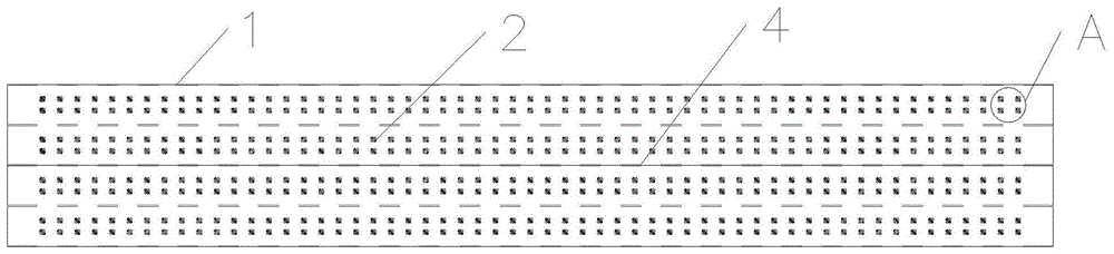
图1为本发明实施例1的油冷器管的整体结构示意图。Fig. 1 is a schematic diagram of the overall structure of an oil cooler tube according to
图2为图1中A处的局部放大视图。Fig. 2 is a partial enlarged view of A in Fig. 1 .
图3为本发明实施例1油冷器管另一角度的结构示意图。Fig. 3 is a structural schematic diagram of another angle of the tube of the oil cooler in
图4为本发明实施例2的油冷器管的结构示意图。Fig. 4 is a schematic structural diagram of an oil cooler tube according to
图5为本发明实施例3第一弯折部的局部放大视图。Fig. 5 is a partially enlarged view of the first bending portion of
图6为本发明实施例3第二弯折部和第三弯折部的局部放大视图。Fig. 6 is a partially enlarged view of the second bending portion and the third bending portion of
图7为现有油冷器管的结构示意图。Fig. 7 is a structural schematic diagram of a conventional oil cooler tube.
图8为现有油冷器的结构示意图。Fig. 8 is a schematic structural diagram of an existing oil cooler.
附图中:1-管体,2-第一凹槽,3-第二凹槽,4-加强筋,5-加强片,6-第一弯折部,7-第二弯折部,8-第三弯折部。In the drawings: 1-pipe body, 2-first groove, 3-second groove, 4-reinforcing rib, 5-reinforcing sheet, 6-first bending part, 7-second bending part, 8 - a third bend.
具体实施方式Detailed ways
为使本发明的目的、技术方案及优点更加清楚明白,以下参照附图并举出优选实施例,对本发明进一步详细说明。然而,需要说明的是,说明书中列出的许多细节仅仅是为了使读者对本发明的一个或多个方面有一个透彻的理解,即便没有这些特定的细节也可以实现本发明的这些方面。In order to make the object, technical solution and advantages of the present invention clearer, the present invention will be described in further detail below with reference to the accompanying drawings and preferred embodiments. However, it should be noted that many of the details listed in the specification are only for readers to have a thorough understanding of one or more aspects of the present invention, and these aspects of the present invention can be implemented even without these specific details.
实施例1Example 1
如图1-3所示,本发明的错位打点油冷器管,包括管体1,所述管体1的厚度为3.0mm,宽度为10.0mm;所述管体1上表面沿管体1轴向设有多个由管壁向内凹陷形成的第一凹槽2,管体1下表面设有多个由管壁向内凹陷形成的第二凹槽3;第一凹槽2底部与第二凹槽3底部焊接。所述第一凹槽2的轴向和第二凹槽3的轴向相垂直且它们分别与管体1轴线的夹角为45°。As shown in Figures 1-3, the misplaced dotted oil cooler tube of the present invention includes a
所述第一凹槽2和第二凹槽3均设有6列,每2列第一凹槽2间隔均匀分布,第一凹槽2的长度为1.5mm,最大宽度为0.4mm,第二凹槽3的数量、长度、宽度与第一凹槽2相同。The
管体2上每隔2列第一凹槽2就设有1条加强筋4,所述加强筋4由管体1向内凹陷形成,所述加强筋4底部与管体1内壁抵接,加强筋4的凹陷面相贴,且相邻2条加强筋4的凹陷方向相反。A reinforcing
实施例2Example 2
如图4所示,本实施例的错位打点油冷器管与实施例1的区别在于,所述管体1两侧内壁设有加强片5。As shown in FIG. 4 , the difference between the misplaced dotted oil cooler tube of this embodiment and the first embodiment is that the inner walls of both sides of the
实施例3Example 3
如图5-6所示,本实施例的错位打点油冷器管与实施例1的区别在于,所述管体1为一块片体弯折而成,片体的弯折处设有第一弯折部6,片体的2个自由端分别设有第二弯折部7和第三弯折部8。所述第一弯折部6由片体折叠3层而成,所述第二弯折部7和第三弯折部8均由片体的2个自由端向管体1内折叠3层而成,且第二弯折部7、第三弯折部8的高度均为第一弯折部6高度的一半,第一弯折部6、第二弯折部7、第三弯折部8折叠后的厚度相同。第二弯折部7、第三弯折部8通过高频焊进行焊接闭合。As shown in Figures 5-6, the difference between the misplaced dotted oil cooler tube of this embodiment and that of
实施例1-3的错位打点油冷器管的使用原理相同,使用时,将油冷器管装配成油冷器,待冷却润滑油从油冷器管一端进入1管体1内的空腔,从加强筋4与其相近的第一凹槽2及第二凹槽3组成的不完全封闭通道,或者加强筋4与管体1侧壁之间通过,十字交错的第一凹槽2和第二凹槽3可降低润滑油的流速,提高扰流程度,使润滑油与油冷器管之间的冷却水充分换热,经过换热冷却的润滑油从油冷器管另一端流出,再次用于齿轮箱的润滑。本发明的冷器管的材质均为铝合金,重量轻,便于加工,节约生产成本。The use principle of the misplaced oil cooler tubes of Examples 1-3 is the same. When in use, the oil cooler tubes are assembled into an oil cooler, and the lubricating oil to be cooled enters the cavity in the
以上所述仅是本发明的优选实施方式,应当指出,对于本技术领域的普通技术人员来说,在不脱离本发明原理的前提下,还可以作出若干改进和润饰,这些改进和润饰也应视为本发明的保护范围。The above is only a preferred embodiment of the present invention, it should be pointed out that for those of ordinary skill in the art, without departing from the principle of the present invention, some improvements and modifications can also be made, and these improvements and modifications should also be It is regarded as the protection scope of the present invention.
Claims (6)
Priority Applications (1)
| Application Number | Priority Date | Filing Date | Title |
|---|---|---|---|
| CN202011640095.5A CN112683098B (en) | 2020-12-31 | 2020-12-31 | Dislocation dotting oil cooler pipe |
Applications Claiming Priority (1)
| Application Number | Priority Date | Filing Date | Title |
|---|---|---|---|
| CN202011640095.5A CN112683098B (en) | 2020-12-31 | 2020-12-31 | Dislocation dotting oil cooler pipe |
Publications (2)
| Publication Number | Publication Date |
|---|---|
| CN112683098A CN112683098A (en) | 2021-04-20 |
| CN112683098B true CN112683098B (en) | 2023-07-04 |
Family
ID=75456718
Family Applications (1)
| Application Number | Title | Priority Date | Filing Date |
|---|---|---|---|
| CN202011640095.5A Active CN112683098B (en) | 2020-12-31 | 2020-12-31 | Dislocation dotting oil cooler pipe |
Country Status (1)
| Country | Link |
|---|---|
| CN (1) | CN112683098B (en) |
Families Citing this family (2)
| Publication number | Priority date | Publication date | Assignee | Title |
|---|---|---|---|---|
| CN113465438A (en) * | 2021-07-29 | 2021-10-01 | 深圳市嘉和达管业有限公司 | S-shaped groove flow guide dislocation dotting tube |
| CN113483592A (en) * | 2021-07-29 | 2021-10-08 | 南宁市安和机械设备有限公司 | Straight groove water conservancy diversion dislocation is got ready and is managed |
Citations (4)
| Publication number | Priority date | Publication date | Assignee | Title |
|---|---|---|---|---|
| JP2000234883A (en) * | 1999-02-17 | 2000-08-29 | Showa Alum Corp | Heat exchanger |
| JP2003247788A (en) * | 2001-12-17 | 2003-09-05 | Showa Denko Kk | Heat exchanger and manufacturing method thereof |
| CN106767090A (en) * | 2016-12-07 | 2017-05-31 | 泰安福星汽车配件有限公司 | A kind of reinforced radiating tube and processing technology |
| CN212154937U (en) * | 2020-04-29 | 2020-12-15 | 南宁市安和机械设备有限公司 | Intercooler tube with reinforcing sheet and reinforcing device thereof |
Family Cites Families (8)
| Publication number | Priority date | Publication date | Assignee | Title |
|---|---|---|---|---|
| DE19803177B4 (en) * | 1998-01-28 | 2005-03-03 | Robert Bosch Gmbh | Process for producing a heat exchanger for fuel-fired water heaters |
| US8683690B2 (en) * | 2006-01-19 | 2014-04-01 | Modine Manufacturing Company | Flat tube, flat tube heat exchanger, and method of manufacturing same |
| US9279624B2 (en) * | 2011-03-01 | 2016-03-08 | Mitsubishi Electric Corporation | Heat exchanger tube with collared fins for enhanced heat transfer |
| CN104792211A (en) * | 2014-01-16 | 2015-07-22 | 泰安鼎鑫冷却器有限公司 | Radiating tube for high-strength condenser |
| EP3006884B1 (en) * | 2014-10-07 | 2017-11-22 | Borgwarner Emissions Systems Spain, S.L.U. | Tube for a heat exchanger |
| CN209013814U (en) * | 2018-08-28 | 2019-06-21 | 无锡逸龙铝热科技有限公司 | A kind of bumps heat radiating flat tube |
| CN110439989A (en) * | 2019-08-20 | 2019-11-12 | 南宁市安和机械设备有限公司 | A kind of new oil cooler pipe |
| CN110439672A (en) * | 2019-08-20 | 2019-11-12 | 南宁市安和机械设备有限公司 | A kind of reinforced intercooler radiating tube |
-
2020
- 2020-12-31 CN CN202011640095.5A patent/CN112683098B/en active Active
Patent Citations (4)
| Publication number | Priority date | Publication date | Assignee | Title |
|---|---|---|---|---|
| JP2000234883A (en) * | 1999-02-17 | 2000-08-29 | Showa Alum Corp | Heat exchanger |
| JP2003247788A (en) * | 2001-12-17 | 2003-09-05 | Showa Denko Kk | Heat exchanger and manufacturing method thereof |
| CN106767090A (en) * | 2016-12-07 | 2017-05-31 | 泰安福星汽车配件有限公司 | A kind of reinforced radiating tube and processing technology |
| CN212154937U (en) * | 2020-04-29 | 2020-12-15 | 南宁市安和机械设备有限公司 | Intercooler tube with reinforcing sheet and reinforcing device thereof |
Also Published As
| Publication number | Publication date |
|---|---|
| CN112683098A (en) | 2021-04-20 |
Similar Documents
| Publication | Publication Date | Title |
|---|---|---|
| US8267163B2 (en) | Radiator tube dimple pattern | |
| CN210272607U (en) | Biplane cooled liquid cooling plate | |
| CN101655321B (en) | High-pressure aluminum plate-fin heat exchanger | |
| CN110439989A (en) | A kind of new oil cooler pipe | |
| EP3677865B1 (en) | Flat tube for microchannel heat exchanger, and microchannel heat exchanger | |
| CN110439990A (en) | A kind of high intensity oil cooler hose | |
| CN112683098B (en) | Dislocation dotting oil cooler pipe | |
| JP7582774B2 (en) | Heat exchanger | |
| CN212055791U (en) | An oil cooler with reinforcing ribs | |
| CN101424490A (en) | Discontinuous double oblique crossing rib strengthened heat exchange method between flat-plates | |
| CN210686932U (en) | High-strength oil cooler pipe | |
| KR20090101008A (en) | Stacked Heat Exchanger | |
| CN112682500B (en) | Oil cooler made of staggered dotting oil cooler tube | |
| CN201876158U (en) | Pipe-type oil radiator | |
| CN214148938U (en) | Plate-fin type flat heat pipe absorption assembly | |
| CN101476832B (en) | Multiple throttling structure of three-fluid plate heat exchanger | |
| CN210004844U (en) | Fin heat exchanger | |
| CN211147419U (en) | Finned tube of air-cooling condenser | |
| CN209588755U (en) | A kind of radiator | |
| RU76433U1 (en) | PLATE HEAT EXCHANGER | |
| CN2417450Y (en) | Integrated, comb like finned tube type heat exchanger body | |
| CN109186279B (en) | Radiator | |
| CN217737974U (en) | High-strength plate-fin heat dissipation core | |
| CN220853239U (en) | Heat exchange tube and heat exchanger | |
| CN219757076U (en) | Heat exchanger |
Legal Events
| Date | Code | Title | Description |
|---|---|---|---|
| PB01 | Publication | ||
| PB01 | Publication | ||
| SE01 | Entry into force of request for substantive examination | ||
| SE01 | Entry into force of request for substantive examination | ||
| GR01 | Patent grant | ||
| GR01 | Patent grant | ||
| PE01 | Entry into force of the registration of the contract for pledge of patent right | ||
| PE01 | Entry into force of the registration of the contract for pledge of patent right |
Denomination of invention: A misaligned oil cooler tube Granted publication date: 20230704 Pledgee: Guangxi Science and Technology Financing Guarantee Co.,Ltd. Pledgor: NANNING ANHE MECHANICAL EQUIPMENT Co.,Ltd. Registration number: Y2025450000079 |