Disclosure of Invention
In order to solve the problems and requirements in the background art, the invention provides a method for improving the reliability of an extra-high voltage direct current access power system based on the number of converters and considering the uncertainty of wind power so as to achieve the aim of improving the operation reliability of the power system.
The technical scheme of the invention is as follows:
the invention comprises the following steps:
step 1: simulating the cumulative probability distribution of the wind speed by using a Weibull distribution model;
step 2: processing the cumulative probability distribution of the wind speed to obtain a simulated wind speed, calculating the simulated wind speed according to the relation between the wind power generation output and the simulated wind speed to obtain the wind power generation output, and realizing uncertainty simulation of the wind power generation output;
and step 3: according to a quasi-steady state model of a current converter in a current converter station of a power system, obtaining an alternating current-direct current coupling equation containing the current converter;
and 4, step 4: obtaining the relation between the number and the power of the converters according to an alternating current-direct current power flow equation of the power system, obtaining power balance equations of nodes where the respective converters are located, and determining a node power balance model of the nodes where the converters are located;
and 5: establishing an optimal scheduling model by using an alternating current-direct current coupling equation containing a current converter and a node power balance model of a node where the current converter is located;
step 6: determining the number of the available converters and the available condition of the generator set according to the reliability parameters of the power system, simultaneously acquiring the wind power generation output, inputting the number of the available converters, the available condition of the generator set and the wind power generation output into an optimal scheduling model, carrying out model solution on the optimal scheduling model according to the data to obtain the load reduction amount, calculating the power supply shortage amount according to the load reduction amount, and finally improving the reliability of the power system according to the power supply shortage amount.
The step 1 specifically comprises the following steps:
the Weibull distribution model simulates the cumulative probability distribution of wind speed, and the formula is as follows:
in the formula, v is a simulated wind speed, c is a scale parameter, k is a shape parameter, y represents the corresponding probability when the simulated wind speed v appears, and y satisfies the condition that y is more than or equal to 0 and less than or equal to 1.
The step 2 specifically comprises the following steps:
the cumulative probability distribution of the wind speed is processed to obtain the wind speed in Weibull distribution, and the wind speed in Weibull distribution is randomly valued to obtain a simulated wind speed, wherein the formula is as follows:
wherein v is a simulated wind speed, c is a scale parameter, k is a shape parameter, the probability y corresponding to the occurrence of the simulated wind speed v satisfies that y is more than or equal to 0 and less than or equal to 1, and the probability y corresponding to the occurrence of the simulated wind speed v is randomly valued in the range of [0,1 ];
calculating the simulated wind speed according to the relationship between the wind power generation output and the simulated wind speed to obtain the wind power generation output corresponding to the simulated wind speed, wherein the relationship between the wind power generation output and the simulated wind speed is as follows:
wherein, PwOutputting power for wind power generation; prRated output of the fan; v. ofciTo cut into the wind speed; v. ofcoTo cut off the wind speed; is the rated wind speed.
The step 3 specifically comprises the following steps:
according to a quasi-steady state model of a converter in a power system converter station, an AC-DC coupling equation containing the converter is established according to the following formula:
in the formula, V
tThe voltage of the alternating current side in the power system; i is
tThe current is the current of an alternating current side in the power system; v
dThe voltage of the direct current side in the power system; i is
dThe current is the current of a direct current side in the power system; k is a radical of
TThe transformation ratio of the converter transformer between the direct current side and the alternating current side; n is a radical of
TThe number of the current converters; x
cIs the equivalent impedance of the inverter; theta
dA control angle set for the converter during commutation;
is the power phase angle on the AC side; k is a radical of
γTo consider the commutation effect coefficient; and pi is the circumferential ratio.
The step 4 specifically comprises the following steps:
obtaining the relation between the number and the power of the converters according to an alternating current-direct current power flow equation of the power system, obtaining the power balance equation of the node where each converter is located by using the relation between the number and the power of the converters and the following formula, and modeling the power balance equation of the node where the converters are located to obtain a power balance equation model of the node where the converters are located;
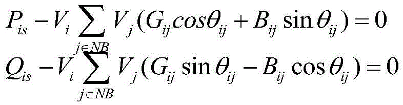
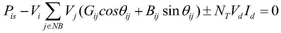
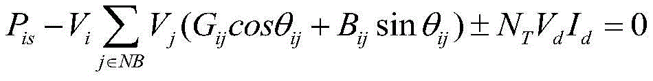
the power balance equation at the node i where the current converter is located in the power system is as follows:
wherein, P
isActive power input for node i; q
isReactive power input for node i; v
iIs the voltage at node i; v
jIs the voltage at node j; NB is a collection of nodes in the power system; g
ijIs the real part of the admittance of line ij; b is
ijThe imaginary part of the admittance for line ij; the line ij is a connecting line between the node i and the node j; theta
ijIs the phase angle difference between node i and node j; n is a radical of
TThe number of the current converters; v
dThe voltage of the direct current side in the power system; i is
dIs the current on the dc side of the power system,
is the power phase angle of the node i on the alternating current side.
The step 5 specifically comprises the following steps:
obtaining constraint conditions by using an alternating current-direct current coupling equation containing a current converter and a node power balance model of a node where the current converter is located, and establishing an optimal scheduling model meeting the constraint conditions; under the condition of given variable data, the optimal scheduling model optimizes the output of the scheduling generator set and reasonably reduces the load, so that the sum of the power generation cost and the load reduction cost of the power system is minimum, wherein the given variable data comprises the number of available converters, the available condition of the generator set and the wind power generation output;
the objective function of the optimal scheduling model is that the sum of the power generation cost and the load reduction cost of the power system is minimum, and the formula is as follows:
in the formula, TC is the sum of the power generation cost and the load reduction cost of the power system; NG is the set of all generator sets in the power system; cn() Is a power generation cost function of the generator set n; pG,nIs the active output of the generator set n; the VOLL is the cost corresponding to the reduction of the unit load of the power system; delta PlaodAn amount of load reduction for the power system;
the constraint conditions specifically comprise node energy balance constraint, node voltage constraint, generator set output constraint, load reduction constraint, line power flow constraint, direct current variable constraint and control station control mode constraint;
1) node energy balance constraints
The node energy balance constraint comprises a power balance equation of a node where the converter is located and a power balance equation of a pure alternating current node, wherein the pure alternating current node is a node without a converter station, and the pure alternating current node comprises a node of the generator set and a common node;
the power balance equation of the node where the converter is located is shown as the following formula:
wherein, P
isActive power input by a node i; q
isReactive power input for node i; v
iIs the voltage at node i; v
jIs the voltage at node j; NB is a collection of nodes in the power system; g
ijIs the real part of the admittance of line ij; b is
ijThe imaginary part of the admittance for line ij; the line ij is a connecting line between the node i and the node j; theta
ijIs the phase angle difference between the node and the node j; n is a radical of
TThe number of the current converters; v
dThe voltage of the direct current side in the power system; i is
dThe current is the current of a direct current side in the power system;
the power phase angle of the node i at the alternating current side;
the power balance equation of the pure alternating current node is shown as follows:
wherein, PisActive power input by a node i; qisReactive power input for node i; viIs the voltage at node i; vjIs the voltage at node j; NB is a collection of nodes in the power system; gijIs the real part of the admittance of line ij; b isijThe imaginary part of the admittance for line ij; the line ij is a connecting line between the node i and the node j;
2) node voltage constraint
Vmin≤Vi≤Vmax
Wherein, ViIs the voltage at node i; vminIs the node voltage lower limit; vmaxIs the upper limit of the node voltage;
3) generator set output restraint
Wherein, P
G,nActive power output of the generator set n; q
G,nActive power output of the generator set n; the active output minimum value of the generator set n is obtained;
is the most active power output of the generator set nA large value;
the minimum reactive output of the generator set n;
the maximum reactive output value of the generator set n is obtained;
4) load reduction constraint
Wherein: delta P
laodAn amount of load reduction for the power system;
is the maximum allowable load reduction of the power system;
5) line flow constraint
Wherein, V
iIs the voltage at node i; v
jIs the voltage at node j; g
ijIs the real part of the admittance of line ij; the line ij is a connecting line between the node i and the node j;
is the lower line capacity limit of line ij;
is the upper line capacity limit of line ij;
6) direct current variable constraint
Vd,k-NT(kT,kVt,k cosθd,k-Xc,kId,k)=0
Wherein, V
d,kFor the DC side voltage, N, at converter station k in the power system
TIs the number of inverters, k
T,kIs the transformation ratio of the converter transformer at converter station k; v
t,kThe voltage of the alternating current side at a converter station k in the power system; theta
d,kSetting a control angle for a converter at a converter station k; x
c,kEquivalent impedance of a current converter at a converter station k; i is
d,kThe current is the current on the direct current side at a converter station k in the power system; k is a radical of
γ,kThe phase change effect coefficient at the converter station k is obtained;
is the power phase angle at the AC side at the converter station k; g
d,kjIs the element of the kth row and the jth column of the node conductance matrix; n is
cIs a set of converter stations; the signs respectively correspond to a rectifier for converting AC into DC and an inverter for converting DC into AC;
7) converter station control mode constraints
Id,k-Icon,k=0
cosθd,k-cosθcon,k=0
Wherein, Icon,kSetting a current setting value for the converter station k in a constant current control mode; thetacon,kAnd setting a control angle setting value for the converter station k in a fixed control angle control mode.
The number of the converter stations in the power system is less than that of the generator sets.
The reliability parameters comprise reliability parameters of the current converter and reliability parameters of the generator set.
The wind power uncertainty is obtained through Weibull distribution simulation, the wind power output condition is obtained through calculation by a method of obtaining random numbers, simulation of the wind power output uncertainty is achieved, in addition, the optimal scheduling model is calculated by using the number of converters and the available condition of the generator set as conditions, and a reliability analysis result is obtained.
The invention has the beneficial effects that:
1) the invention adopts a Weibull distribution simulation method and a converter-based AC/DC model method, which are less influenced by the distribution characteristics of power data, and can effectively converge to an optimal solution by using an interior point method to obtain a stable analysis result.
2) The invention simultaneously considers the uncertainty of wind power generation and the fault probability of the extra-high voltage direct current, carries out reliability simulation analysis on the power system, and carries out effective measures aiming at the analysis result, thereby achieving the purpose of improving the operation reliability of the power system.
Detailed Description
The method of the present invention will be further described with reference to the following examples and the accompanying drawings.
The embodiment of the invention and the implementation process thereof are as follows:
the extra-high voltage refers to a voltage of direct current voltage +/-800 kV and alternating current voltage over 1000 kV.
As shown in fig. 1, step 1: simulating the cumulative probability distribution of wind speed by using a Weibull distribution model according to the wind speed distribution in most areas with a certain rule;
the Weibull distribution model simulates the cumulative probability distribution of wind speed, and the formula is as follows:
in the formula, v is a simulated wind speed, c is a scale parameter, k is a shape parameter, y represents the corresponding probability when the simulated wind speed v appears, and y satisfies the condition that y is more than or equal to 0 and less than or equal to 1. The simulated wind speed v is a variable value, and c and k are determined known parameters.
Step 2: processing the cumulative probability distribution of the wind speed to obtain a simulated wind speed, calculating the simulated wind speed according to the relation between the wind power generation output and the simulated wind speed to obtain the wind power generation output, and realizing uncertainty simulation of the wind power generation output;
the cumulative probability distribution of the wind speed is processed to obtain the wind speed in Weibull distribution, and the wind speed in Weibull distribution is randomly valued to obtain a simulated wind speed, wherein the formula is as follows:
the above formula is a pair formula
Obtaining the inverse result; wherein v is the simulated wind speed, c is the scale parameter, k is the shape parameter, the probability y corresponding to the simulated wind speed v is more than or equal to 0 and less than or equal to 1, and the probability y corresponding to the simulated wind speed v is [0,1]]Randomly taking values in the range of (1);
calculating the simulated wind speed according to the relationship between the wind power generation output and the simulated wind speed to obtain the wind power generation output corresponding to the simulated wind speed, wherein the relationship between the wind power generation output and the simulated wind speed, namely the output characteristic function of the wind power generation is as follows:
wherein, PwOutputting power for wind power generation; prRated output of the fan; v. ofciTo cut into the wind speed; v. ofcoTo cut off the wind speed; v. ofrIs the rated wind speed.
And step 3: according to a quasi-steady state model of a current converter in a current converter station of a power system, obtaining an alternating current-direct current coupling equation containing the current converter;
according to a quasi-steady state model of a converter in a power system converter station, an AC-DC coupling equation containing the converter is established according to the following formula:
in the formula, V
tThe voltage of the alternating current side in the power system; i is
tThe current is the current of an alternating current side in the power system; v
dThe voltage of the direct current side in the power system; i is
dThe current is the current of a direct current side in the power system; k is a radical of
TThe transformation ratio of the converter transformer between the direct current side and the alternating current side; n is a radical of
TThe number of the current converters; x
cIs the equivalent impedance of the inverter; theta
dA control angle set for the converter during commutation;
is the power phase angle on the AC side; k is a radical of
γIn order to consider the commutation effect coefficient, 0.995 is selected in the patent; and pi is the circumferential ratio.
And 4, step 4: obtaining the relation between the number and the power of the converters according to an alternating current-direct current power flow equation of the power system, obtaining power balance equations of nodes where the respective converters are located, and determining a node power balance model of the nodes where the converters are located;
obtaining the relation between the number and the power of converters according to an alternating current-direct current flow equation of a power system, obtaining a power balance equation of a node where the converters are located by using the relation between the number and the power of the converters and a formula, wherein a converter station comprises a plurality of converters, namely the node where the converters are located is the node where the converter station is located, the power system is composed of nodes, the nodes are connection points among branches in the power system, a wind generating set, the converter station and a generating set are all located on the nodes, and modeling is carried out on the power balance equation of the node where the converters are located to obtain a power balance equation model of the node where the converters are located;
the power balance equation at the node i where the current converter is located in the power system is as follows:
wherein, P
isActive power input for node i; q
isReactive power input for node i; v
iIs the voltage at node i; v
jIs the voltage at node j; NB is a collection of nodes in the power system; g
ijIs the real part of the admittance of line ij; b is
ijThe imaginary part of the admittance for line ij; the line ij is a connecting line between the node i and the node j; theta
ijIs the phase angle difference between node i and node j; n is a radical of
TThe number of the current converters; v
dThe voltage of the direct current side in the power system; i is
dIs the current on the dc side of the power system,
is the power phase angle of the node i on the alternating current side.
And 5: establishing an optimal scheduling model by using an alternating current-direct current coupling equation containing a current converter and a node power balance model of a node where the current converter is located;
obtaining constraint conditions by using an alternating current-direct current coupling equation containing a current converter and a node power balance model of a node where the current converter is located, and establishing an optimal scheduling model meeting the constraint conditions; under the condition of given variable data, the optimal scheduling model optimizes the output of the scheduling generator set and reasonably reduces the load, so that the sum of the power generation cost and the load reduction cost of the power system is minimum, wherein the given variable data comprises the number of available converters, the available condition of the generator set and the wind power generation output;
the objective function of the optimal scheduling model is that the sum of the power generation cost and the load reduction cost of the power system is minimum, and the formula is as follows:
in the formula, TC is the sum of the power generation cost and the load reduction cost of the power system; NG is the set of all generator sets in the power system; cn() Is a power generation cost function of the generator set n; pG,nIs the active output of the generator set n; the VOLL is the cost corresponding to the reduction of the unit load of the power system; delta PlaodAn amount of load reduction for the power system;
the constraint conditions specifically comprise node energy balance constraint, node voltage constraint, generator set output constraint, load reduction constraint, line power flow constraint, direct current variable constraint and control station control mode constraint;
1) node energy balance constraints
The node energy balance constraint comprises a power balance equation of a node where the converter is located and a power balance equation of a pure alternating current node, wherein the pure alternating current node is a node without a converter station, and the pure alternating current node comprises a node of the generator set and a common node;
the power balance equation of the node where the converter is located is shown as the following formula:
wherein, P
isActive power input by a node i; q
isReactive power input for node i; v
iIs the voltage at node i; v
jIs the voltage at node j; NB is a collection of nodes in the power system; g
ijIs the real part of the admittance of line ij; b is
ijThe imaginary part of the admittance for line ij; the line ij is a connecting line between the node i and the node j; theta
ijIs the phase between node i and node jAn angular difference; n is a radical of
TThe number of the current converters; v
dThe voltage of the direct current side in the power system; i is
dThe current is the current of a direct current side in the power system;
the power phase angle of the node i at the alternating current side;
the power balance equation of the pure alternating current node is shown as follows:
wherein, PisActive power input by a node i; qisReactive power input for node i; viIs the voltage at node i; vjIs the voltage at node j; NB is a collection of nodes in the power system; gijIs the real part of the admittance of line ij; b isijThe imaginary part of the admittance for line ij; the line ij is a connecting line between the node i and the node j;
2) node voltage constraint
Vmin≤Vi≤Vmax
Wherein: viIs the voltage at node i; vminIs the node voltage lower limit; vmaxIs the upper node voltage limit.
3) Generator set output restraint
Wherein: p
G,nActive power output of the generator set n; q
G,nActive power output of the generator set n;
the active output minimum value of the generator set n is obtained;
the active output maximum value of the generator set n is obtained;
the minimum reactive output of the generator set n;
the maximum reactive output value of the generator set n is obtained;
4) reducing load constraints
Wherein: delta P
laodA value of load reduction for the power system;
is the maximum allowable load reduction of the power system;
5) line flow constraint
Wherein, V
iIs the voltage at node i; v
jIs the voltage at node j; g
ijIs the real part of the admittance of line ij; the line ij is a connecting line between the node i and the node j;
is the lower line capacity limit of line ij;
is the upper line capacity limit of line ij;
6) direct current variable constraint
Vd,k-NT(kT,kVt,k cosθd,k-Xc,kId,k)=0
Wherein, V
d,kFor the DC side voltage, N, at converter station k in the power system
TIs the number of inverters, k
T,kIs the transformation ratio of the converter transformer at converter station k; v
t,kThe voltage of the alternating current side at a converter station k in the power system; theta
d,kSetting a control angle for a converter at a converter station k; x
c,kEquivalent impedance of a current converter at a converter station k; i is
d,kThe current is the current on the direct current side at a converter station k in the power system; k is a radical of
γ,kThe phase change effect coefficient at the converter station k is obtained;
is the power phase angle at the AC side at the converter station k; g
d,kjIs the element of the kth row and the jth column of the node conductance matrix; n is
cIs a set of converter stations; the signs respectively correspond to a rectifier for converting AC into DC and an inverter for converting DC into AC;
7) converter station control mode constraints
Id,k-Icon,k=0
cosθd,k-cosθcon,k=0
Wherein, Icon,kSetting a current setting value for the converter station k in a constant current control mode; thetacon,kAnd setting a control angle setting value for the converter station k in a fixed control angle control mode.
Step 6: randomly simulating the number of available converters and the available condition of a generator set according to the reliability parameters of the power system, and inputting wind power to the optimal scheduling modelThe optimal scheduling model solves the optimal scheduling model according to the number of available converters, the available condition of the generator set and the wind power generation size, and obtains the load reduction quantity delta P after the optimal schedulinglaodAnd according to the amount of load reduction Δ PlaodAnd calculating the insufficient power supply quantity EENS, and improving the reliability of the power system based on the insufficient power supply quantity EENS.
Specifically, the uncertain output of the wind power generation is simulated based on the acquisition mode of the wind power output in the step 1 and the step 2.
And then randomly simulating the number of the available converters by using the reliability parameters, wherein the reliability parameters comprise the reliability parameters of the converters and the reliability parameters of the generator set, and taking a maximum of 4 converters as an example, the available converters are calculated by the following method:
wherein N isTIs the number of converters and is determined by a random analog quantity x, and the random analog quantity x is in [0,1]]Randomly taking values in the range; and a, b, c and d are reliability parameters of the converter.
Then, whether the generator set can be obtained by the random simulation of the reliability parameters of the generator set or not is determined, and the calculation method is as follows:
the method comprises the following steps that S is the available condition of a generator set, if S is 1, the generator set can be effectively scheduled and used, if S is 0, the generator set cannot be used, and the generator set is not included in an optimized scheduling model; the available condition of the generator set is determined by a random independent variable z, and the random independent variable z takes a value randomly in the range of [0,1 ]; the FOR is a reliability parameter of the generator set.
And finally, substituting the values into the optimal scheduling mode in the step 5 after obtaining the wind power generation output, the number of available converters and the available conditions of the generator setModeling and solving to obtain the load reduction quantity delta P of the power systemlaodBased on the amount of load reduction Δ PlaodCalculating the power supply shortage EENS, wherein the power supply shortage EENS calculation method comprises the following steps:
EENS=ΔPload·8760
reliability of the power system is improved based on the power supply shortage EENS.
According to the power supply shortage EENS, the reliability of the power system is improved, and the method specifically comprises the following steps:
if the power supply shortage EENS is larger than the set value of the operation requirement, the reliability of the power system is not expected, and the reliability of the power system can be improved by adopting a method of modifying the wind power generation access proportion and the extra-high voltage direct current access proportion;
if the power supply shortage EENS is smaller than the set value of the operation requirement, the reliability of the power system reaches the expectation, and no processing is performed.
Examples
The reliability condition of a 24-node power system is analyzed and judged, the 24-node topological structure is shown in fig. 2, wherein a node 17 comprises a converter station, nodes 18, 21, 22 and the like comprise a generator set, and nodes 1, 16 and 23 comprise a wind generator set. The original load capacity of the power system is 2500 MW; a Weibull distribution scale parameter c, and a shape parameter k of 7 and 2 respectively; the cut-in wind speed, cut-off wind speed and rated wind speed are 3m/s, 20m/s and 13.5 m/s. The number of the available current converters is 4 at most; selecting the power supply shortage as a reliability analysis index (the smaller the value is, the better the value is); 5 different scenes are selected for analyzing the reliability. The conditions of the extra-high voltage direct current access capacity and the wind power generation access capacity in different proportions are shown in table 1:
the reliability analysis results of the above 5 scenarios are shown in fig. 3.
As can be seen from fig. 3, in the scenario 1, that is, when the ratio of the extra-high voltage direct current to the wind power generation is low, the reliability of the power system is good; when the proportion of the extra-high voltage direct current to the wind power generation is increased, the power supply shortage of the power system is higher and higher; in a scene 4, the ratio of the extra-high voltage direct current to the wind power generation is the highest, and the power supply shortage reaches the maximum, which shows that the reliability of the power system is poor at the moment, and corresponding measures need to be taken to improve the reliability.
As can be seen from fig. 3, the method of the present invention can effectively perform reliability analysis on the power system to which the extra-high voltage direct current and the wind power with uncertain output are connected, and improve the reliability of the power system according to the power supply shortage amount EENS, specifically:
if the power supply shortage EENS is larger than the set value of the operation requirement, the reliability of the power system is not expected, and the reliability of the power system can be improved by adopting a method of modifying the wind power generation access proportion and the extra-high voltage direct current access proportion;
if the power supply shortage EENS is smaller than the set value of the operation requirement, the reliability of the power system reaches the expectation, and no processing is performed. Therefore, the electric power system is helped to reasonably set the extra-high voltage direct current access amount and the wind power generation access amount, and the reliable operation of the electric power system is ensured.