CN112803473B - Method for improving reliability of extra-high voltage direct current access power system with uncertain wind power - Google Patents
Method for improving reliability of extra-high voltage direct current access power system with uncertain wind power Download PDFInfo
- Publication number
- CN112803473B CN112803473B CN202011561272.0A CN202011561272A CN112803473B CN 112803473 B CN112803473 B CN 112803473B CN 202011561272 A CN202011561272 A CN 202011561272A CN 112803473 B CN112803473 B CN 112803473B
- Authority
- CN
- China
- Prior art keywords
- node
- power
- power system
- converter
- wind speed
- Prior art date
- Legal status (The legal status is an assumption and is not a legal conclusion. Google has not performed a legal analysis and makes no representation as to the accuracy of the status listed.)
- Active
Links
Images


Classifications
-
- H—ELECTRICITY
- H02—GENERATION; CONVERSION OR DISTRIBUTION OF ELECTRIC POWER
- H02J—ELECTRIC POWER NETWORKS; CIRCUIT ARRANGEMENTS OR SYSTEMS FOR SUPPLYING OR DISTRIBUTING ELECTRIC POWER; SYSTEMS FOR STORING ELECTRIC ENERGY
- H02J3/00—Circuit arrangements for AC mains or AC distribution networks
- H02J3/38—Arrangements for feeding a single network from two or more generators or sources in parallel; Arrangements for feeding already energised networks from additional generators or sources in parallel
- H02J3/381—Dispersed generators
-
- H—ELECTRICITY
- H02—GENERATION; CONVERSION OR DISTRIBUTION OF ELECTRIC POWER
- H02J—ELECTRIC POWER NETWORKS; CIRCUIT ARRANGEMENTS OR SYSTEMS FOR SUPPLYING OR DISTRIBUTING ELECTRIC POWER; SYSTEMS FOR STORING ELECTRIC ENERGY
- H02J3/00—Circuit arrangements for AC mains or AC distribution networks
- H02J3/04—Arrangements for connecting networks of the same frequency but supplied from different sources
- H02J3/06—Controlling the transfer of power between connected networks; Controlling load sharing between connected networks
-
- H—ELECTRICITY
- H02—GENERATION; CONVERSION OR DISTRIBUTION OF ELECTRIC POWER
- H02J—ELECTRIC POWER NETWORKS; CIRCUIT ARRANGEMENTS OR SYSTEMS FOR SUPPLYING OR DISTRIBUTING ELECTRIC POWER; SYSTEMS FOR STORING ELECTRIC ENERGY
- H02J3/00—Circuit arrangements for AC mains or AC distribution networks
- H02J3/36—Arrangements for transfer of electric power between AC networks via high-voltage DC [HVDC] links; Arrangements for transfer of electric power between generators and networks via HVDC links
-
- H—ELECTRICITY
- H02—GENERATION; CONVERSION OR DISTRIBUTION OF ELECTRIC POWER
- H02J—ELECTRIC POWER NETWORKS; CIRCUIT ARRANGEMENTS OR SYSTEMS FOR SUPPLYING OR DISTRIBUTING ELECTRIC POWER; SYSTEMS FOR STORING ELECTRIC ENERGY
- H02J3/00—Circuit arrangements for AC mains or AC distribution networks
- H02J3/38—Arrangements for feeding a single network from two or more generators or sources in parallel; Arrangements for feeding already energised networks from additional generators or sources in parallel
- H02J3/46—Controlling the sharing of generated power between the generators, sources or networks
- H02J3/466—Scheduling or selectively controlling the operation of the generators or sources, e.g. connecting or disconnecting generators to meet a demand
-
- H—ELECTRICITY
- H02—GENERATION; CONVERSION OR DISTRIBUTION OF ELECTRIC POWER
- H02J—ELECTRIC POWER NETWORKS; CIRCUIT ARRANGEMENTS OR SYSTEMS FOR SUPPLYING OR DISTRIBUTING ELECTRIC POWER; SYSTEMS FOR STORING ELECTRIC ENERGY
- H02J3/00—Circuit arrangements for AC mains or AC distribution networks
- H02J3/38—Arrangements for feeding a single network from two or more generators or sources in parallel; Arrangements for feeding already energised networks from additional generators or sources in parallel
- H02J3/46—Controlling the sharing of generated power between the generators, sources or networks
- H02J3/48—Controlling the sharing of active power
-
- H—ELECTRICITY
- H02—GENERATION; CONVERSION OR DISTRIBUTION OF ELECTRIC POWER
- H02J—ELECTRIC POWER NETWORKS; CIRCUIT ARRANGEMENTS OR SYSTEMS FOR SUPPLYING OR DISTRIBUTING ELECTRIC POWER; SYSTEMS FOR STORING ELECTRIC ENERGY
- H02J3/00—Circuit arrangements for AC mains or AC distribution networks
- H02J3/38—Arrangements for feeding a single network from two or more generators or sources in parallel; Arrangements for feeding already energised networks from additional generators or sources in parallel
- H02J3/46—Controlling the sharing of generated power between the generators, sources or networks
- H02J3/50—Controlling the sharing of reactive power
-
- H—ELECTRICITY
- H02—GENERATION; CONVERSION OR DISTRIBUTION OF ELECTRIC POWER
- H02J—ELECTRIC POWER NETWORKS; CIRCUIT ARRANGEMENTS OR SYSTEMS FOR SUPPLYING OR DISTRIBUTING ELECTRIC POWER; SYSTEMS FOR STORING ELECTRIC ENERGY
- H02J2101/00—Supply or distribution of decentralised, dispersed or local electric power generation
- H02J2101/20—Dispersed power generation using renewable energy sources
- H02J2101/28—Wind energy
-
- H—ELECTRICITY
- H02—GENERATION; CONVERSION OR DISTRIBUTION OF ELECTRIC POWER
- H02J—ELECTRIC POWER NETWORKS; CIRCUIT ARRANGEMENTS OR SYSTEMS FOR SUPPLYING OR DISTRIBUTING ELECTRIC POWER; SYSTEMS FOR STORING ELECTRIC ENERGY
- H02J2101/00—Supply or distribution of decentralised, dispersed or local electric power generation
- H02J2101/40—Hybrid power plants, i.e. a plurality of different generation technologies being operated at one power plant
-
- H—ELECTRICITY
- H02—GENERATION; CONVERSION OR DISTRIBUTION OF ELECTRIC POWER
- H02J—ELECTRIC POWER NETWORKS; CIRCUIT ARRANGEMENTS OR SYSTEMS FOR SUPPLYING OR DISTRIBUTING ELECTRIC POWER; SYSTEMS FOR STORING ELECTRIC ENERGY
- H02J2103/00—Details of circuit arrangements for mains or AC distribution networks
- H02J2103/30—Simulating, planning, modelling, reliability check or computer assisted design [CAD] of electric power networks
- H02J2103/35—Grid-level management of power transmission or distribution systems, e.g. load flow analysis or active network management
-
- Y—GENERAL TAGGING OF NEW TECHNOLOGICAL DEVELOPMENTS; GENERAL TAGGING OF CROSS-SECTIONAL TECHNOLOGIES SPANNING OVER SEVERAL SECTIONS OF THE IPC; TECHNICAL SUBJECTS COVERED BY FORMER USPC CROSS-REFERENCE ART COLLECTIONS [XRACs] AND DIGESTS
- Y02—TECHNOLOGIES OR APPLICATIONS FOR MITIGATION OR ADAPTATION AGAINST CLIMATE CHANGE
- Y02E—REDUCTION OF GREENHOUSE GAS [GHG] EMISSIONS, RELATED TO ENERGY GENERATION, TRANSMISSION OR DISTRIBUTION
- Y02E10/00—Energy generation through renewable energy sources
- Y02E10/70—Wind energy
- Y02E10/76—Power conversion electric or electronic aspects
-
- Y—GENERAL TAGGING OF NEW TECHNOLOGICAL DEVELOPMENTS; GENERAL TAGGING OF CROSS-SECTIONAL TECHNOLOGIES SPANNING OVER SEVERAL SECTIONS OF THE IPC; TECHNICAL SUBJECTS COVERED BY FORMER USPC CROSS-REFERENCE ART COLLECTIONS [XRACs] AND DIGESTS
- Y02—TECHNOLOGIES OR APPLICATIONS FOR MITIGATION OR ADAPTATION AGAINST CLIMATE CHANGE
- Y02E—REDUCTION OF GREENHOUSE GAS [GHG] EMISSIONS, RELATED TO ENERGY GENERATION, TRANSMISSION OR DISTRIBUTION
- Y02E60/00—Enabling technologies; Technologies with a potential or indirect contribution to GHG emissions mitigation
- Y02E60/60—Arrangements for transfer of electric power between AC networks or generators via a high voltage DC link [HVCD]
Landscapes
- Engineering & Computer Science (AREA)
- Power Engineering (AREA)
- Supply And Distribution Of Alternating Current (AREA)
- Control Of Eletrric Generators (AREA)
Abstract
本发明公开了一种风电不确定性的特高压直流接入电力系统可靠性提高方法。包括以下步骤:利用威布尔分布模型模拟风速的累计概率分布;对风速的累计概率分布进行处理得到获得模拟风速,获得风力发电出力;获得含换流器的交直流耦合方程;确定换流器所在节点的节点功率平衡模型;利用含换流器的交直流耦合方程和换流器所在节点的节点功率平衡模型,建立最优调度模型;最优调度模型根据风力发电出力、可用换流器数量和发电机组可用情况进行模型求解获得负荷减少的量,由负荷减少的量计算供电不足电量,根据供电不足电量进行提高电力系统的可靠性。本发明有效对特高压直流和风电接入的电力系统进行可靠性分析,采取有效的措施保证电力系统的可靠运行。

The invention discloses a method for improving the reliability of an ultra-high voltage direct current connected power system with wind power uncertainty. The method includes the following steps: using the Weibull distribution model to simulate the cumulative probability distribution of wind speed; processing the cumulative probability distribution of wind speed to obtain the simulated wind speed and wind power generation output; obtaining the AC-DC coupling equation including the converter; determining where the converter is located The node power balance model of the node; the optimal scheduling model is established by using the AC-DC coupling equation including the converter and the node power balance model of the node where the converter is located; the optimal scheduling model is based on the wind power output, the number of available converters and The available situation of the generator set is used to solve the model to obtain the amount of load reduction, and the insufficient power supply is calculated from the amount of load reduction, and the reliability of the power system is improved according to the insufficient power supply. The invention effectively analyzes the reliability of the power system connected with UHV direct current and wind power, and takes effective measures to ensure the reliable operation of the power system.
Description
技术领域technical field
本发明涉及一种电力系统的可靠性提高方法,具体涉及了一种基于换流器数量的考虑风电不确定性的特高压直流接入电力系统可靠性提高方法。The invention relates to a method for improving the reliability of a power system, in particular to a method for improving the reliability of an UHV DC connected power system based on the number of converters and considering the uncertainty of wind power.
背景技术Background technique
当前,随着能源、环境、气候变化问题的日益突出,发展可再生能源成为世界能源发展的新趋势;另外我国东部经济地区资源贫乏,但对电能需求日渐增加,特高压跨区送电成为解决电力区域共需不平衡矛盾的重中之重。然而,风力发电大规模应用和高比例特高压接入会对电力系统的可靠性带来影响,如风电具有出力不确定性、特高压直流的故障都会导致电力供应出现缺额,因此给电力系统的安全运行带来挑战。At present, with the increasingly prominent problems of energy, environment, and climate change, the development of renewable energy has become a new trend in the world's energy development; in addition, the eastern economic region of my country is poor in resources, but the demand for electric energy is increasing day by day, and UHV inter-regional power transmission has become a solution The top priority of the power region's unbalanced contradictions. However, the large-scale application of wind power and the high proportion of UHV access will affect the reliability of the power system. For example, wind power has output uncertainty, and UHV DC failures will lead to a shortage of power supply. Safe operation poses challenges.
目前特高压直流接入电力系统可靠性分析复杂,求解时维数大,求解难度大的问题,以及受端电力系统目前有大量风电接入,进一步加大受端电力系统的可靠性分析重要性。At present, the reliability analysis of the UHV DC connected power system is complicated, the dimension of the solution is large, and the problem is difficult to solve, and there are currently a large number of wind power connected to the receiving end power system, which further increases the importance of the reliability analysis of the receiving end power system .
发明内容Contents of the invention
为了解决背景技术中存在的问题和需求,本发明提供基于换流器数量的考虑风电不确定性的特高压直流接入电力系统可靠性提高方法,以达到提高电力系统的运行可靠性目的。In order to solve the problems and demands in the background technology, the present invention provides a method for improving the reliability of the UHV DC connected power system based on the number of converters and considering the uncertainty of wind power, so as to achieve the purpose of improving the operation reliability of the power system.
本发明的技术方案如下:Technical scheme of the present invention is as follows:
本发明包括步骤如下:The present invention comprises steps as follows:
步骤1:利用威布尔分布模型模拟风速的累计概率分布;Step 1: Use the Weibull distribution model to simulate the cumulative probability distribution of wind speed;
步骤2:对风速的累计概率分布进行处理得到获得模拟风速,通过风力发电出力与模拟风速的关系对模拟风速进行计算获得风力发电出力,实现风力发电出力的不确定性模拟;Step 2: Process the cumulative probability distribution of wind speed to obtain simulated wind speed, calculate the simulated wind speed through the relationship between wind power output and simulated wind speed to obtain wind power output, and realize the uncertainty simulation of wind power output;
步骤3:根据电力系统的换流站中换流器的准稳态模型,获得含换流器的交直流耦合方程;Step 3: According to the quasi-steady-state model of the converter in the converter station of the power system, obtain the AC-DC coupling equation including the converter;
步骤4:根据电力系统的交直流潮流方程获取换流器数量和功率的关系,获得各自换流器所在节点的功率平衡方程,确定换流器所在节点的节点功率平衡模型;Step 4: Obtain the relationship between the number of converters and power according to the AC and DC power flow equations of the power system, obtain the power balance equations of the nodes where the respective converters are located, and determine the node power balance model of the nodes where the converters are located;
步骤5:利用含换流器的交直流耦合方程和换流器所在节点的节点功率平衡模型,建立最优调度模型;Step 5: Using the AC-DC coupling equation including the converter and the node power balance model of the node where the converter is located, an optimal dispatching model is established;
步骤6:根据电力系统的可靠性参数确定可用换流器个数和发电机组的可用情况,同时获取风力发电出力,然后将可用换流器个数、发电机组的可用情况和风力发电出力输入最优调度模型,最优调度模型根据上述数据进行模型求解,获得负荷减少的量,并由负荷减少的量计算供电不足电量,最后根据供电不足电量进行提高电力系统的可靠性。Step 6: Determine the number of available converters and the availability of generator sets according to the reliability parameters of the power system, and at the same time obtain the output of wind power generation, and then input the number of available converters, the availability of generator sets and the output of wind power generation into the maximum The optimal dispatching model, the optimal dispatching model solves the model based on the above data, obtains the amount of load reduction, and calculates the insufficient power supply from the amount of load reduction, and finally improves the reliability of the power system according to the insufficient power supply.
所述步骤1具体为:The
威布尔分布模型模拟风速的累计概率分布,公式如下:The Weibull distribution model simulates the cumulative probability distribution of wind speed, the formula is as follows:

式中,v为模拟风速,c为尺度参数,k为形状参数,y表示出现模拟风速v时对应的概率,y满足0≤y≤1。In the formula, v is the simulated wind speed, c is the scale parameter, k is the shape parameter, y represents the corresponding probability when the simulated wind speed v occurs, and y satisfies 0≤y≤1.
所述步骤2具体为:The step 2 is specifically:
将风速的累计概率分布进行处理得到威布尔分布的风速,对威布尔分布的风速随机取值后获得模拟风速,公式如下:The cumulative probability distribution of wind speed is processed to obtain the wind speed of Weibull distribution, and the wind speed of Weibull distribution is randomly selected to obtain the simulated wind speed. The formula is as follows:

其中,v为模拟风速,c为尺度参数,k为形状参数,出现模拟风速v时对应的概率y满足0≤y≤1并且出现模拟风速v时对应的概率y在[0,1]的范围中随机取值;Among them, v is the simulated wind speed, c is the scale parameter, k is the shape parameter, the probability y corresponding to the simulated wind speed v satisfies 0≤y≤1 and the corresponding probability y is in the range of [0,1] when the simulated wind speed v occurs random value;
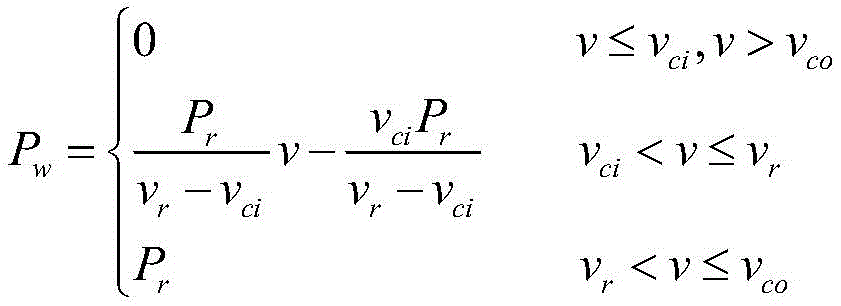
通过风力发电出力与模拟风速的关系对模拟风速进行计算,获得模拟风速对应的风力发电出力,风力发电出力与模拟风速的关系如下:Calculate the simulated wind speed through the relationship between the wind power output and the simulated wind speed, and obtain the wind power output corresponding to the simulated wind speed. The relationship between the wind power output and the simulated wind speed is as follows:
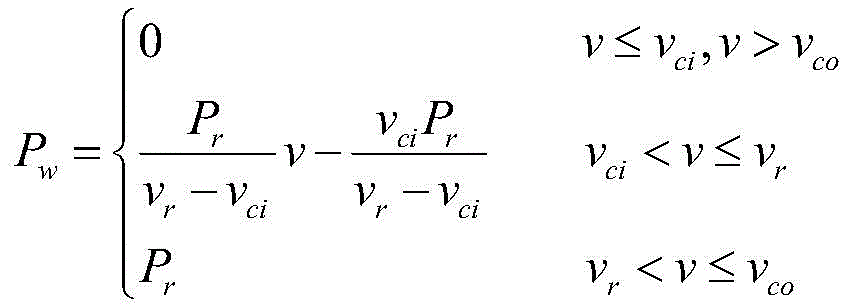
其中,Pw为风力发电出力;Pr为风机的额定出力;vci为切入风速;vco为切除风速;为额定风速。Among them, P w is the output of wind power generation; P r is the rated output of the fan; v ci is the cut-in wind speed; v co is the cut-off wind speed;
所述步骤3具体为:The
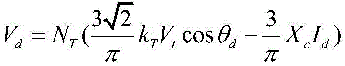
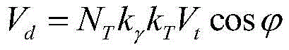
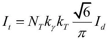
根据电力系统换流站中换流器的准稳态模型,按照下述公式建立含换流器的交直流耦合方程:According to the quasi-steady-state model of the converter in the power system converter station, the AC-DC coupling equation including the converter is established according to the following formula:


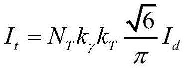
式中,Vt为电力系统中交流侧的电压;It为电力系统中交流侧的电流;Vd为电力系统中直流侧的电压;Id为电力系统中直流侧的电流;kT为直流侧和交流侧之间的换流变压器的变比;NT为换流器个数;Xc为换流器的等效阻抗;θd为换流时换流器设置的控制角;
所述步骤4具体为:The step 4 is specifically:
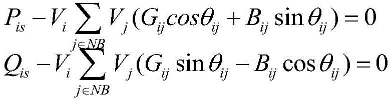
根据电力系统的交直流潮流方程获取换流器数量和功率之间的关系,利用换流器数量和功率之间的关系,通过以下公式获得各自换流器所在节点的功率平衡方程,对换流器所在节点的功率平衡方程进行建模,获得换流器所在节点的功率平衡方程模型;According to the AC/DC power flow equation of the power system, the relationship between the number of converters and power is obtained, and the relationship between the number of converters and power is used to obtain the power balance equation of the node where each converter is located by the following formula. Model the power balance equation of the node where the converter is located, and obtain the power balance equation model of the node where the converter is located;
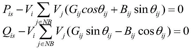
电力系统中换流器所在节点i处的功率平衡方程如下:The power balance equation at node i where the converter is located in the power system is as follows:


其中,Pis为节点i输入的有功功率;Qis为节点i输入的无功功率;Vi为节点i的电压;Vj为节点j的电压;NB为电力系统中节点的集合;Gij为线路ij导纳的实部;Bij为线路ij导纳的虚部;线路ij为节点i与节点j之间的连接线;θij为节点i与节点j之间的相角差;NT为换流器个数;Vd为电力系统中直流侧的电压;Id为电力系统中直流侧的电流,
所述步骤5具体为:The
利用含换流器的交直流耦合方程和换流器所在节点的节点功率平衡模型获得约束条件,建立满足约束条件的最优调度模型;最优调度模型在给定可变数据下,优化调度发电机组的出力和合理减少负荷的需求使得电力系统的发电代价和减少负荷代价总和最小,所述给定可变数据包括可用换流器数量、发电机组的可用情况、风力发电出力;The constraints are obtained by using the AC-DC coupling equation including the converter and the node power balance model of the node where the converter is located, and an optimal dispatching model that satisfies the constraints is established; the optimal dispatching model optimizes dispatching power generation under given variable data The output of the unit and the demand for reasonable load reduction minimize the sum of the power generation cost and the load reduction cost of the power system. The given variable data includes the number of available converters, the availability of the generator set, and the output of wind power generation;
最优调度模型的目标函数为电力系统的发电代价和减少负荷代价总和最小,公式如下:The objective function of the optimal dispatch model is the minimum sum of power generation cost and load reduction cost of the power system, the formula is as follows:

式中,TC为电力系统的发电代价和减少负荷代价总和;NG为电力系统中所有发电机组的集合;Cn()为发电机组n的发电代价函数;PG,n为发电机组n的有功出力;VOLL为电力系统的单位负荷减少对应的代价;ΔPlaod为电力系统的负荷减少的量;In the formula, TC is the sum of power generation cost and load reduction cost of the power system; NG is the set of all generating units in the power system; C n () is the generating cost function of generating unit n; PG,n is the active power of generating unit n Output; VOLL is the cost corresponding to the unit load reduction of the power system; ΔP laod is the amount of load reduction of the power system;
所述约束条件具体为节点能量平衡约束、节点电压约束、发电机组出力约束、负荷减少约束、线路潮流约束、直流变量约束和控制站控制方式约束;The constraints are specifically node energy balance constraints, node voltage constraints, generating unit output constraints, load reduction constraints, line power flow constraints, DC variable constraints, and control station control mode constraints;
1)节点能量平衡约束1) Node energy balance constraint
节点能量平衡约束包括换流器所在节点的功率平衡方程和纯交流节点的功率平衡方程,所述的纯交流节点为无换流站的节点,纯交流节点包括有发电机组的节点和普通节点;The node energy balance constraint includes the power balance equation of the node where the converter is located and the power balance equation of the pure AC node. The pure AC node is a node without a converter station, and the pure AC node includes a node with a generator set and a normal node;
其中换流器所在节点的功率平衡方程如下式所示:The power balance equation of the node where the converter is located is shown in the following formula:

其中,Pis节点i输入的有功功率;Qis为节点i输入的无功功率;Vi为节点i的电压;Vj为节点j的电压;NB为电力系统中节点的集合;Gij为线路ij的导纳的实部;Bij为线路ij导纳的虚部;线路ij为节点i与节点j之间的连接线;θij为节点与节点j之间的相角差;NT为换流器个数;Vd为电力系统中直流侧的电压;Id为电力系统中直流侧的电流;
纯交流节点的功率平衡方程如下式所示:The power balance equation of a pure AC node is as follows:
其中,Pis节点i输入的有功功率;Qis为节点i输入的无功功率;Vi为节点i的电压;Vj为节点j的电压;NB为电力系统中节点的集合;Gij为线路ij导纳的实部;Bij为线路ij导纳的虚部;线路ij为节点i与节点j之间的连接线;Among them, P is the active power input by node i; Q is the reactive power input by node i; V i is the voltage of node i; V j is the voltage of node j; NB is the set of nodes in the power system; G ij is The real part of the admittance of the line ij; B ij is the imaginary part of the admittance of the line ij; the line ij is the connecting line between the node i and the node j;
2)节点电压约束2) Node voltage constraints
Vmin≤Vi≤Vmax V min ≤ V i ≤ V max
其中,Vi为节点i的电压;Vmin为节点电压下限;Vmax为节点电压上限;Among them, V i is the voltage of node i; V min is the lower limit of node voltage; V max is the upper limit of node voltage;
3)发电机组出力约束3) Generator set output constraints
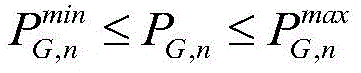

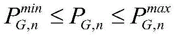
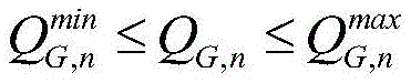
其中,PG,n发电机组n的有功出力;QG,n发电机组n的有功出力;为发电机组n的有功出力最小值;


4)负荷减少约束4) Load reduction constraints

其中:ΔPlaod为电力系统的负荷减少的量;
5)线路潮流约束5) Line flow constraints

其中,Vi为节点i的电压;Vj为节点j的电压;Gij为线路ij导纳的实部;线路ij为节点i与节点j之间的连接线;
6)直流变量约束6) DC variable constraints
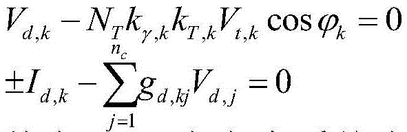
Vd,k-NT(kT,kVt,k cosθd,k-Xc,kId,k)=0V d,k -N T (k T,k V t,k cosθ d,k -X c,k I d,k )=0


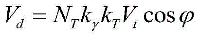
其中,Vd,k为电力系统中换流站k处的直流侧电压,NT为换流器个数,kT,k为换流站k处的换流变压器的变比;Vt,k为电力系统中换流站k处交流侧的电压;θd,k为换流站k处换流器设置的控制角;Xc,k为换流站k处换流器等效阻抗;Id,k为电力系统中换流站k处直流侧的电流;kγ,k为换流站k处换相效应系数;
7)换流站控制方式约束7) Constraints on the control mode of the converter station
Id,k-Icon,k=0I d,k -I con,k =0
cosθd,k-cosθcon,k=0cosθ d,k -cosθ con,k =0
其中,Icon,k为换流站k在定电流控制方式下设定的电流整定值;θcon,k为换流站k在定控制角控制方式下设定的控制角整定值。Among them, I con,k is the current setting value set by converter station k in the constant current control mode; θ con,k is the control angle setting value set by converter station k in the constant control angle control mode.
所述电力系统中换流站的个数小于发电机组的个数。The number of converter stations in the power system is smaller than the number of generator sets.
所述的可靠性参数包括换流器的可靠性参数和发电机组的可靠性参数。The reliability parameters include the reliability parameters of the converter and the reliability parameters of the generating set.
本发明的风力不确定性通过威布尔分布模拟得到,通过获取随机数的方法计算得到风电的出力情况,实现风电出力不确定性的模拟,另外使用换流器个数和发电机组可用情况作为条件计算最优调度模型,获取可靠性分析结果。The uncertainty of wind power in the present invention is obtained through Weibull distribution simulation, and the output of wind power is calculated by obtaining random numbers to realize the simulation of wind power output uncertainty. In addition, the number of converters and the availability of generator sets are used as conditions Calculate the optimal scheduling model and obtain reliability analysis results.
本发明的有益效果在于:The beneficial effects of the present invention are:
1)本发明采用威布尔分布模拟方法和基于换流器的交直流模型方法受电力数据的分布特点影响较小,能使用内点法有效收敛至最优解,获得稳定的分析结果。1) The present invention uses the Weibull distribution simulation method and the AC/DC model method based on the converter, which is less affected by the distribution characteristics of the power data, and can effectively converge to the optimal solution using the interior point method to obtain stable analysis results.
2)本发明同时考虑风力发电的不确定性和特高压直流的故障概率,对电力系统进行可靠性仿真分析,并针对分析结果进行有效的措施,从而能够达到提高电力系统的运行可靠性目的。2) The present invention simultaneously considers the uncertainty of wind power generation and the failure probability of UHV DC, performs reliability simulation analysis on the power system, and takes effective measures for the analysis results, so as to achieve the purpose of improving the operation reliability of the power system.
附图说明Description of drawings
图1是本发明的技术方案流程图;Fig. 1 is a technical scheme flowchart of the present invention;
图2是本发明-实施例的24节点电力系统的拓扑结构图;Fig. 2 is the topological structure diagram of the 24-node power system of the present invention-embodiment;
图3是本发明实施例5个场景的可靠性分析判断结果。Fig. 3 is the reliability analysis and judgment results of five scenarios in the embodiment of the present invention.
具体实施方式Detailed ways
下面结合实施例及其附图对本发明方法作进一步的说明。The method of the present invention will be further described below in conjunction with the embodiments and accompanying drawings.
本发明的实施例及其实施过程如下:Embodiments of the present invention and its implementation process are as follows:
特高压指的是直流电压±800kV和交流电压1000kV以上的电压。UHV refers to the voltage above ±800kV DC and 1000kV AC.
如图1所示,步骤1:根据大多数地区的风速分布具有一定规律,利用威布尔分布模型模拟风速的累计概率分布;As shown in Figure 1, step 1: According to the fact that the wind speed distribution in most areas has certain rules, the cumulative probability distribution of wind speed is simulated by using the Weibull distribution model;
威布尔分布模型模拟风速的累计概率分布,公式如下:The Weibull distribution model simulates the cumulative probability distribution of wind speed, the formula is as follows:
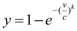
式中,v为模拟风速,c为尺度参数,k为形状参数,y表示出现模拟风速v时对应的概率,y满足0≤y≤1。模拟风速v为变量值,c和k为确定的已知参数。In the formula, v is the simulated wind speed, c is the scale parameter, k is the shape parameter, y represents the corresponding probability when the simulated wind speed v occurs, and y satisfies 0≤y≤1. The simulated wind speed v is a variable value, and c and k are certain known parameters.
步骤2:对风速的累计概率分布进行处理得到获得模拟风速,通过风力发电出力与模拟风速的关系对模拟风速进行计算获得风力发电出力,实现风力发电出力的不确定性模拟;Step 2: Process the cumulative probability distribution of wind speed to obtain simulated wind speed, calculate the simulated wind speed through the relationship between wind power output and simulated wind speed to obtain wind power output, and realize the uncertainty simulation of wind power output;
将风速的累计概率分布进行处理得到威布尔分布的风速,对威布尔分布的风速随机取值后获得模拟风速,公式如下:The cumulative probability distribution of wind speed is processed to obtain the wind speed of Weibull distribution, and the wind speed of Weibull distribution is randomly selected to obtain the simulated wind speed. The formula is as follows:

上述公式为对公式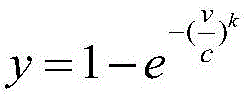
通过风力发电出力与模拟风速的关系对模拟风速进行计算,获得模拟风速对应的风力发电出力,风力发电出力与模拟风速的关系,即风力发电的出力特性函数如下:The simulated wind speed is calculated through the relationship between the wind power output and the simulated wind speed, and the wind power output corresponding to the simulated wind speed is obtained. The relationship between the wind power output and the simulated wind speed, that is, the output characteristic function of wind power is as follows:

其中,Pw为风力发电出力;Pr为风机的额定出力;vci为切入风速;vco为切除风速;vr为额定风速。Among them, P w is the output of wind power generation; P r is the rated output of the fan; v ci is the cut-in wind speed; v co is the cut-off wind speed; v r is the rated wind speed.
步骤3:根据电力系统的换流站中换流器的准稳态模型,获得含换流器的交直流耦合方程;Step 3: According to the quasi-steady-state model of the converter in the converter station of the power system, obtain the AC-DC coupling equation including the converter;
根据电力系统换流站中换流器的准稳态模型,按照下述公式建立含换流器的交直流耦合方程:According to the quasi-steady-state model of the converter in the power system converter station, the AC-DC coupling equation including the converter is established according to the following formula:


式中,Vt为电力系统中交流侧的电压;It为电力系统中交流侧的电流;Vd为电力系统中直流侧的电压;Id为电力系统中直流侧的电流;kT为直流侧和交流侧之间的换流变压器的变比;NT为换流器个数;Xc为换流器的等效阻抗;θd为换流时换流器设置的控制角;
步骤4:根据电力系统的交直流潮流方程获取换流器数量和功率的关系,获得各自换流器所在节点的功率平衡方程,确定换流器所在节点的节点功率平衡模型;Step 4: Obtain the relationship between the number of converters and power according to the AC and DC power flow equations of the power system, obtain the power balance equations of the nodes where the respective converters are located, and determine the node power balance model of the nodes where the converters are located;
根据电力系统的交直流潮流方程获取换流器数量和功率之间的关系,利用换流器数量和功率之间的关系,通过以下公式获得换流器所在节点的功率平衡方程,换流站包括多个换流器,即换流器所在节点为换流站所在节点,电力系统是由节点构成,节点是电力系统中支路之间的连接点,风力发电机组、换流站和发电机组均在节点上,对换流器所在节点的功率平衡方程进行建模,获得换流器所在节点的功率平衡方程模型;According to the AC/DC power flow equation of the power system, the relationship between the number of converters and the power is obtained. Using the relationship between the number of converters and the power, the power balance equation of the node where the converter is located is obtained by the following formula. The converter station includes Multiple converters, that is, the node where the converter is located is the node where the converter station is located, the power system is composed of nodes, and the node is the connection point between branches in the power system. On the node, model the power balance equation of the node where the converter is located, and obtain the power balance equation model of the node where the converter is located;
电力系统中换流器所在节点i处的功率平衡方程如下:The power balance equation at node i where the converter is located in the power system is as follows:

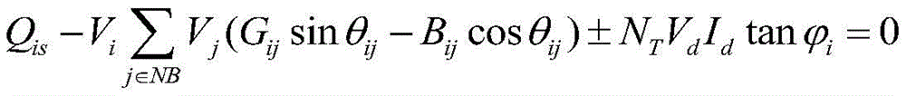
其中,Pis为节点i输入的有功功率;Qis为节点i输入的无功功率;Vi为节点i的电压;Vj为节点j的电压;NB为电力系统中节点的集合;Gij为线路ij导纳的实部;Bij为线路ij导纳的虚部;线路ij为节点i与节点j之间的连接线;θij为节点i与节点j之间的相角差;NT为换流器个数;Vd为电力系统中直流侧的电压;Id为电力系统中直流侧的电流,
步骤5:利用含换流器的交直流耦合方程和换流器所在节点的节点功率平衡模型,建立最优调度模型;Step 5: Using the AC-DC coupling equation including the converter and the node power balance model of the node where the converter is located, an optimal dispatching model is established;
利用含换流器的交直流耦合方程和换流器所在节点的节点功率平衡模型获得约束条件,建立满足约束条件的最优调度模型;最优调度模型在给定可变数据下,优化调度发电机组的出力和合理减少负荷的需求使得电力系统的发电代价和减少负荷代价总和最小,所述给定可变数据包括可用换流器数量、发电机组的可用情况、风力发电出力;The constraints are obtained by using the AC-DC coupling equation including the converter and the node power balance model of the node where the converter is located, and an optimal dispatching model that satisfies the constraints is established; the optimal dispatching model optimizes dispatching power generation under given variable data The output of the unit and the demand for reasonable load reduction minimize the sum of the power generation cost and the load reduction cost of the power system. The given variable data includes the number of available converters, the availability of the generator set, and the output of wind power generation;
最优调度模型的目标函数为电力系统的发电代价和减少负荷代价总和最小,公式如下:The objective function of the optimal dispatch model is the minimum sum of power generation cost and load reduction cost of the power system, the formula is as follows:

式中,TC为电力系统的发电代价和减少负荷代价总和;NG为电力系统中所有发电机组的集合;Cn()为发电机组n的发电代价函数;PG,n为发电机组n的有功出力;VOLL为电力系统的单位负荷减少对应的代价;ΔPlaod为电力系统的负荷减少的量;In the formula, TC is the sum of power generation cost and load reduction cost of the power system; NG is the set of all generating units in the power system; C n () is the generating cost function of generating unit n; PG,n is the active power of generating unit n Output; VOLL is the cost corresponding to the unit load reduction of the power system; ΔP laod is the amount of load reduction of the power system;
约束条件具体为节点能量平衡约束、节点电压约束、发电机组出力约束、负荷减少约束、线路潮流约束、直流变量约束和控制站控制方式约束;Constraint conditions specifically include node energy balance constraints, node voltage constraints, generating unit output constraints, load reduction constraints, line power flow constraints, DC variable constraints, and control station control mode constraints;
1)节点能量平衡约束1) Node energy balance constraint
节点能量平衡约束包括换流器所在节点的功率平衡方程和纯交流节点的功率平衡方程,纯交流节点为无换流站的节点,纯交流节点包括有发电机组的节点和普通节点;Node energy balance constraints include the power balance equation of the node where the converter is located and the power balance equation of the pure AC node. The pure AC node is a node without a converter station, and the pure AC node includes a node with a generator set and a normal node;
其中换流器所在节点的功率平衡方程如下式所示:The power balance equation of the node where the converter is located is shown in the following formula:


其中,Pis节点i输入的有功功率;Qis为节点i输入的无功功率;Vi为节点i的电压;Vj为节点j的电压;NB为电力系统中节点的集合;Gij为线路ij的导纳的实部;Bij为线路ij导纳的虚部;线路ij为节点i与节点j之间的连接线;θij为节点i与节点j之间的相角差;NT为换流器个数;Vd为电力系统中直流侧的电压;Id为电力系统中直流侧的电流;
纯交流节点的功率平衡方程如下式所示:The power balance equation of a pure AC node is as follows:

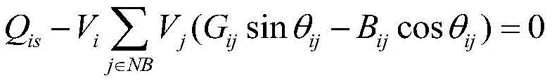
其中,Pis节点i输入的有功功率;Qis为节点i输入的无功功率;Vi为节点i的电压;Vj为节点j的电压;NB为电力系统中节点的集合;Gij为线路ij导纳的实部;Bij为线路ij导纳的虚部;线路ij为节点i与节点j之间的连接线;Among them, P is the active power input by node i; Q is the reactive power input by node i; V i is the voltage of node i; V j is the voltage of node j; NB is the set of nodes in the power system; G ij is The real part of the admittance of the line ij; B ij is the imaginary part of the admittance of the line ij; the line ij is the connecting line between the node i and the node j;
2)节点电压约束2) Node voltage constraints
Vmin≤Vi≤Vmax V min ≤ V i ≤ V max
其中:Vi为节点i的电压;Vmin为节点电压下限;Vmax为节点电压上限。Among them: V i is the voltage of node i; V min is the lower limit of node voltage; V max is the upper limit of node voltage.
3)发电机组出力约束3) Generator set output constraints
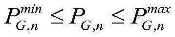

其中:PG,n发电机组n的有功出力;QG,n发电机组n的有功出力;


4)减少负荷约束4) Reduce load constraints

其中:ΔPlaod为电力系统的负荷减少的值;
5)线路潮流约束5) Line flow constraints

其中,Vi为节点i的电压;Vj为节点j的电压;Gij为线路ij导纳的实部;线路ij为节点i与节点j之间的连接线;

6)直流变量约束6) DC variable constraints
Vd,k-NT(kT,kVt,k cosθd,k-Xc,kId,k)=0V d,k -N T (k T,k V t,k cosθ d,k -X c,k I d,k )=0


其中,Vd,k为电力系统中换流站k处的直流侧电压,NT为换流器个数,kT,k为换流站k处的换流变压器的变比;Vt,k为电力系统中换流站k处交流侧的电压;θd,k为换流站k处换流器设置的控制角;Xc,k为换流站k处换流器等效阻抗;Id,k为电力系统中换流站k处直流侧的电流;kγ,k为换流站k处换相效应系数;
7)换流站控制方式约束7) Constraints on the control mode of the converter station
Id,k-Icon,k=0I d,k -I con,k =0
cosθd,k-cosθcon,k=0cosθ d,k -cosθ con,k =0
其中,Icon,k为换流站k在定电流控制方式下设定的电流整定值;θcon,k为换流站k在定控制角控制方式下设定的控制角整定值。Among them, I con,k is the current setting value set by converter station k in the constant current control mode; θ con,k is the control angle setting value set by converter station k in the constant control angle control mode.
步骤6:根据电力系统的可靠性参数随机模拟可用换流器的个数和发电机组可用情况,向最优调度模型输入风力发电出力,最优调度模型根据可用换流器的个数、发电机组可用情况、风力发电大小对优化调度模型进行求解,求解后获得优化调度之后负荷减少的量ΔPlaod,并根据负荷减少的量ΔPlaod计算供电不足电量EENS,基于供电不足电量EENS进行提高电力系统的可靠性。Step 6: Randomly simulate the number of available converters and the availability of generating units according to the reliability parameters of the power system, and input the output of wind power generation into the optimal dispatching model. The optimal scheduling model is solved based on the available situation and the size of wind power generation. After the solution, the load reduction ΔP laod after optimal scheduling is obtained, and the insufficient power supply EENS is calculated according to the load reduction ΔP laod , and the power system is improved based on the insufficient power supply EENS reliability.
具体是首先基于步骤1和步骤2风力出力的获取方式模拟风力发电的不确定性出力。Specifically, the uncertain output of wind power generation is firstly simulated based on the acquisition methods of wind power output in
然后通过可靠性参数随机模拟可用换流器的个数,可靠性参数包括换流器的可靠性参数和发电机组的可靠性参数,以最多4个换流器为例,可用换流器计算方法如下:Then, the number of available converters is randomly simulated through the reliability parameters. The reliability parameters include the reliability parameters of the converters and the reliability parameters of the generator set. Taking a maximum of 4 converters as an example, the available converter calculation method as follows:

其中,NT为换流器的个数,其由随机模拟量x确定,并且随机模拟量x在[0,1]范围中随机取值;a,b,c,d即是换流器的可靠性参数。Among them, N T is the number of converters, which is determined by the random analog x, and the random analog x takes a random value in the range [0, 1]; a, b, c, d are the converters Reliability parameters.
然后,发电机组是否可用由发电机组的可靠性参数随机模拟得到,其计算方法如下:Then, whether the generating set is available is obtained by random simulation of the reliability parameters of the generating set, and its calculation method is as follows:

其中,S为发电机组可用情况,如果S为1,则发电机组能够有效调度使用,如果S为0,该发电机组将不可用,优化调度模型中将不包含该发电机组;发电机组可用情况其由随机自变量z确定,并且随机自变量z在[0,1]范围中随机取值;FOR为发电机组的可靠性参数。Among them, S is the availability of the generator set. If S is 1, the generator set can be effectively dispatched and used. If S is 0, the generator set will not be available, and the optimal scheduling model will not include the generator set; It is determined by the random independent variable z, and the random independent variable z takes a random value in the range of [0, 1]; FOR is the reliability parameter of the generating set.
最后,在获得风力发电出力、可用换流器个数和发电机组可用情况之后,将上述值代入步骤5中最优调度模型并求解,得到电力系统负荷减少的量ΔPlaod,基于负荷减少的量ΔPlaod对供电不足电量EENS进行计算,供电不足电量EENS计算方法如下:Finally, after obtaining the output of wind power generation, the number of available converters and the availability of generator sets, the above values are substituted into the optimal dispatching model in
EENS=ΔPload·8760EENS=ΔP load 8760
基于供电不足电量EENS进行提高电力系统的可靠性。Improve the reliability of the power system based on the insufficient power supply EENS.
根据供电不足电量EENS进行提高电力系统的可靠性,具体为:Improve the reliability of the power system according to the insufficient power supply EENS, specifically:
若供电不足电量EENS大于运行需求的设定值,则电力系统的可靠性未达到预期,可以采用修改风力发电接入比例和特高压直流接入比例的方法改善电力系统的可靠性;If the insufficient power supply EENS is greater than the set value of the operation demand, the reliability of the power system has not met expectations, and the method of modifying the proportion of wind power generation and UHV DC connection can be used to improve the reliability of the power system;
若供电不足电量EENS小于运行需求的设定值,则电力系统的可靠性达到预期,不作任何处理。If the insufficient power supply EENS is less than the set value of the operation demand, the reliability of the power system meets expectations and no processing is performed.
实施例Example
本发明对24节点电力系统进行可靠性情况分析判断,24节点的拓扑结构如图2所示,其中节点17含有换流站,节点18、21、22等含有发电机组,节点1、16、和23含有风力发电机组。电力系统的原始负荷量为2500MW;威布尔分布尺度参数c,形状参数k分别为7和2;切入风速、切除风速和额定风速为3m/s,20m/s,13.5m/s。最多可用换流器个数为4个;选用供电不足电量作为可靠性分析指标(该值越小越好);选取5个不同的场景对可靠性进行分析。不同比例特高压直流接入容量和风力发电接入容量情况如表1所示:The present invention analyzes and judges the reliability of a 24-node power system. The topological structure of the 24 nodes is shown in Figure 2, wherein


上述5个场景的可靠性分析结果如图3所示。The reliability analysis results of the above five scenarios are shown in Figure 3.
由图3可知,场景1中,即是特高压直流和风力发电比例较低时,电力系统可靠性较好;随着特高压直流和风力发电的比例增加时,电力系统的供电不足电量越来越高;在场景4中,特高压直流和风力发电的比例最高,供电不足电量也达到最大,说明此时电力系统可靠性较差,需要采取对应措施提高可靠性。It can be seen from Figure 3 that in
由图3可知,本发明方法能够有效对特高压直流和出力不确定的风电接入的电力系统进行可靠性分析,根据供电不足电量EENS进行提高电力系统的可靠性,具体为:It can be seen from Figure 3 that the method of the present invention can effectively analyze the reliability of the power system connected to UHV DC and wind power with uncertain output, and improve the reliability of the power system according to the insufficient power supply EENS, specifically:
若供电不足电量EENS大于运行需求的设定值,则电力系统的可靠性未达到预期,可以采用修改风力发电接入比例和特高压直流接入比例的方法改善电力系统的可靠性;If the insufficient power supply EENS is greater than the set value of the operation demand, the reliability of the power system has not met expectations, and the method of modifying the proportion of wind power generation and UHV DC connection can be used to improve the reliability of the power system;
若供电不足电量EENS小于运行需求的设定值,则电力系统的可靠性达到预期,不作任何处理。由此帮助电力系统合理设置特高压直流接入量和风力发电的接入量,保证电力系统的可靠运行。If the insufficient power supply EENS is less than the set value of the operation demand, the reliability of the power system meets expectations and no processing is performed. This helps the power system to reasonably set the UHV DC access and wind power access to ensure reliable operation of the power system.
Claims (7)


Priority Applications (1)
| Application Number | Priority Date | Filing Date | Title |
|---|---|---|---|
| CN202011561272.0A CN112803473B (en) | 2020-12-25 | 2020-12-25 | Method for improving reliability of extra-high voltage direct current access power system with uncertain wind power |
Applications Claiming Priority (1)
| Application Number | Priority Date | Filing Date | Title |
|---|---|---|---|
| CN202011561272.0A CN112803473B (en) | 2020-12-25 | 2020-12-25 | Method for improving reliability of extra-high voltage direct current access power system with uncertain wind power |
Publications (2)
| Publication Number | Publication Date |
|---|---|
| CN112803473A CN112803473A (en) | 2021-05-14 |
| CN112803473B true CN112803473B (en) | 2022-11-29 |
Family
ID=75804954
Family Applications (1)
| Application Number | Title | Priority Date | Filing Date |
|---|---|---|---|
| CN202011561272.0A Active CN112803473B (en) | 2020-12-25 | 2020-12-25 | Method for improving reliability of extra-high voltage direct current access power system with uncertain wind power |
Country Status (1)
| Country | Link |
|---|---|
| CN (1) | CN112803473B (en) |
Family Cites Families (7)
| Publication number | Priority date | Publication date | Assignee | Title |
|---|---|---|---|---|
| CN102545201B (en) * | 2011-12-27 | 2014-11-19 | 上海交通大学 | A Method for Establishing Small-Signal Model of HVDC Transmission |
| CN106877336B (en) * | 2017-03-14 | 2020-01-10 | 长沙理工大学 | Continuous power flow method of alternating current-direct current power system considering wind power randomness |
| CN108808680A (en) * | 2017-04-27 | 2018-11-13 | 华北电力大学(保定) | A kind of interregional ability to transmit electricity computational methods of wind fire bundling alternating current-direct current delivery system |
| CN108808725B (en) * | 2017-05-05 | 2023-03-21 | 通用电气公司 | System and method for reactive power control of wind farm |
| CN108565865B (en) * | 2018-05-02 | 2020-12-29 | 浙江大学 | A risk assessment method for an AC-DC hybrid system with wind power |
| CN108879664B (en) * | 2018-06-29 | 2020-08-04 | 国网山东省电力公司电力科学研究院 | AC/DC system online voltage stability evaluation method based on wide area measurement |
| CN108964061B (en) * | 2018-07-23 | 2021-10-08 | 长沙理工大学 | A probabilistic dynamic continuous power flow calculation method for AC and DC power systems with wind power considering the static characteristics of load frequency and voltage |
-
2020
- 2020-12-25 CN CN202011561272.0A patent/CN112803473B/en active Active
Also Published As
| Publication number | Publication date |
|---|---|
| CN112803473A (en) | 2021-05-14 |
Similar Documents
| Publication | Publication Date | Title |
|---|---|---|
| CN103633657B (en) | A kind of method that wind electricity storage station network load peak regulation and wind-powered electricity generation fluctuation suppress and device | |
| CN106340897B (en) | A kind of determination method of power distribution network distributed generation resource allowed capacity | |
| CN103904673B (en) | A Method for Optimizing PI Parameters of Constant Current Controller for HVDC Transmission | |
| CN113300353B (en) | A method and device for calculating power grid partition load margin considering N-1 reliability | |
| CN103762579A (en) | Direct-current power emergency control performance index calculation method for improving transient power angle stability of power grid | |
| CN114491886A (en) | General modeling method and device for active power distribution network containing multi-type distributed new energy | |
| CN114330521A (en) | Secondary grouping method and device for wind power plant units and storage medium thereof | |
| CN116780638A (en) | Snowflake distribution network operation optimization method and device including soft switching and distributed energy storage | |
| CN113224788B (en) | Static voltage stability evaluation method for AC/DC hybrid power grid with wind power access | |
| CN108629499A (en) | A kind of power distribution network photovoltaic plant addressing constant volume method based on second order cone theazy | |
| CN112347595B (en) | A frequency elasticity assessment method for multi-DC feed-in receiving-end power grid | |
| CN116611011A (en) | Transient overvoltage amplitude prediction method, system, terminal and medium | |
| CN115733133A (en) | A simulation method and system for a load model based on distributed electrochemical energy storage | |
| CN105279297B (en) | A kind of PSS/E electric system equivalence methods based on engineer application | |
| CN112803473B (en) | Method for improving reliability of extra-high voltage direct current access power system with uncertain wind power | |
| CN116667402A (en) | Method and system for parameter identification of grid-connected transient simulation model for electrochemical energy storage system | |
| Rudion et al. | MaWind-tool for the aggregation of wind farm models | |
| CN118971016B (en) | Multi-converter aggregation method based on capacity weighting | |
| CN112329231A (en) | Voltage elastic force evaluation method suitable for alternating current-direct current series-parallel connection receiving end power grid | |
| CN110096767B (en) | Cascading failure simulation method for alternating current-direct current series-parallel power grid | |
| CN116581757B (en) | Load model modeling method and system considering high-proportion power electronic equipment | |
| CN114006415B (en) | A method, system and medium for evaluating the improvement of distribution network's new energy acceptance capacity | |
| CN107562971B (en) | Alternating current/direct current power grid power flow calculation method based on PSS/E | |
| CN116470522A (en) | A control parameter identification method and device for an SVG general electromagnetic transient model | |
| CN110518633B (en) | Power grid node new energy admission capacity obtaining method considering line capacity adequacy |
Legal Events
| Date | Code | Title | Description |
|---|---|---|---|
| PB01 | Publication | ||
| PB01 | Publication | ||
| SE01 | Entry into force of request for substantive examination | ||
| SE01 | Entry into force of request for substantive examination | ||
| GR01 | Patent grant | ||
| GR01 | Patent grant |