CN112809727B - A rope traction rigid-flexible coupling variable stiffness gripper - Google Patents
A rope traction rigid-flexible coupling variable stiffness gripper Download PDFInfo
- Publication number
- CN112809727B CN112809727B CN202110105280.2A CN202110105280A CN112809727B CN 112809727 B CN112809727 B CN 112809727B CN 202110105280 A CN202110105280 A CN 202110105280A CN 112809727 B CN112809727 B CN 112809727B
- Authority
- CN
- China
- Prior art keywords
- flexible
- rigid
- clamping assembly
- finger
- assembly
- Prior art date
- Legal status (The legal status is an assumption and is not a legal conclusion. Google has not performed a legal analysis and makes no representation as to the accuracy of the status listed.)
- Active
Links
- 230000008878 coupling Effects 0.000 title claims abstract description 24
- 238000010168 coupling process Methods 0.000 title claims abstract description 24
- 238000005859 coupling reaction Methods 0.000 title claims abstract description 24
- 230000007246 mechanism Effects 0.000 claims abstract description 30
- 210000002435 tendon Anatomy 0.000 claims description 17
- 230000005540 biological transmission Effects 0.000 claims description 8
- 229920001971 elastomer Polymers 0.000 claims description 5
- 230000033001 locomotion Effects 0.000 claims description 5
- 238000004804 winding Methods 0.000 description 37
- 239000000463 material Substances 0.000 description 9
- 238000004519 manufacturing process Methods 0.000 description 6
- 238000010586 diagram Methods 0.000 description 4
- 239000013013 elastic material Substances 0.000 description 3
- 239000004743 Polypropylene Substances 0.000 description 2
- 230000009286 beneficial effect Effects 0.000 description 2
- 238000012423 maintenance Methods 0.000 description 2
- 238000000034 method Methods 0.000 description 2
- 229910052755 nonmetal Inorganic materials 0.000 description 2
- 229910021420 polycrystalline silicon Inorganic materials 0.000 description 2
- -1 polypropylene Polymers 0.000 description 2
- 229920001155 polypropylene Polymers 0.000 description 2
- 229920005591 polysilicon Polymers 0.000 description 2
- 230000003044 adaptive effect Effects 0.000 description 1
- 230000000712 assembly Effects 0.000 description 1
- 238000000429 assembly Methods 0.000 description 1
- 230000008859 change Effects 0.000 description 1
- 230000007812 deficiency Effects 0.000 description 1
- 238000013461 design Methods 0.000 description 1
- 239000012636 effector Substances 0.000 description 1
- 210000004905 finger nail Anatomy 0.000 description 1
- 230000003993 interaction Effects 0.000 description 1
- 238000012986 modification Methods 0.000 description 1
- 230000004048 modification Effects 0.000 description 1
- 230000008569 process Effects 0.000 description 1
- 238000011160 research Methods 0.000 description 1
- 230000007480 spreading Effects 0.000 description 1
- 238000006467 substitution reaction Methods 0.000 description 1
Images


Classifications
-
- B—PERFORMING OPERATIONS; TRANSPORTING
- B25—HAND TOOLS; PORTABLE POWER-DRIVEN TOOLS; MANIPULATORS
- B25J—MANIPULATORS; CHAMBERS PROVIDED WITH MANIPULATION DEVICES
- B25J15/00—Gripping heads and other end effectors
- B25J15/08—Gripping heads and other end effectors having finger members
Landscapes
- Engineering & Computer Science (AREA)
- Robotics (AREA)
- Mechanical Engineering (AREA)
- Manipulator (AREA)
Abstract
Description
技术领域technical field
本发明涉及变刚度夹持器技术领域,更具体地说,涉及一种绳牵引刚柔耦合变刚度夹持器。The invention relates to the technical field of variable stiffness grippers, and more particularly, to a rope traction rigid-flexible coupling variable stiffness gripper.
背景技术Background technique
变刚度夹持器是指对夹持器自身刚度的控制,可以在不同的操作环境下,通过改变自身刚度从而实现对不同复杂、易碎物体的夹取操作,一定程度上弥补传统夹持器刚度过大以及软体夹持器由于自身柔软性高而刚度和抓取力不足的问题,具有较好的安全性和适应性。因此,其广泛应用于主要以结构学、智能材料为研究基础的智能制造以及工业机器人等领域。The variable stiffness gripper refers to the control of the stiffness of the gripper itself. It can realize the gripping operation of different complex and fragile objects by changing its own stiffness in different operating environments, making up for the traditional gripper to a certain extent. The problems of excessive rigidity and insufficient rigidity and grasping force of the soft gripper due to its high flexibility have better safety and adaptability. Therefore, it is widely used in the fields of intelligent manufacturing and industrial robots mainly based on structure and intelligent materials.
在工业以及日常生活的夹取任务中,一方面常需要机械臂的末端执行器对易碎物体进行稳定、自适应、变刚度的抓取操作,以实现尺寸复杂、形状不同的多抓取对象的安全抓取;另一方面,常需要将末端夹持器的尺寸模拟人手并运用绳索牵引作为驱动,在抓取过程中能够满足轻巧、灵活以及成本低的要求,以实现通用性、经济性和多夹持模式的夹取操作。由于上述两方面原因,同时实现变刚度、仿人手以及绳索欠驱动是工业机器人与智能制造领域的研究热点。In the gripping tasks of industry and daily life, on the one hand, the end effector of the robotic arm is often required to perform stable, adaptive and variable stiffness gripping operations on fragile objects, so as to achieve multiple gripping objects with complex sizes and different shapes. On the other hand, it is often necessary to simulate the size of the end gripper and use rope traction as the drive, which can meet the requirements of lightness, flexibility and low cost during the grasping process, so as to achieve versatility and economy. and multi-grip mode gripping operations. Due to the above two reasons, the simultaneous realization of variable stiffness, human-like hand and rope underactuation is a research hotspot in the field of industrial robots and intelligent manufacturing.
发明内容SUMMARY OF THE INVENTION
本发明的目的在于克服现有技术中的缺点与不足,提供一种绳牵引刚柔耦合变刚度夹持器,该夹持器具有变刚度的夹持能力,从而实现灵活、安全夹取物体;同时,该夹持器具有尺寸小、结构简单、成本低等优点,以较少的驱动器驱动夹持器关节自由度,有利于对尺寸复杂、形状不同的多抓取对象进行安全抓取的实现,适合应用于工业机器人与智能制造等领域。The purpose of the present invention is to overcome the shortcomings and deficiencies in the prior art, and provide a rope traction rigid-flexible coupling variable stiffness gripper, the gripper has the gripping ability of variable stiffness, thereby realizing flexible and safe gripping of objects; At the same time, the gripper has the advantages of small size, simple structure, low cost, etc., and uses fewer drivers to drive the freedom of the gripper joints, which is conducive to the realization of safe grasping of multiple grasping objects with complex sizes and different shapes , suitable for industrial robots and intelligent manufacturing and other fields.
为了达到上述目的,本发明通过下述技术方案予以实现:一种绳牵引刚柔耦合变刚度夹持器,其特征在于:包括内侧柔性机构、外侧刚性抓取机构和驱动电机;所述内侧柔性机构由对称设置的柔性左夹持组件与柔性右夹持组件通过连接件连接组成;所述外侧刚性抓取机构包括左驱动组件、右驱动组件、底座以及对称设置的刚性左夹持组件与刚性右夹持组件;所述柔性左夹持组件与柔性右夹持组件通过连接件与底座连接;所述刚性左夹持组件的一端与柔性左夹持组件连接,另一端与底座铰接;所述刚性右夹持组件的一端与柔性右夹持组件连接,另一端与底座铰接;所述左驱动组件和右驱动组件分别设置在刚性左夹持组件和刚性右夹持组件内部并与驱动电机连接,实现驱动电机通过左驱动组件和右驱动组件驱动刚性左夹持组件和刚性右夹持组件进行夹持或张开运动。In order to achieve the above purpose, the present invention is achieved through the following technical solutions: a rope traction rigid-flexible coupling variable rigidity gripper, which is characterized in that: it includes an inner flexible mechanism, an outer rigid grabbing mechanism and a drive motor; the inner flexible The mechanism is composed of symmetrically arranged flexible left clamping components and flexible right clamping components connected by connecting pieces; the outer rigid grasping mechanism includes a left driving component, a right driving component, a base, and symmetrically arranged rigid left clamping components and rigid a right clamping assembly; the flexible left clamping assembly and the flexible right clamping assembly are connected with the base through a connecting piece; one end of the rigid left clamping assembly is connected with the flexible left clamping assembly, and the other end is hinged with the base; the One end of the rigid right clamping component is connected with the flexible right clamping component, and the other end is hinged with the base; the left driving component and the right driving component are respectively arranged inside the rigid left clamping component and the rigid right clamping component and are connected with the driving motor , to realize that the driving motor drives the rigid left clamping assembly and the rigid right clamping assembly to perform clamping or opening movement through the left driving assembly and the right driving assembly.
所述柔性左夹持组件与柔性右夹持组件结构相同,均包括依次连接的顶端夹持杆、第一双面柔性转动副、柔性夹持杆和第二双面柔性转动副;所述柔性左夹持组件与柔性右夹持组件均通过第二双面柔性转动副与连接件连接。The flexible left clamping assembly has the same structure as the flexible right clamping assembly, and includes a top clamping rod, a first double-sided flexible rotating pair, a flexible clamping rod and a second double-sided flexible rotating pair that are connected in sequence; the flexible Both the left clamping component and the flexible right clamping component are connected with the connecting piece through the second double-sided flexible rotating pair.
所述第一双面柔性转动副和第二双面柔性转动副均为正圆型双面柔性转动副。本发明采用的正圆型双面柔性转动副的主要特征是:结构简单、易于制造、不需要组装与维护、没有摩擦损失,表现在拓扑结构与其对应的刚度机构类似,多集中柔度型柔性运动副代替传统运动副。The first double-sided flexible rotating pair and the second double-sided flexible rotating pair are both perfect circular double-sided flexible rotating pairs. The main features of the perfect circular double-sided flexible rotating pair used in the present invention are: simple structure, easy to manufacture, no need for assembly and maintenance, no friction loss, and the topological structure is similar to its corresponding rigidity mechanism, and the multi-concentrated flexibility type is flexible. The kinematic pair replaces the traditional kinematic pair.
所述顶端夹持杆的表面设置用于增大摩擦力的齿状结构。The surface of the top clamping rod is provided with a tooth-like structure for increasing the frictional force.
所述内侧柔性机构为一体成型的橡胶构件。该内侧柔性机构的材料选择的基本原则:其一,主要考虑其强度极限与弹性模量之比。如:聚丙烯、多晶硅、橡胶等为理想的非金属弹性材料。其二,充分考虑材料的抗疲劳指标。确保材料在变形时不会发生张力松弛或蠕变。其三,在以上两点都满足的情况下,考虑材料的经济适用性。The inner flexible mechanism is an integrally formed rubber member. The basic principles of material selection of the inner flexible mechanism: First, the ratio of its strength limit and elastic modulus is mainly considered. Such as: polypropylene, polysilicon, rubber, etc. are ideal non-metal elastic materials. Second, fully consider the fatigue resistance of the material. Ensure that the material does not experience tension relaxation or creep when deforming. Third, in the case of satisfying the above two points, consider the economical applicability of the material.
所述刚性左夹持组件与刚性右夹持组件结构相同,均包括依次铰接的末指和根指;所述刚性左夹持组件通过末指与柔性左夹持组件铰接,并通过根指与底座铰接;所述刚性右夹持组件通过末指与柔性右夹持组件铰接,并通过根指与底座铰接。The rigid left clamping assembly has the same structure as the rigid right clamping assembly, and both include a last finger and a root finger that are hinged in sequence; the rigid left clamping assembly is hinged with the flexible left clamping assembly through the last finger, and is connected to the flexible left clamping assembly through the root finger. The base is hinged; the rigid right clamping component is hinged with the flexible right clamping component through the last finger, and is hinged with the base through the root finger.
所述左驱动组件和右驱动组件结构相同,均包括设置在末指和根指内腔的弹性牵引装置和传动装置;所述传动装置圈绕弹性牵引装置并穿出底座与驱动电机连接。The left drive assembly and the right drive assembly have the same structure, and both include elastic traction devices and transmission devices arranged in the inner cavity of the last finger and the root finger;
所述弹性牵引装置包括拉伸回弹弹簧和扭簧;所述扭簧设置在根指与底座的铰接链处;所述拉伸回弹弹簧一端固定在末指上,另一端依次绕过末指与根指的铰接链以及根指与底座的铰接链,最后固定于连接件与底座的连接处,形成夹持器的伸肌腱结构。The elastic traction device includes a stretched rebound spring and a torsion spring; the torsion spring is arranged at the hinge link between the root finger and the base; one end of the stretched rebound spring is fixed on the last finger, and the other end goes around the end in turn. The hinge chain between the finger and the root finger and the hinge chain between the root finger and the base are finally fixed at the connection between the connecting piece and the base to form the extensor tendon structure of the gripper.
所述传动装置包括牵引绳索、设置在末指内腔的第一绕线柱、以及均设置在根指内腔的第二绕线柱和第三绕线柱;所述第一绕线柱和第二绕线柱靠近末指和根指的铰接链设置,第三绕线柱靠近根指与底座的铰接链设置;The transmission device comprises a traction rope, a first winding column arranged in the inner cavity of the last finger, and a second winding column and a third winding column both arranged in the inner cavity of the root finger; the first winding column and The second winding post is arranged close to the hinge chain between the last finger and the root finger, and the third winding post is arranged close to the hinge link between the root finger and the base;
所述牵引绳索依次绕过第一绕线柱、末指与根指的铰接链、第二绕线柱、第三绕线柱以及根指与底座的铰接链,最后穿出底座与驱动电机连接,形成夹持器的屈肌腱结构。The traction rope goes around the first winding column, the hinged chain between the last finger and the root finger, the second winding column, the third winding column and the hinged chain between the root finger and the base in sequence, and finally passes through the base to connect with the drive motor , the flexor tendon structure that forms the gripper.
所述牵引绳索和拉伸回弹弹簧连接为一体。The traction rope and the stretch-resilient spring are connected as a whole.
与现有技术相比,本发明具有如下优点与有益效果:Compared with the prior art, the present invention has the following advantages and beneficial effects:
1、本发明绳牵引刚柔耦合变刚度夹持器具有变刚度的夹持能力,从而实现灵活、安全夹取物体;同时,该夹持器具有尺寸小、结构简单、成本低等优点,以较少的驱动器驱动夹持器关节自由度,有利于对尺寸复杂、形状不同的多抓取对象进行安全抓取的实现,适合应用于工业机器人与智能制造等领域。1. The rope traction rigid-flexible coupling variable-stiffness gripper of the present invention has the gripping ability of variable stiffness, thereby realizing flexible and safe gripping of objects; at the same time, the gripper has the advantages of small size, simple structure, low cost, etc. Fewer drivers drive the joint freedom of the gripper, which is conducive to the realization of safe grasping of multiple grasped objects with complex sizes and different shapes, and is suitable for industrial robots and intelligent manufacturing and other fields.
2、本发明绳牵引刚柔耦合变刚度夹持器在开环抓取控制下可以实现平面夹持,即精确抓取和动力抓取,应用于工业领域复杂的五金件、易损异形件等,可适用抓取生活中常见的大部分物品,具有较好的人机交互性。2. The rope traction rigid-flexible coupling variable stiffness gripper of the present invention can realize plane gripping under open-loop gripping control, that is, precise gripping and dynamic gripping, and is applied to complex hardware parts, vulnerable special-shaped parts, etc. in the industrial field , which can be applied to grab most of the common items in life, and has good human-computer interaction.
3、本发明夹持器刚柔耦合实现的变刚度原理,使得夹持器能够适应更多的物体并能够对其进行精准抓取;顶端夹持杆设计的齿状结构可以对较小、轻薄的物体进行精确抓取的操作,同时增加抓取物体的接触摩擦力,增加抓取的成功率。3. The variable stiffness principle realized by the rigid-flexible coupling of the gripper of the present invention enables the gripper to adapt to more objects and to grasp them accurately; The object is grasped accurately, and the contact friction of the grasped object is increased at the same time, and the success rate of grasping is increased.
4、本发明采用绳牵引欠驱动的驱动方式结构简单、尺寸类似人手,具有良好的自适应性,其能够实现多工作模式的同时不需要大量的驱动器和复杂的控制算法。4. The present invention adopts the rope traction under-actuated driving mode, which has a simple structure, a size similar to a human hand, and good self-adaptability. It can realize multiple working modes without requiring a large number of drivers and complex control algorithms.
附图说明Description of drawings
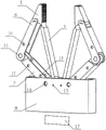
图1是本发明一种绳牵引刚柔耦合变刚度夹持器的立体图;1 is a perspective view of a rope traction rigid-flexible coupling variable rigidity gripper of the present invention;
图2是本发明一种绳牵引刚柔耦合变刚度夹持器的柔性机构的立体图;2 is a perspective view of a flexible mechanism of a rope traction rigid-flexible coupling variable-rigidity gripper of the present invention;
图3是本发明一种绳牵引刚柔耦合变刚度夹持器的正视图(以及左夹持和底座的剖面图);Fig. 3 is a front view of a rope traction rigid-flexible coupling variable rigidity gripper of the present invention (and a cross-sectional view of the left gripping and base);
图4是本发明一种绳牵引刚柔耦合变刚度夹持器的弹性牵引装置的绳索路径;Fig. 4 is a rope path of the elastic traction device of a rope traction rigid-flexible coupling variable stiffness gripper of the present invention;
图5是本发明一种绳牵引刚柔耦合变刚度夹持器的顶端夹持杆的放大图;5 is an enlarged view of the top clamping rod of a rope traction rigid-flexible coupling variable rigidity clamp of the present invention;
图6是本发明一种绳牵引刚柔耦合变刚度夹持器精确抓取的简图;6 is a schematic diagram of the precise grasping of a rope traction rigid-flexible coupling variable-stiffness gripper of the present invention;
图7是本发明一种绳牵引刚柔耦合变刚度夹持器动力抓取的简图;7 is a schematic diagram of the power grabbing of a rope traction rigid-flexible coupling variable rigidity gripper of the present invention;
图8是本发明一种绳牵引刚柔耦合变刚度夹持器中根指和底座的关节轴的简图;8 is a schematic diagram of the joint shaft of the root finger and the base of a rope traction rigid-flexible coupling variable rigidity gripper of the present invention;
图9是本发明一种绳牵引刚柔耦合变刚度夹持器的第一绕线柱、第二绕线柱和第三绕线柱的简图;9 is a schematic diagram of the first winding column, the second winding column and the third winding column of a rope traction rigid-flexible coupling variable stiffness gripper of the present invention;
其中,1为顶端夹持杆;2为第一双面柔性转动副;3为柔性夹持杆;4为第二双面柔性转动副;5为连接件;6为末指;7为根指;8为底座;9、15均为铆钉;10为第一绕线柱;11、14均为铰接链;12为第二绕线柱、13为第三绕线柱;16为小孔;17为驱动电机;18为拉伸回弹弹簧;19为牵引绳索;20为扭簧;21为齿状结构;22为微型轴承;23为凹槽;24为螺母。Among them, 1 is the top clamping rod; 2 is the first double-sided flexible rotating pair; 3 is the flexible clamping rod; 4 is the second double-sided flexible rotating pair; 5 is the connecting piece; 6 is the last finger; 7 is the
具体实施方式Detailed ways
下面结合附图与具体实施方式对本发明作进一步详细的描述。The present invention will be described in further detail below with reference to the accompanying drawings and specific embodiments.
实施例Example
如图1至图9所示,本发明一种绳牵引刚柔耦合变刚度夹持器包括内侧柔性机构、外侧刚性抓取机构和驱动电机17,其中,内侧柔性机构由对称设置的柔性左夹持组件与柔性右夹持组件通过连接件5连接组成。而外侧刚性抓取机构包括左驱动组件、右驱动组件、底座8以及对称设置的刚性左夹持组件与刚性右夹持组件,本发明的柔性左夹持组件与柔性右夹持组件通过连接件5和铆钉15与底座8连接,刚性左夹持组件的一端通过铆钉9与柔性左夹持组件连接,另一端与底座8铰接,刚性右夹持组件的一端通过铆钉9与柔性右夹持组件连接,另一端与底座8铰接,而左驱动组件和右驱动组件分别设置在刚性左夹持组件和刚性右夹持组件内部并与驱动电机17连接,实现驱动电机17通过左驱动组件和右驱动组件驱动刚性左夹持组件和刚性右夹持组件进行夹持或张开运动。As shown in FIGS. 1 to 9 , a rope traction rigid-flexible coupling variable-rigidity gripper of the present invention includes an inner flexible mechanism, an outer rigid grabbing mechanism and a
具体地说,柔性左夹持组件与柔性右夹持组件结构相同,均包括依次连接的顶端夹持杆1、第一双面柔性转动副2、柔性夹持杆3和第二双面柔性转动副4,该柔性左夹持组件与柔性右夹持组件均通过第二双面柔性转动副4与连接件5连接,其中,第一双面柔性转动副2和第二双面柔性转动副4均为正圆型双面柔性转动副。本发明采用的正圆型双面柔性转动副的主要特征是:结构简单、易于制造、不需要组装与维护、没有摩擦损失,表现在拓扑结构与其对应的刚度机构类似,多集中柔度型柔性运动副代替传统运动副。Specifically, the flexible left clamping assembly and the flexible right clamping assembly have the same structure, including a
为了增加握住物体的摩擦接触,顶端夹持杆1的表面设置用于增大摩擦力的齿状结构21,这样有利于在平面夹取尺寸较薄的物体,比如,硬币。类似人手在进行精确捏取硬币时,手指甲的作用。In order to increase the frictional contact of holding the object, the surface of the top
本发明的内侧柔性机构为一体成型的橡胶构件。该内侧柔性机构的材料选择的基本原则:其一,主要考虑其强度极限与弹性模量之比。如:聚丙烯、多晶硅、橡胶等为理想的非金属弹性材料。其二,充分考虑材料的抗疲劳指标。确保材料在变形时不会发生张力松弛或蠕变。其三,在以上两点都满足的情况下,考虑材料的经济适用性。The inner flexible mechanism of the present invention is an integrally formed rubber member. The basic principles of material selection of the inner flexible mechanism: First, the ratio of its strength limit and elastic modulus is mainly considered. Such as: polypropylene, polysilicon, rubber, etc. are ideal non-metal elastic materials. Second, fully consider the fatigue resistance of the material. Ensure that the material does not experience tension relaxation or creep when deforming. Third, in the case of satisfying the above two points, consider the economical applicability of the material.
本发明的刚性左夹持组件与刚性右夹持组件结构相同,均包括依次铰接的末指6和根指7,刚性左夹持组件通过末指6与柔性左夹持组件铰接,并通过根指7与底座8铰接,而刚性右夹持组件通过末指6与柔性右夹持组件铰接,并通过根指7与底座8铰接。The rigid left clamping assembly of the present invention has the same structure as the rigid right clamping assembly, and both include a
本发明中末指6与根指7关节处的铰接链11是由关节轴、微型轴承以及内嵌螺母构成。关节轴的两端穿过两个微型轴承,微型轴承内径为4mm、外径为6mm且分别嵌入在末指6与根指7的关节处,内嵌螺母将关节轴固定,实现末指6与根指7的铰接。本发明中根指7与底座8关节处的铰接链14是由关节轴、微型轴承22以及内嵌螺母构成。关节轴的两端由内嵌螺母固定在底座8外壳处,关节轴穿过镶嵌在根指7关节处的两个微型轴承22,并设置了一个凹槽23,实现夹持器的根指7与底座8进行铰接。In the present invention, the
本发明的左驱动组件和右驱动组件结构相同,均包括设置在末指6和根指7内腔的弹性牵引装置和传动装置,该传动装置圈绕弹性牵引装置并穿出底座8与驱动电机17连接。其中,弹性牵引装置包括拉伸回弹弹簧18和扭簧20,扭簧20设置在根指7与底座8的铰接链14处,扭簧20穿过关节轴,并安装在凹槽23内,扭簧20的一端钢丝在根指7处,另一端在底座8处。当夹持器结束夹取物体,可通过扭簧20的自身弹力控制根指7恢复原来张开的位置。The left drive assembly and the right drive assembly of the present invention have the same structure, and both include an elastic traction device and a transmission device arranged in the inner cavity of the
拉伸回弹弹簧18为弹性材料制成的弹性元件,其一端固定在末指6上,另一端依次绕过末指6与根指7的铰接链11的关节轴,以及根指7与底座8的铰接链14的关节轴,拉伸回弹弹簧18与扭簧20位置平行且没有接触。最后,拉伸回弹弹簧18固定于连接件5与底座8连接处的铆钉15,形成夹持器的伸肌腱结构。拉伸回弹弹簧18的设计具有能够满足夹持器保持张开的初始状态,便于对较大物体的抓取操作。本发明凹槽23是为了固定扭簧20,防止夹持器的伸肌腱或者屈肌腱被扭簧20干扰。The
本发明的传动装置包括牵引绳索19、设置在末指6内腔的第一绕线柱10、以及均设置在根指7内腔的第二绕线柱12和第三绕线柱13,其中,第一绕线柱10和第二绕线柱12靠近末指6和根指7的铰接链11设置,第三绕线柱13靠近根指7与底座8的铰接链14设置。而牵引绳索19依次绕过第一绕线柱10、末指6与根指7铰接链11的关节轴、第二绕线柱12、第三绕线柱13以及根指7与底座8的铰接链14的关节轴,最后穿出底座8设置的预留孔16与驱动电机17连接,形成夹持器的屈肌腱结构。具体地说,第一绕线柱10的下侧与牵引绳索19接触,第一绕线柱10两端分别穿过末指6外壳上的两个相互对称的预留孔,由螺母24固定。两端螺母内嵌与末指6外壳处。第二绕线柱12和第三绕线柱13的下侧与牵引绳索19接触,第二绕线柱12和第三绕线柱13的两端分别穿过根指7外侧孔,螺母24内嵌与根指7外壳处。The transmission device of the present invention includes a
本发明是由第一绕线柱10、第二绕线柱12和第三绕线柱13以及铰接链的关节轴将驱动电机17的旋转运动转换成绳索牵引左、右夹持的平面运动。本发明夹持器的伸肌腱结构和屈肌腱结构具有结构简单、原理简单和成本低的特点,对所构成的夹持器原件尺寸要求低,尺寸小,可制作为人手大小。In the present invention, the first winding
本发明牵引绳索19和拉伸回弹弹簧18连接为一体,两者在经过末指6和根指7时,通过末指6底端、根指7顶端和底座8的空隙进行连接。牵引绳19在末指6顶端固定,经过第一绕线柱10下侧、铰接链11的上端、第二绕线柱12和第三绕线柱13下侧以及铰接14上端,穿过16预留孔与驱动电机17连接。驱动电机17通过转动内部的第一绕线柱10、第二绕线柱12和第三绕线柱13对牵引绳进行缠绕,使之可以产生牵引绳19收缩。驱动电机17对牵引绳19的拉力通过预留孔16到达铰接链14的关节轴,关节轴与牵引绳19接触,改变拉力的方向,使牵引绳19拉力继续沿牵引绳19对三个绕线柱切线法线的方向有一个向上的力,即左夹持组件有一个由左向右向内闭合的力。对称的,右夹持组件有一个由右向左向内闭合的力。牵引绳19尽量竖直穿过底座的预留孔16,可以减少摩擦。而驱动电机17可选取伺服电机、步进电机等。本实施例通过绳索牵引欠驱动的驱动方式结构简单、尺寸小,具有良好的自适应性,其能够实现多工作模式的同时不需要大量的驱动器和复杂的控制算法。The
当夹持器在抓取物体时,针对其抓取对象在两点夹持以及包络夹持时夹持器的开口大小进行优化设计,得出最佳的牵引绳和伸肌腱的拉伸长度。结合内侧柔性机构的变形力和电机提供的绳索拉力计算出所需夹持器的抓取力。When the gripper is grasping the object, the opening size of the gripper is optimized according to the two-point gripping and envelope gripping of the grasped object, and the optimal stretched length of the traction rope and the extensor tendon is obtained. The required gripping force of the gripper is calculated by combining the deformation force of the inner flexible mechanism and the rope tension provided by the motor.
非工作状态下的夹持器,由于伸肌腱结构、扭簧20以及内侧柔性机构的弹力,使夹持器保持张开的最大状态。当夹持器工作时,控制驱动电机17正转,通过牵引绳19一端,固定在驱动电机17转动轴上,另一端固定在末指6顶端,使牵引绳19绷直对夹持器的屈肌腱结构产生拉力。本实例中,驱动电机17转动轴同时驱动夹持器左右两根屈肌腱结构,使夹持器左右两根手指同时弯曲,并带动内侧柔性机构弯曲。如图6所示,当夹持器在抓取直径较小的物体时,可对其进行精确夹持,接触到柔性左夹持组件和柔性右夹持组件的顶端夹持杆1时,刚性左夹持组件和刚性右夹持组件的末指6与根指7由屈肌腱结构的收缩,带动顶端夹持杆1向内抓取物体。如图7所示,当夹持器抓取直径较大的物体时,物体从末指6到根指7连续接触从而确保其包络夹持,同时刚性左夹持组件和刚性右夹持组件被驱动电机17控制完成一个完整的开环抓取控制。夹持器松开夹持对象时,驱动电机17反转。使屈肌腱结构沿原路径变松,由伸肌腱结构、扭簧以及内侧柔性机构的弹力使夹持器恢复最初状态。In the non-working state of the gripper, due to the elastic force of the extensor tendon structure, the
上述实施例为本发明较佳的实施方式,但本发明的实施方式并不受上述实施例的限制,其他的任何未背离本发明的精神实质与原理下所作的改变、修饰、替代、组合、简化,均应为等效的置换方式,都包含在本发明的保护范围之内。The above-mentioned embodiments are preferred embodiments of the present invention, but the embodiments of the present invention are not limited by the above-mentioned embodiments, and any other changes, modifications, substitutions, combinations, The simplification should be equivalent replacement manners, which are all included in the protection scope of the present invention.
Claims (7)
Priority Applications (1)
| Application Number | Priority Date | Filing Date | Title |
|---|---|---|---|
| CN202110105280.2A CN112809727B (en) | 2021-01-26 | 2021-01-26 | A rope traction rigid-flexible coupling variable stiffness gripper |
Applications Claiming Priority (1)
| Application Number | Priority Date | Filing Date | Title |
|---|---|---|---|
| CN202110105280.2A CN112809727B (en) | 2021-01-26 | 2021-01-26 | A rope traction rigid-flexible coupling variable stiffness gripper |
Publications (2)
| Publication Number | Publication Date |
|---|---|
| CN112809727A CN112809727A (en) | 2021-05-18 |
| CN112809727B true CN112809727B (en) | 2022-07-29 |
Family
ID=75859399
Family Applications (1)
| Application Number | Title | Priority Date | Filing Date |
|---|---|---|---|
| CN202110105280.2A Active CN112809727B (en) | 2021-01-26 | 2021-01-26 | A rope traction rigid-flexible coupling variable stiffness gripper |
Country Status (1)
| Country | Link |
|---|---|
| CN (1) | CN112809727B (en) |
Families Citing this family (1)
| Publication number | Priority date | Publication date | Assignee | Title |
|---|---|---|---|---|
| WO2024254685A1 (en) * | 2023-06-12 | 2024-12-19 | Lionel Birglen | Mechanical finger with variable stiffness |
Citations (6)
| Publication number | Priority date | Publication date | Assignee | Title |
|---|---|---|---|---|
| KR20040046005A (en) * | 2002-11-26 | 2004-06-05 | 한국과학기술원 | Robot gripper based on the cable mechanism |
| CN102689309A (en) * | 2012-05-29 | 2012-09-26 | 江南大学 | Compliant passive gripper drawn by pneumatic ropes and provided with bent plate spring skeleton |
| CN106926266A (en) * | 2017-02-27 | 2017-07-07 | 哈尔滨工业大学深圳研究生院 | A kind of rope drives the mechanical clamping device of linkage |
| CN106976101A (en) * | 2017-05-15 | 2017-07-25 | 福州大学 | A kind of drive lacking two refers to crawl Dextrous Hand and its method of work |
| CN110561478A (en) * | 2019-09-30 | 2019-12-13 | 佛山科学技术学院 | A rigid-flexible coupling gripper |
| CN111015713A (en) * | 2019-12-11 | 2020-04-17 | 佛山科学技术学院 | Manipulator capable of enhancing clamping force |
Family Cites Families (2)
| Publication number | Priority date | Publication date | Assignee | Title |
|---|---|---|---|---|
| EP3383599A4 (en) * | 2015-12-03 | 2019-10-30 | SRI International Inc. | PREHENSEUR DE ROBOT |
| CN107199573A (en) * | 2017-07-08 | 2017-09-26 | 佛山市正略信息科技有限公司 | A kind of production line clamping workpiece manipulator |
-
2021
- 2021-01-26 CN CN202110105280.2A patent/CN112809727B/en active Active
Patent Citations (6)
| Publication number | Priority date | Publication date | Assignee | Title |
|---|---|---|---|---|
| KR20040046005A (en) * | 2002-11-26 | 2004-06-05 | 한국과학기술원 | Robot gripper based on the cable mechanism |
| CN102689309A (en) * | 2012-05-29 | 2012-09-26 | 江南大学 | Compliant passive gripper drawn by pneumatic ropes and provided with bent plate spring skeleton |
| CN106926266A (en) * | 2017-02-27 | 2017-07-07 | 哈尔滨工业大学深圳研究生院 | A kind of rope drives the mechanical clamping device of linkage |
| CN106976101A (en) * | 2017-05-15 | 2017-07-25 | 福州大学 | A kind of drive lacking two refers to crawl Dextrous Hand and its method of work |
| CN110561478A (en) * | 2019-09-30 | 2019-12-13 | 佛山科学技术学院 | A rigid-flexible coupling gripper |
| CN111015713A (en) * | 2019-12-11 | 2020-04-17 | 佛山科学技术学院 | Manipulator capable of enhancing clamping force |
Also Published As
| Publication number | Publication date |
|---|---|
| CN112809727A (en) | 2021-05-18 |
Similar Documents
| Publication | Publication Date | Title |
|---|---|---|
| CN109176568B (en) | A rigid-soft coupled multi-fingered dexterous hand driven by tendon and electromagnetic force | |
| CN108908382A (en) | The coupling adaptive three of tendon rope drive refers to differential mechanism manpower jaw arrangement | |
| CN101804633B (en) | Tendon rope parallel skillful under-driven bionic robot finger device | |
| CN105364938B (en) | Belt wheel collaboration locking linkage adaptive robot finger apparatus | |
| CN104889998B (en) | Underactuated Robotic Finger Device with Envelope and Grip | |
| CN108994864A (en) | Double tendon rope tandem coupling adaptive finger apparatus | |
| CN105619440B (en) | Open chain flexible piece puts down folder adaptive robot finger apparatus | |
| CN105150225A (en) | Pinching-holding composite and adaptive robot finger device with rod and wheels connected in parallel | |
| CN101716767B (en) | Coupling underactuated integrated bionic hand device | |
| CN107363856B (en) | Self-adaptive finger, two-claw mechanical arm and robot | |
| CN100551640C (en) | Underactuated robot finger device with tendon rope gear | |
| CN111496828A (en) | A dexterous underactuated bionic gripper at the end of a robot | |
| CN101653941A (en) | Sliding block type direct under-actuated bionic hand device with changeable holding power | |
| CN113370241A (en) | Large-bearing multi-finger type soft manipulator with net structure | |
| CN113799162B (en) | Robot grabbing paw for special-shaped objects | |
| CN112720558A (en) | Flexible finger-tip robot hand directly driven by motor | |
| CN106799742A (en) | Accurate flat folder self adaptation and coupling adaptive pattern switching robot finger apparatus | |
| CN112809727B (en) | A rope traction rigid-flexible coupling variable stiffness gripper | |
| CN211440027U (en) | Sensory-triggered zero-delay transmission flat-clamp adaptive robot finger device | |
| CN207696544U (en) | Tendon drive-type bionic mechanical hand | |
| CN101829995B (en) | Crank block type flexible piece parallel coupled under-actuated finger device | |
| CN101664930B (en) | Coupling underactuated integral finger device of double-joint robot | |
| CN212287680U (en) | Sliding block flexible piece flat clamping indirect self-adaptive robot hand device | |
| CN102699926A (en) | Under-actuated robot finger device with multiple switchable grab modes | |
| CN212331062U (en) | A slider-type underactuated three-joint manipulator |
Legal Events
| Date | Code | Title | Description |
|---|---|---|---|
| PB01 | Publication | ||
| PB01 | Publication | ||
| SE01 | Entry into force of request for substantive examination | ||
| SE01 | Entry into force of request for substantive examination | ||
| GR01 | Patent grant | ||
| GR01 | Patent grant | ||
| CP03 | Change of name, title or address |
Address after: No.33, Guangyun Road, Nanhai District, Foshan City, Guangdong Province, 528200 Patentee after: Foshan University Country or region after: China Address before: No.33, Guangyun Road, Nanhai District, Foshan City, Guangdong Province, 528200 Patentee before: FOSHAN University Country or region before: China |
|
| CP03 | Change of name, title or address |