Steam sterilizer
Technical Field
The invention relates to the technical field of medical instruments, in particular to a steam sterilizer.
Background
Among the prior art, steam sterilizer is used mostly to disinfect medical instrument, and steam sterilizer includes: a housing for supporting and positioning other components of the steam sterilizer; a main tank for containing water; a sterilization chamber for housing instruments to be sterilized; the hatch cover is fixedly connected with the disinfection cabin in a rotating way and/or fixedly connected with the disinfection cabin in a detachable way and is used for sealing the disinfection cabin and facilitating the entry and exit of the instruments to be disinfected into and out of the disinfection cabin; a supply system adapted to draw water from the main tank, convert it into steam, and deliver the steam to the disinfection chamber; drying means adapted to dry the apparatus using a jet of hot air; an exhaust system adapted to exhaust waste fluids, the waste fluids being waste liquids and residual gases and vapors.
Because steam sterilizer is at the during operation, its disinfection storehouse internal pressure is higher, and the hatch board atress is great this moment, especially the hookup location in hatch board and disinfection storehouse, stress concentration can appear, exists great potential safety hazard when seriously harming steam sterilizer's life.
Disclosure of Invention
The embodiment of the application provides a steam sterilizer, solves the technical problem that hatch covers and positioning assemblies thereof are easily damaged in the working process of the steam sterilizer, and further potential safety hazards are caused, and achieves the technical effect of stable and reliable operation of the steam sterilizer.
The embodiment of the application provides a steam sterilizer, which comprises a shell, a sterilization bin, a drying device, a supply system, a discharge system, a power assembly, a control unit, a sterilization bin lifting assembly and a sealing plate assembly, wherein the sterilization bin lifting assembly is arranged on the shell;
the disinfection cabin main body is a hollow cylindrical structure with one open end and is used for providing space for disinfection of medical instruments;
the disinfection cabin is positioned on the shell in a sliding mode and comprises a sealing element;
the sealing element is positioned on the disinfection cabin at a position close to the opening and is used for preventing steam from being output from the opening of the disinfection cabin when disinfection is started;
the disinfection cabin sliding driving device is positioned between the disinfection cabin and the shell and is used for driving the disinfection cabin to slide;
the sealing plate assembly is positioned on the shell, and the main body is in a plate shape;
before disinfection, the disinfection bin slides towards the sealing plate assembly, and the sealing plate assembly seals the opening of the disinfection bin.
The preferred sealing plate assembly comprises a sealing plate main body, a sealing plate positioning assembly, a cover body and a sealing plate rotating assembly;
the sealing plate main body is a circular plate or a fan-shaped plate, and can be rotatably positioned on the shell through the sealing plate positioning assembly;
the axial direction of the sealing plate main body is the same as the sliding direction of the disinfection cabin;
the cover body is positioned on the sealing plate main body and is used for placing medical instruments to be sterilized into the sterilizing bin and taking out the sterilized medical instruments from the sterilizing bin after the medical instruments are sterilized;
the sealing plate rotating assembly plays a role in driving the sealing plate main body to rotate so as to change the space position of the cover body relative to the disinfection cabin.
The preferred still includes puts the thing bucket, puts the thing bucket and is used for putting the medical instrument disinfected;
the storage barrel is positioned inside the disinfection cabin through the storage barrel positioning assembly and comprises a storage barrel main body, wherein the storage barrel main body is barrel-shaped, and air holes are densely distributed in the storage barrel main body.
The preferred disinfection bin also comprises a steam inlet hole and a steam outlet hole;
the steam inlet hole and the steam outlet hole are positioned on the side wall of the disinfection bin and are respectively communicated with the supply system and the discharge system;
the storage barrel is rotatably and fixedly connected to the disinfection bin through a storage barrel positioning assembly;
the storage barrel also comprises a protruding plate and an air inlet flow guide block;
the protruding plate is positioned on the outer wall of the storage barrel main body;
the air inlet airflow guide block is positioned on the inner wall of the disinfection bin and close to the steam inlet hole;
high-pressure steam enters the disinfection bin through the steam inlet hole under the guidance of the air inlet airflow guide block and blows towards the protruding plate to further push the storage barrel to rotate.
Preferably, the storage barrel further comprises a clamping assembly;
the clamping assembly is positioned on the inner wall of the storage barrel body, and plays a role in positioning and placing medical instruments in the storage barrel.
The preferred clamping assembly comprises a forceps body, a forceps body positioning assembly, a forceps body rotating assembly and a clamping action auxiliary block;
the forceps body main body is V-shaped and is used for clamping and further positioning the disinfected medical instrument, and the forceps body can be rotatably and fixedly connected to the storage barrel main body through the forceps body positioning component;
the forceps body rotating assembly is used for driving the forceps bodies to rotate so as to be matched with the clamping action auxiliary block to clamp the medical instrument to be disinfected;
the main body of the auxiliary clamping action block is V-shaped, and when the forceps body rotates, the forceps body is contacted with the auxiliary clamping action block and then extruded to realize clamping action;
the operation of the clamping assembly is manually controlled to clamp and release or controlled by the control unit.
The preferable forceps body rotating assembly comprises a central power bin, a reversing wheel, a force guiding rope and a force guiding rope retracting assembly;
the central power bin is rotatably and fixedly connected to the storage barrel and positioned on the storage barrel positioning assembly, and the main body of the central power bin is hollow and cylindrical, and the axial direction of the main body of the central power bin is the same as that of the storage barrel;
the reversing wheel is positioned on the side wall of the central power bin and is used for guiding the force guide rope;
the force guide rope retracting and releasing assembly is positioned in the central power bin and plays a role in retracting and releasing the force guide rope so as to control the tweezers body to rotate;
one end of the force guide rope is positioned on the forceps body, and the other end of the force guide rope is wound and positioned on the force guide rope retracting assembly.
The preferred clamping assembly comprises a forceps body, a forceps body positioning assembly, a forceps body rotating assembly and a clamping action auxiliary block;
the main body of the auxiliary clamping action block is V-shaped, and when the forceps body rotates, the forceps body is contacted with the auxiliary clamping action block and then extruded to realize clamping action;
the forceps body main body is X-shaped, the number of the clamping action auxiliary blocks is two, the clamping action auxiliary blocks are positioned on the inner wall of the storage barrel main body, and the clamping action auxiliary blocks are positioned at the two ends, close to the forceps body, of the clamping action auxiliary blocks in spatial positions;
the clamping assembly also comprises a cover plate which is positioned on the inner wall of the storage barrel main body and is used for positioning the reversing wheel;
the forceps body positioning component is used for positioning the forceps bodies, and the forceps body rotating component plays a role in driving the forceps bodies to rotate;
the number of the forceps bodies is multiple, the specifications are multiple, and the forceps bodies are used for positioning medical instruments which are not used.
Preferably the tweezer body comprises a first tweezer body and a second tweezer body;
the first forceps body and the second forceps body rotate asynchronously and are clamped asynchronously.
The sealing plate positioning assembly preferably comprises a supporting rod, a positioning block and an elastic element;
the main body of the supporting rod is rod-shaped or column-shaped and is fixed on the shell;
the positioning block is fixed on the supporting rod and used for positioning the sealing plate main body;
the sealing plate main body is rotatably connected to the positioning block;
the sealing plate is characterized in that an elastic element is positioned between the positioning block and the sealing plate main body, and the elastic element is used for ejecting the sealing plate main body away from the shell under the non-disinfection state of the steam sterilizer so as to facilitate the rotation of the sealing plate main body. One or more technical solutions provided in the embodiments of the present application have at least the following technical effects or advantages:
set up through the hatch board of cancellation steam sterilizer, add and seal the board subassembly and replace hatch board closed disinfection storehouse, seal the board subassembly and fix a position on steam sterilizer's casing, disinfection storehouse slide orientation is in steam sterilizer's casing, and disinfection storehouse below sets up disinfection storehouse lifting unit, and before beginning the disinfection, utilize disinfection storehouse lifting unit to lift the storehouse of disinfecting and make it hug closely the seal board subassembly and then seal the disinfection storehouse. The technical problem that the hatch cover and the positioning assembly of the hatch cover are easily damaged in the working process of the steam sterilizer, so that potential safety hazards are caused is effectively solved, and the technical effect of stable and reliable operation of the steam sterilizer is further realized.
Drawings
FIG. 1 is a schematic view showing the internal structure of a steam sterilizer of the present invention, showing the internal structure of the steam sterilizer;
FIG. 2 is a schematic view showing the internal construction of the steam sterilizer of the present invention;
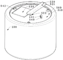
FIG. 3 is a schematic view of the outer structure of the steam sterilizer of the present invention;
FIG. 4 is a cross-sectional view of the steam sterilizer of the present invention;
FIG. 5 is a schematic view of the closure plate assembly of the steam sterilizer of the present invention;
FIG. 6 is a schematic view of the positional relationship between the sterilization chamber and the housing of the steam sterilizer of the present invention;
FIG. 7 is a schematic view showing the positional relationship between the sterilizing compartment slide driving means and the sterilizing compartment of the steam sterilizer of the present invention;
FIG. 8 is a schematic view of the structure of the inlet airflow guide block of the steam sterilizer of the present invention;
FIG. 9 is a schematic view of the storage tub of the steam sterilizer of the present invention;
FIG. 10 is a schematic view of the positioning of the clamping assembly and the storage tub body of the steam sterilizer of the present invention;
FIG. 11 is a schematic view of a first configuration of a clamping assembly of the steam sterilizer of the present invention;
FIG. 12 is a schematic view of the structure of the tweezer body of the steam sterilizer of the present invention;
FIG. 13 is a schematic view of a second configuration of a clamping assembly of the steam sterilizer of the present invention;
FIG. 14 is a schematic view of a second form of a clamp assembly of the steam sterilizer of the present invention;
FIG. 15 is a schematic view of a third configuration of a clamping assembly of the steam sterilizer of the present invention;
FIG. 16 is a schematic view of a third form of a clamp assembly of the steam sterilizer of the present invention;
in the figure:
a housing 100, a gas exchange hole 110,
A disinfection bin 200, a steam inlet hole 210, a steam outlet hole 220, a positioning component 230 of a storage barrel, an air inlet flow guide block 240,
A disinfection bin sliding driving device 300,
The storage barrel 400, the storage barrel main body 410, the air holes 420, the sealing element 430, the protruding plate 440, the clamping component 450, the tweezer body 451, the buffer cushion 4511, the first tweezer body 4512, the second tweezer body 4513, the tweezer body positioning component 452, the tweezer body rotating component 453, the central power bin 4531, the reversing wheel 4532, the force guide rope 4533, the force guide rope retracting component 4534, the clamping action auxiliary block 454, the clamping component 450, the tweezer body rotating component 451, the buffer cushion 4511, the first twee,
The sealing plate assembly 500, the sealing plate body 510, the sealing plate positioning assembly 520, the supporting rod 521, the positioning block 522, the elastic element 523, the cover 530, the sealing plate rotating assembly 540, the rotating handle 541 and the auxiliary wheel 542;
Detailed Description
In order to facilitate an understanding of the present invention, the present application will now be described more fully with reference to the accompanying drawings; the preferred embodiments of the present invention are illustrated in the accompanying drawings, but the invention may be embodied in many different forms and should not be construed as limited to the embodiments set forth herein; rather, these embodiments are provided so that this disclosure will be thorough and complete.
It is noted that the terms "vertical," "horizontal," "upper," "lower," "left," "right," and the like as used herein are for illustrative purposes only and do not represent the only embodiments.
Unless defined otherwise, all technical and scientific terms used herein have the same meaning as commonly understood by one of ordinary skill in the art to which this invention belongs; the terminology used herein in the description of the invention is for the purpose of describing particular embodiments only and is not intended to be limiting of the invention; as used herein, the term "and/or" includes any and all combinations of one or more of the associated listed items.
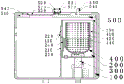
Referring to fig. 1, there is shown a schematic view of the internal structure of the steam sterilizer of the present invention; the steam sterilizer of the present application includes a housing 100, a sterilizing compartment 200, a sterilizing compartment lifting assembly 300, and a sealing plate assembly 500; this application is through the setting of the hatch board of cancellation steam sterilizer, add seal plate subassembly 500 and replace hatch board closed disinfection storehouse 200, seal plate subassembly 500 and fix a position on steam sterilizer's casing 100, disinfection storehouse 200 slide orientation is in steam sterilizer's casing 100, disinfection storehouse 200 below sets up disinfection storehouse lifting unit 300, before beginning the disinfection, utilize disinfection storehouse lifting unit 300 to lift disinfection storehouse 200 and make it hug closely seal plate subassembly 500 and then seal disinfection storehouse 200.
Example one
As shown in FIG. 1, the steam sterilizer of the present application includes a housing 100, a sterilization chamber 200, a sterilization chamber lift assembly 300, a sealing plate assembly 500, a drying device, a supply system, an exhaust system, a power assembly, and a control unit.
The whole casing of the steam sterilizer of the shell 100 plays a role of bearing various parts of the steam sterilizer, and the shape of the casing can be a box structure; the side wall of the housing 100 is provided with two or more gas exchange holes 110, and the gas exchange holes 110 are used for communicating with the supply system and the exhaust system to input steam into the sterilization chamber 200 or exhaust gas in the sterilization chamber 200.
As shown in fig. 1, 7 or 8, the main body of the disinfection chamber 200 is a hollow cylindrical structure with an open end, and is used for providing a space for disinfecting medical instruments; the sterilizing chamber 200 is slidably positioned on the housing 100, the sterilizing chamber 200 comprises a steam inlet hole 210, a steam outlet hole 220 and a sealing element 250; the steam inlet hole 210 and the steam outlet hole 220 are positioned on the side wall of the disinfection bin 200 and are respectively used for being communicated with the supply system and the discharge system; the sealing member 250 is positioned on the sterilization chamber 200 near the opening for preventing steam from being discharged from the opening of the sterilization chamber when sterilization is started.
Preferably, the steam inlet hole 210 and the steam outlet hole 220 are both oblong holes, and are matched with the gas exchange hole 110.
Preferably, the sliding direction of the sterilizing chamber 200 is the height direction of the steam sterilizer.
Preferably, the sealing element 250 is a rubber gasket.
The disinfection cabin sliding driving device 300 is positioned between the disinfection cabin 200 and the shell 100 and is used for driving the disinfection cabin 200 to slide; the structure of the disinfection bin sliding driving device 300 can be a gear rack mechanism, a telescopic rod mechanism, a cam mechanism and the like.
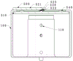
As shown in fig. 3, 4 or 5, the sealing plate assembly 500 is positioned on the housing 100, and has a plate shape as a main body, which serves to close the opening of the sterilization chamber 200 during sterilization;
further, the sealing plate assembly 500 includes a sealing plate body 510, a sealing plate positioning assembly 520, a cover 530, and a sealing plate rotating assembly 540; the sealing plate body 510 is a circular plate or a fan-shaped plate, and can be rotatably positioned on the shell 100 through the sealing plate positioning assembly 520; when the steam sterilizer operates, the contact area of the surface of the sealing plate main body 510, which is far away from the sterilizing chamber 200, and the shell 100 is more than one twenty-sixth of the area of the surface; the axial direction of the sealing plate main body 510 is the same as the sliding direction of the disinfection cabin 200; the cover 530 is positioned on the sealing plate main body 510 and is used for placing medical instruments to be sterilized into the sterilization chamber 200 and taking out the sterilized medical instruments from the inside of the sterilization chamber 200 after the sterilization of the medical instruments is completed; the sealing plate rotating assembly 540 functions to drive the sealing plate main body 510 to rotate so as to change the spatial position of the cover 530 relative to the sterilizing chamber 200;
further, as shown in fig. 1 and 4, the sealing plate positioning assembly 520 includes a supporting rod 521, a positioning block 522 and an elastic element 523; the main body of the support rod 521 is rod-shaped or column-shaped and is fixed on the housing 100; the positioning block 522 is fixed on the support rod 521 and used for positioning the sealing plate main body 510; the sealing plate main body 510 is rotatably connected to the positioning block 522; an elastic element 523 is positioned between the positioning block 522 and the sealing plate main body 510, and the elastic element 523 is used for pushing the sealing plate main body 510 away from the housing 100 in a non-sterilization state of the steam sterilizer, so that the sealing plate main body 510 can rotate and the state of the sterilization chamber 200 can be displayed.
Further, as shown in fig. 3, the sealing plate rotating assembly 540 includes a rotating handle 541 and auxiliary wheels 542; the rotating handle 541 is positioned on the sealing plate main body 510; the auxiliary wheel 542 is rotatably fixed to the sealing plate body 510 and abuts against the housing 100, and the axial direction of the auxiliary wheel 542 is the same as the axial direction of the sealing plate body 510, so that a user can rotate the sealing plate body 510 conveniently; preferably, the number of the auxiliary wheels 542 is three.
As shown in fig. 2, the drying device, the supply system, the discharge system, the power assembly and the control unit are all in the prior art and will not be described in detail herein.
Preferably, the control unit comprises a control panel, and the control panel plays a role in controlling the operation of each part of the equipment.
Preferably, a plurality of control keys are positioned on the control panel;
preferably, the control panel is a touch screen;
the application steps of the embodiment of the application are as follows in sequence: an operator rotates the sealing plate main body 510 to rotate the cover 530 right above the sterilizing chamber 200; opening the cover 530, and placing the medical apparatus to be sterilized into the sterilization chamber 200; rotating the closure plate body 510 until the opening of the sterilization chamber 200 is not visible from the lid 530; the operator controls the disinfection cabin sliding driving device 300 to operate through the control unit, so that the sealing assembly 250 on the opening of the disinfection cabin 200 is tightly attached to the sealing plate main body 510; the control unit controls the supply system and the discharge system to operate to start disinfection; after the disinfection is finished, the supply system and the discharge system are stopped, the disinfection bin sliding driving device 300 is operated, and the disinfection bin 200 is far away from the sealing plate main body 510; the sealing plate main body 510 is rotated to rotate the cover 530 right above the sterilization chamber 200, the cover 530 is opened, and the sterilized medical instrument is taken out.
The technical scheme in the embodiment of the application at least has the following technical effects or advantages:
the technical problem that the hatch cover and the positioning assembly of the hatch cover are easily damaged in the working process of the steam sterilizer, so that potential safety hazards are caused is solved, and the technical effect of stable and reliable operation of the steam sterilizer is realized.
Example two
Considering that part of the surface of the medical instrument put into the disinfection cabin 200 can be attached to the inner wall of the disinfection cabin 200, thereby affecting the sterilization effect; the present embodiment is added with the storage barrel 400 for placing the sterilized medical apparatus on the basis of the above embodiments.
As shown in fig. 1, 6 and 9, the storage barrel 400 is positioned inside the sterilizing chamber 200 by the storage barrel positioning assembly 230, the storage barrel 400 includes a storage barrel main body 410, and the storage barrel main body 410 is barrel-shaped and has air holes 420 densely distributed thereon.
Considering that the contact degree and the heating degree of the medical instrument close to the steam inlet hole 210 and the medical instrument far from the steam inlet hole 210 are different from each other, the disinfection is affected; to solve this problem, as shown in fig. 8 and 9, in this embodiment, the storage barrel 400 is rotatably and fixedly connected to the sterilizing compartment 200 by the storage barrel positioning assembly 230, a protruding plate 440 is additionally provided on the outer wall of the storage barrel main body 410, and an intake airflow guide block 240 is additionally provided on the inner wall of the sterilizing compartment 200 at a position close to the steam intake hole 210; high-pressure steam enters the sterilizing chamber 200 through the steam inlet holes 210 and under the guidance of the air inlet flow guide block 240, and is blown to the protruding plate 440 to push the storage barrel 400 to rotate, so that medical instruments inside the storage barrel 400 can be sterilized uniformly.
The technical scheme in the embodiment of the application at least has the following technical effects or advantages:
further enhancing the sterilization effect and shortening the time required for sterilization to a certain extent.
EXAMPLE III
In the second embodiment, along with the rotation of the storage barrel 400, the medical devices to be sterilized inside the storage barrel 400 are likely to be displaced, and collision occurs, so that the operation noise of the device is generated, and the storage barrel 400 is likely to be damaged while the medical devices to be sterilized are damaged.
In this embodiment, a clamping assembly 450 is added on the basis of the above embodiments, and the clamping assembly 450 is positioned on the inner wall of the storage barrel main body 410 and plays a role in positioning the medical apparatus placed in the storage barrel 400;
further, as shown in fig. 10, 11 and 12, the holding assembly 450 includes a forceps body 451, a forceps body positioning assembly 452, a forceps body rotating assembly 453 and a holding action auxiliary block 454;
the main body of the tweezer body 451 is V-shaped and is used for clamping and further positioning the medical instruments to be disinfected, and the tweezer body 451 can be rotatably and fixedly connected to the main body 410 of the storage barrel through the tweezer body positioning component 452; the forceps body rotating assembly 453 is used for driving the forceps body 451 to rotate so as to cooperate with the clamping action auxiliary block 454 to clamp the medical instrument to be disinfected; the main body of the auxiliary clamping block 454 is in a V shape, and when the forceps body 451 rotates, the forceps body 451 is contacted with the auxiliary clamping block 454 and then is squeezed, so that the clamping action is realized.
Further, the tweezer body rotating assembly 453 comprises a central power bin 4531, a reversing wheel 4532, a force guiding rope 4533 and a force guiding rope retracting assembly 4534; the central power bin 4531 is rotatably and fixedly connected to the storage barrel 400 and is positioned on the storage barrel positioning component 230, and the main body of the central power bin 4531 is hollow and cylindrical, and the axial direction of the central power bin 4531 is the same as that of the storage barrel 400; the reversing wheel 4532 is positioned on the side wall of the central power bin 4531 and is used for guiding the force guide rope 4533; the lead rope retracting component 4534 is positioned in the central power bin 4531 and plays a role in retracting the lead rope 4533 so as to control the rotation of the tweezer body 451; one end of the lead wire 4533 is positioned on the tweezer body 451, and the other end is wound and positioned on the lead wire take-up and pay-off assembly 4534.
Preferably, as shown in fig. 12, a buffering cushion 4511 is positioned on the forceps body 451, and the buffering cushion 4511 plays roles of reducing the wear of the medical instrument and ensuring the clamping firmness.
Preferably, the operation of the clamping assembly 450 is manually controlled to clamp and release or controlled by the control unit.
In practical operation of the embodiment of the present application, the cover 530 is opened, the medical devices to be sterilized are placed in the sterilization chamber 200, and the clamping assemblies 450 are used to position the medical devices to be sterilized in the sterilization chamber 200; when the sterilized medical instrument is removed, the clamping assembly 450 is first released from positioning the medical instrument.
Example four
In consideration of the practical application of the above embodiment, the problem that the disinfection is not thorough enough may occur at the position where the fixed medical instrument is in direct contact with the forceps body 451, which affects the overall disinfection effect; in this embodiment, on the basis of the above embodiments, the clamping assembly 450 is modified, specifically:
as shown in fig. 13 and 14, the main body of the tweezer body 451 is "X" shaped, the number of the auxiliary gripping blocks 454 is two, and the auxiliary gripping blocks 454 are positioned on the inner wall of the main body 410 of the storage barrel and are spatially located at two ends of the auxiliary gripping blocks 454 close to the tweezer body 451; the clamping assembly 450 further comprises a cover plate 4535, wherein the cover plate 4535 is positioned on the inner wall of the storage bucket body 410 and is used for positioning the reversing wheel 4532; the tweezer body positioning assembly 452 is used for positioning the tweezer body 451, and the tweezer body rotating assembly 453 serves to drive the tweezer body 451 to rotate.
Preferably, the forceps body 451 has a plurality of numbers and specifications, and is used for positioning different medical instruments.
In practical operation of the embodiment of the present application, during the sterilization process, the control unit controls the operation of the forceps body rotating assembly 453 to cyclically clamp and release the medical instruments being sterilized.
EXAMPLE five
In the experiment, the problem that the medical instrument being sterilized is easily fixed by the forceps body 451 in the fourth embodiment in the rotating process is found, and the medical instrument is loosened to bring adverse effect to the sterilization;
in order to solve the above problem, as shown in fig. 15 and 16, in this embodiment, on the basis of the fourth embodiment, a single tweezer body 451 is split into two tweezer bodies 451 which rotate asynchronously, which are a first tweezer body 4512 and a second tweezer body 4513, and the tweezer body rotating assembly 453 is adapted to clamp the first tweezer body 4512 and the second tweezer body 4513 asynchronously.
In practical operation of the embodiment of the present application, during a sterilization process, the control unit controls the operation of the forceps body rotating assembly 453, and the first forceps body 4512 and the second forceps body 4513 cyclically clamp and release a medical device being sterilized; at any time during the sterilization process, at least one of the first tweezer body 4512 and the second tweezer body 4513 is in a clamped state.
The above description is only a preferred embodiment of the present invention and is not intended to limit the present invention, and various modifications and changes may be made by those skilled in the art. Any modification, equivalent replacement, or improvement made within the spirit and principle of the present invention should be included in the protection scope of the present invention.