CN112972713B - a steam sterilizer - Google Patents
a steam sterilizer Download PDFInfo
- Publication number
- CN112972713B CN112972713B CN202110416777.6A CN202110416777A CN112972713B CN 112972713 B CN112972713 B CN 112972713B CN 202110416777 A CN202110416777 A CN 202110416777A CN 112972713 B CN112972713 B CN 112972713B
- Authority
- CN
- China
- Prior art keywords
- main body
- assembly
- sealing plate
- disinfection
- positioning
- Prior art date
- Legal status (The legal status is an assumption and is not a legal conclusion. Google has not performed a legal analysis and makes no representation as to the accuracy of the status listed.)
- Expired - Fee Related
Links
Images


Classifications
-
- A—HUMAN NECESSITIES
- A61—MEDICAL OR VETERINARY SCIENCE; HYGIENE
- A61L—METHODS OR APPARATUS FOR STERILISING MATERIALS OR OBJECTS IN GENERAL; DISINFECTION, STERILISATION OR DEODORISATION OF AIR; CHEMICAL ASPECTS OF BANDAGES, DRESSINGS, ABSORBENT PADS OR SURGICAL ARTICLES; MATERIALS FOR BANDAGES, DRESSINGS, ABSORBENT PADS OR SURGICAL ARTICLES
- A61L2/00—Disinfection or sterilisation of materials or objects, in general; Accessories therefor
- A61L2/02—Disinfection or sterilisation of materials or objects, in general; Accessories therefor using physical processes
- A61L2/04—Heat
- A61L2/06—Hot gas
- A61L2/07—Steam
-
- A—HUMAN NECESSITIES
- A61—MEDICAL OR VETERINARY SCIENCE; HYGIENE
- A61L—METHODS OR APPARATUS FOR STERILISING MATERIALS OR OBJECTS IN GENERAL; DISINFECTION, STERILISATION OR DEODORISATION OF AIR; CHEMICAL ASPECTS OF BANDAGES, DRESSINGS, ABSORBENT PADS OR SURGICAL ARTICLES; MATERIALS FOR BANDAGES, DRESSINGS, ABSORBENT PADS OR SURGICAL ARTICLES
- A61L2/00—Disinfection or sterilisation of materials or objects, in general; Accessories therefor
- A61L2/24—Apparatus using programmed or automatic operation
-
- A—HUMAN NECESSITIES
- A61—MEDICAL OR VETERINARY SCIENCE; HYGIENE
- A61L—METHODS OR APPARATUS FOR STERILISING MATERIALS OR OBJECTS IN GENERAL; DISINFECTION, STERILISATION OR DEODORISATION OF AIR; CHEMICAL ASPECTS OF BANDAGES, DRESSINGS, ABSORBENT PADS OR SURGICAL ARTICLES; MATERIALS FOR BANDAGES, DRESSINGS, ABSORBENT PADS OR SURGICAL ARTICLES
- A61L2/00—Disinfection or sterilisation of materials or objects, in general; Accessories therefor
- A61L2/26—Accessories
-
- A—HUMAN NECESSITIES
- A61—MEDICAL OR VETERINARY SCIENCE; HYGIENE
- A61L—METHODS OR APPARATUS FOR STERILISING MATERIALS OR OBJECTS IN GENERAL; DISINFECTION, STERILISATION OR DEODORISATION OF AIR; CHEMICAL ASPECTS OF BANDAGES, DRESSINGS, ABSORBENT PADS OR SURGICAL ARTICLES; MATERIALS FOR BANDAGES, DRESSINGS, ABSORBENT PADS OR SURGICAL ARTICLES
- A61L2103/00—Materials or objects being the target of disinfection or sterilisation
- A61L2103/15—Laboratory, medical or dentistry appliances, e.g. catheters or sharps
-
- A—HUMAN NECESSITIES
- A61—MEDICAL OR VETERINARY SCIENCE; HYGIENE
- A61L—METHODS OR APPARATUS FOR STERILISING MATERIALS OR OBJECTS IN GENERAL; DISINFECTION, STERILISATION OR DEODORISATION OF AIR; CHEMICAL ASPECTS OF BANDAGES, DRESSINGS, ABSORBENT PADS OR SURGICAL ARTICLES; MATERIALS FOR BANDAGES, DRESSINGS, ABSORBENT PADS OR SURGICAL ARTICLES
- A61L2202/00—Aspects relating to methods or apparatus for disinfecting or sterilising materials or objects
- A61L2202/10—Apparatus features
- A61L2202/12—Apparatus for isolating biocidal substances from the environment
- A61L2202/121—Sealings, e.g. doors, covers, valves, sluices
Landscapes
- Health & Medical Sciences (AREA)
- Epidemiology (AREA)
- Life Sciences & Earth Sciences (AREA)
- Animal Behavior & Ethology (AREA)
- General Health & Medical Sciences (AREA)
- Public Health (AREA)
- Veterinary Medicine (AREA)
- Apparatus For Disinfection Or Sterilisation (AREA)
Abstract
一种蒸汽消毒器,包括壳体、消毒仓、干燥装置、供给系统、排出系统、动力组件和控制单元,还包括消毒仓升降组件和封口板组件;所述的消毒仓主体为一端开口的空心柱形结构,用于为医疗器械的消毒提供空间;所述的消毒仓滑动定位在所述的壳体上,消毒仓包括密封元件;所述的密封元件定位在所述的消毒仓上靠近开口的位置,用于在开始消毒时防止蒸汽从消毒仓的开口输出;所述的消毒仓滑动驱动装置定位在所述的消毒仓和所述的壳体之间,用于驱动所述的消毒仓滑动;所述的封口板组件定位在所述的壳体上,主体为板形;在进行消毒前,所述的消毒仓朝向所述的封口板组件滑动,封口板组件封闭所述的消毒仓的开口。

A steam sterilizer, including a shell, a disinfection chamber, a drying device, a supply system, a discharge system, a power assembly and a control unit, and also includes a disinfection chamber lifting assembly and a sealing plate assembly; the main body of the sterilization chamber is a hollow with one end open A cylindrical structure, used to provide space for the sterilization of medical equipment; the sterilization chamber is slidably positioned on the housing, and the sterilization chamber includes a sealing element; the sealing element is positioned on the sterilization chamber close to the opening The position is used to prevent the output of steam from the opening of the disinfection chamber when disinfection is started; the disinfection chamber sliding drive device is positioned between the disinfection chamber and the housing, and is used to drive the disinfection chamber Sliding; the sealing plate assembly is positioned on the housing, and the main body is plate-shaped; before disinfection, the disinfection chamber slides towards the sealing plate assembly, and the sealing plate assembly closes the disinfection chamber opening.
Description
技术领域technical field
本发明涉及医疗器械技术领域,尤其涉及一种蒸汽消毒器。The invention relates to the technical field of medical instruments, in particular to a steam sterilizer.
背景技术Background technique
现有技术中,蒸汽消毒器多用于消毒医疗器械, 蒸汽消毒器包括:壳体,用于支撑定位蒸汽消毒器其他部件;主罐,该主罐用于容纳水;消毒仓,该消毒仓用于安置要消毒的仪器;舱口盖,可转动固定连接和/或可拆卸固定连接在在消毒仓上,用于封闭消毒仓,以及便于待消毒器械进出消毒仓;供给系统,该供给系统适合从主罐汲取水,使它转变成蒸汽,并将该蒸汽传送至消毒仓中;干燥装置,该干燥装置适合使用热空气射流来干燥设备;排出系统,该排出系统适合排出废流体,该废流体是废液和残余气体和蒸汽。In the prior art, steam sterilizers are mostly used to sterilize medical instruments. The steam sterilizer includes: a shell, used to support and position other parts of the steam sterilizer; a main tank, which is used to hold water; a disinfection chamber, which is used for It is used to place the instruments to be sterilized; the hatch cover is rotatably fixedly connected and/or detachably fixedly connected to the sterilizing chamber, which is used to close the sterilizing chamber and facilitate the entry and exit of the sterilizing instruments; the supply system is suitable for Water is drawn from the main tank, converted into steam, and this steam is delivered to the sterilization chamber; a drying unit, which is adapted to dry the equipment using a jet of hot air; an exhaust system, which is adapted to drain the waste fluid, which Fluids are waste liquid and residual gases and vapours.
由于蒸汽消毒器在工作时,其消毒仓内部压力较高,此时舱口盖受力较大,尤其是舱口盖与消毒仓的连接位置,会出现应力集中,严重损害蒸汽消毒器的使用寿命的同时存在较大的安全隐患。When the steam sterilizer is working, the internal pressure of the disinfection chamber is high, and the force on the hatch cover is relatively large at this time, especially at the connection position between the hatch cover and the disinfection chamber, stress concentration will occur, which will seriously damage the use of the steam sterilizer At the same time, there are great potential safety hazards.
发明内容Contents of the invention
本申请实施例通过提供一种蒸汽消毒器,解决了蒸汽消毒器工作过程中容易损坏舱口盖及其定位组件进而造成安全隐患的技术问题,实现了蒸汽消毒器的稳定可靠运行的技术效果。The embodiment of the present application provides a steam sterilizer, which solves the technical problem that the hatch cover and its positioning components are easily damaged during the working process of the steam sterilizer, thereby causing potential safety hazards, and achieves the technical effect of stable and reliable operation of the steam sterilizer.
本申请实施例提供了一种蒸汽消毒器,包括壳体、消毒仓、干燥装置、供给系统、排出系统、动力组件和控制单元,还包括消毒仓升降组件和封口板组件;An embodiment of the present application provides a steam sterilizer, including a casing, a disinfection chamber, a drying device, a supply system, a discharge system, a power assembly, and a control unit, and also includes a disinfection chamber lifting assembly and a sealing plate assembly;
所述的消毒仓主体为一端开口的空心柱形结构,用于为医疗器械的消毒提供空间;The main body of the disinfection chamber is a hollow cylindrical structure with one end open, which is used to provide space for the disinfection of medical instruments;
所述的消毒仓滑动定位在所述的壳体上,消毒仓包括密封元件;The sterilizing chamber is slidably positioned on the housing, and the sterilizing chamber includes a sealing element;
所述的密封元件定位在所述的消毒仓上靠近开口的位置,用于在开始消毒时防止蒸汽从消毒仓的开口输出;The sealing element is positioned on the sterilizing chamber close to the opening, and is used to prevent steam from outputting from the opening of the sterilizing chamber when the sterilization is started;
所述的消毒仓滑动驱动装置定位在所述的消毒仓和所述的壳体之间,用于驱动所述的消毒仓滑动;The sterilizing chamber sliding drive device is positioned between the sterilizing chamber and the housing, and is used to drive the sterilizing chamber to slide;
所述的封口板组件定位在所述的壳体上,主体为板形;The sealing plate assembly is positioned on the housing, and its main body is plate-shaped;
在进行消毒前,所述的消毒仓朝向所述的封口板组滑动,封口板组件封闭所述的消毒仓的开口。Before disinfection, the disinfection chamber slides towards the sealing plate assembly, and the sealing plate assembly closes the opening of the disinfection chamber.
优选的所述封口板组件包括封口板主体、封口板定位组件、盖体和封口板转动组件;Preferably, the sealing plate assembly includes a sealing plate main body, a sealing plate positioning component, a cover body and a sealing plate rotating component;
所述的封口板主体为圆形板或扇形板,其通过所述的封口板定位组件可转动定位在所述的壳体上;The main body of the sealing plate is a circular plate or a fan-shaped plate, which is rotatably positioned on the housing through the sealing plate positioning assembly;
所述的封口板主体的轴向与所述的消毒仓的滑动方向相同;The axial direction of the main body of the sealing plate is the same as the sliding direction of the disinfection chamber;
所述的盖体定位在所述的封口板主体上,用于将待消毒的医疗器械放入所述的消毒仓以及在医疗器械消毒完成后从所述的消毒仓内部取出被消毒的医疗器械;The cover body is positioned on the main body of the sealing plate, and is used for putting the medical instruments to be sterilized into the disinfection bin and taking out the sterilized medical instruments from the inside of the disinfection bin after the medical instruments are sterilized ;
所述的封口板转动组件起到驱动所述的封口板主体转动进而改变所述的盖体相对所述的消毒仓的空间位置的作用。The sealing plate rotating assembly plays a role in driving the main body of the sealing plate to rotate so as to change the spatial position of the cover relative to the disinfection chamber.
优选的还包括置物桶,置物桶用于安置被消毒的医疗器械;Preferably, it also includes a storage bucket, which is used to place the sterilized medical instruments;
所述的置物桶通过置物桶定位组件定位在所述的消毒仓内部,置物桶包括置物桶主体,置物桶主体为桶形,其上密布有透气孔。The storage bucket is positioned inside the disinfection chamber by the storage bucket positioning assembly, and the storage bucket includes a storage bucket main body, which is barrel-shaped and densely covered with air holes.
优选的所述消毒仓还包括蒸汽进气孔和蒸汽出气孔;Preferably, the disinfection chamber also includes a steam inlet hole and a steam outlet hole;
所述的蒸汽进气孔和蒸汽出气孔均定位在消毒仓的侧壁上,分别用于与所述的供给系统以及排出系统相连通;Both the steam inlet hole and the steam outlet hole are positioned on the side wall of the disinfection chamber, and are respectively used to communicate with the supply system and the discharge system;
所述的置物桶通过置物桶定位组件可转动固定连接在所述的消毒仓上;The storage bucket is rotatably and fixedly connected to the disinfection bin through the storage bucket positioning assembly;
所述的置物桶还包括凸出板和进气气流导向块;The storage bucket also includes a protruding plate and an intake airflow guide block;
所述的凸出板定位在所述的置物桶主体外壁上;The protruding plate is positioned on the outer wall of the main body of the storage bucket;
所述的进气气流导向块定位在所述的消毒仓的内壁上靠近所述的蒸汽进气孔的位置;The intake air flow guide block is positioned on the inner wall of the disinfection chamber at a position close to the steam intake hole;
高压蒸汽经所述的蒸汽进气孔并在所述的进气气流导向块的导向下进入所述的消毒仓,吹向所述的凸出板进而推动所述的置物桶转动。The high-pressure steam enters the disinfection chamber through the steam inlet hole and guided by the intake airflow guide block, blows to the protruding plate and then pushes the storage bucket to rotate.
优选的所述置物桶还包括夹持组件;Preferably, the storage bucket also includes a clamping assembly;
所述的夹持组件定位在所述的置物桶主体的内壁上,起到定位放置在所述的置物桶内的医疗器械的作用。The clamping assembly is positioned on the inner wall of the main body of the storage bucket, and plays a role in positioning the medical instruments placed in the storage bucket.
优选的所述夹持组件包括镊子体、镊子体定位组件、镊子体转动组件和夹持动作辅助块;Preferably, the clamping component includes a tweezers body, a tweezers body positioning component, a tweezers body rotating component and a clamping action auxiliary block;
所述的镊子体主体为“V”字形,用于夹取进而定位被消毒医疗器械,镊子体通过所述的镊子体定位组件可转动固定连接在所述的置物桶主体上;The main body of the tweezers body is in the shape of a "V", which is used for gripping and positioning the sterilized medical instruments, and the tweezers body is rotatably and fixedly connected to the main body of the storage bucket through the tweezers body positioning assembly;
所述的镊子体转动组件用于驱动所述的镊子体转动进而与所述的夹持动作辅助块配合实现待消毒医疗器械的夹取;The tweezers body rotation assembly is used to drive the tweezers body to rotate and then cooperate with the clamping action auxiliary block to realize the clamping of medical instruments to be sterilized;
所述的夹持动作辅助块主体为“V”字形,当所述的镊子体转动时镊子体与所述的夹持动作辅助块接触进而被挤压进而实现夹取动作;The main body of the clamping action auxiliary block is in the shape of a "V". When the tweezers body rotates, the tweezers body contacts with the clamping action auxiliary block and is squeezed to realize the clamping action;
所述的夹持组件的运行为手动控制夹紧与放松或受控于所述的控制单元。The operation of the clamping assembly is manually controlled clamping and loosening or controlled by the control unit.
优选的所述镊子体转动组件包括中心动力仓、换向轮、导力绳和导力绳收放组件;Preferably, the rotating assembly of the tweezers body includes a central power chamber, a reversing wheel, a guide rope, and a guide rope retractable assembly;
所述的中心动力仓可转动固定连接在所述的置物桶上并定位在所述的置物桶定位组件上,中心动力仓主体为空心圆柱形,其轴向与所述的置物桶的轴向相同;The central power bin is rotatably and fixedly connected to the storage bucket and positioned on the storage bucket positioning assembly. The main body of the central power bin is hollow cylindrical, and its axial direction is parallel to that of the storage bucket. same;
所述的换向轮定位在所述的中心动力仓的侧壁上,用于为所述的导力绳导向;The reversing wheel is positioned on the side wall of the central power bin for guiding the guiding rope;
所述的导力绳收放组件定位在所述的中心动力仓中,起到收放所述的导力绳进而控制所述的镊子体转动的作用;The guide rope retractable assembly is positioned in the central power compartment, and plays a role of retracting the guide rope and then controlling the rotation of the tweezers body;
所述的导力绳一端定位在所述的镊子体上,另一端缠绕定位在所述的导力绳收放组件上。One end of the guide rope is positioned on the tweezers body, and the other end is wound and positioned on the retractable assembly of the guide rope.
优选的所述夹持组件包括镊子体、镊子体定位组件、镊子体转动组件和夹持动作辅助块;Preferably, the clamping component includes a tweezers body, a tweezers body positioning component, a tweezers body rotating component and a clamping action auxiliary block;
所述的夹持动作辅助块主体为“V”字形,当所述的镊子体转动时镊子体与所述的夹持动作辅助块接触进而被挤压进而实现夹取动作;The main body of the clamping action auxiliary block is in the shape of a "V". When the tweezers body rotates, the tweezers body contacts with the clamping action auxiliary block and is squeezed to realize the clamping action;
所述的镊子体主体为“X”形,所述的夹持动作辅助块的数量为两个,夹持动作辅助块均定位在所述的置物桶主体的内壁上且空间位置上位于所述的夹持动作辅助块靠近所述的镊子体的两端;The main body of the tweezers body is "X" shaped, and the number of the clamping action auxiliary blocks is two, and the clamping action auxiliary blocks are all positioned on the inner wall of the storage bucket main body and located in the space position. The clamping action auxiliary block is close to the two ends of the tweezers body;
所述的夹持组件还包括罩板,罩板定位在所述的置物桶主体的内壁上,用于定位换向轮;The clamping assembly also includes a cover plate, which is positioned on the inner wall of the storage bucket main body and is used for positioning the reversing wheel;
所述的镊子体定位组件用于定位所述的镊子体,所述的镊子体转动组件起到驱动所述的镊子体转动的作用;The tweezers body positioning component is used to position the tweezers body, and the tweezers body rotating component plays a role in driving the tweezers body to rotate;
所述的镊子体的数量为多个,规格有多种,用于定位不用的医疗器械。There are multiple tweezers with various specifications, and they are used for positioning unused medical instruments.
优选的所述镊子体包括第一镊子体和第二镊子体;Preferably, the tweezers body includes a first tweezers body and a second tweezers body;
所述的第一镊子体和第二镊子体非同步转动,异步夹紧。The first tweezers body and the second tweezers body rotate asynchronously and clamp asynchronously.
优选的所述封口板定位组件包括支撑杆、定位块和弹性元件;Preferably, the sealing plate positioning assembly includes a support rod, a positioning block and an elastic element;
所述的支撑杆主体为杆形或柱形,固定在所述的壳体上;The main body of the support rod is rod-shaped or column-shaped, and is fixed on the housing;
所述的定位块固定在所述的支撑杆上,用于定位所述的封口板主体;The positioning block is fixed on the support rod for positioning the main body of the sealing plate;
所述的封口板主体可转动连接在所述的定位块;The main body of the sealing plate is rotatably connected to the positioning block;
所述的定位块和封口板主体之间定位有弹性元件,弹性元件用于在蒸汽消毒器非消毒状态下将所述的封口板主体顶离所述的壳体进而便于所述的封口板主体的转动。本申请实施例中提供的一个或多个技术方案,至少具有如下技术效果或优点:An elastic element is positioned between the positioning block and the main body of the sealing plate, and the elastic element is used to push the main body of the sealing plate away from the housing in the non-sterilized state of the steam sterilizer, thereby facilitating the sealing of the main body of the sealing plate. rotation. One or more technical solutions provided in the embodiments of this application have at least the following technical effects or advantages:
通过取消蒸汽消毒器的舱口盖的设置,增设封口板组件代替舱口盖封闭消毒仓,封口板组件定位在蒸汽消毒器的壳体上,消毒仓滑动定位在蒸汽消毒器的壳体内,消毒仓下方设置消毒仓升降组件,在开始消毒前,利用消毒仓升降组件将消毒仓托举令其紧贴封口板组件进而封闭消毒仓。有效解决了蒸汽消毒器工作过程中容易损坏舱口盖及其定位组件进而造成安全隐患的技术问题,进而实现了蒸汽消毒器的稳定可靠运行的技术效果。By canceling the setting of the hatch cover of the steam sterilizer, adding a sealing plate assembly to replace the hatch cover to close the disinfection chamber, the sealing plate assembly is positioned on the casing of the steam sterilizer, and the sterilization chamber is slidably positioned in the casing of the steam sterilizer, and the sterilization The disinfection chamber lift assembly is set under the chamber. Before the disinfection begins, use the disinfection chamber lifting assembly to lift the disinfection chamber so that it is close to the sealing plate assembly and then close the disinfection chamber. It effectively solves the technical problem that the hatch cover and its positioning components are easily damaged during the working process of the steam sterilizer, thereby causing potential safety hazards, and thus realizes the technical effect of stable and reliable operation of the steam sterilizer.
附图说明Description of drawings
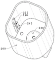
图1为本发明蒸汽消毒器的内部结构示意图,用于展示蒸汽消毒机的内部结构;Fig. 1 is a schematic view of the internal structure of the steam sterilizer of the present invention, for showing the internal structure of the steam sterilizer;
图2为本发明蒸汽消毒器的内部构造简图;Fig. 2 is a schematic diagram of the internal structure of the steam sterilizer of the present invention;
图3为本发明蒸汽消毒器的外观结构示意;Fig. 3 is a schematic view of the appearance structure of the steam sterilizer of the present invention;
图4为本发明蒸汽消毒器的剖视图;Fig. 4 is the sectional view of steam sterilizer of the present invention;
图5为本发明蒸汽消毒器的封口板组件的结构示意图;Fig. 5 is the structural representation of the sealing plate assembly of steam sterilizer of the present invention;
图6为本发明蒸汽消毒器的消毒仓和壳体之间的位置关系示意图;Fig. 6 is a schematic diagram of the positional relationship between the sterilization chamber and the housing of the steam sterilizer of the present invention;
图7为本发明蒸汽消毒器的消毒仓滑动驱动装置和消毒仓之间的位置关系示意图;Fig. 7 is a schematic diagram of the positional relationship between the disinfection chamber sliding drive device and the disinfection chamber of the steam sterilizer of the present invention;
图8为本发明蒸汽消毒器的进气气流导向块的结构示意图;Fig. 8 is a schematic structural view of the intake air flow guide block of the steam sterilizer of the present invention;
图9为本发明蒸汽消毒器的置物桶的结构示意图;Fig. 9 is a schematic structural view of the storage barrel of the steam sterilizer of the present invention;
图10为本发明蒸汽消毒器的夹持组件和置物桶主体之间的位置关系示意图;Fig. 10 is a schematic diagram of the positional relationship between the clamping assembly and the main body of the storage bucket of the steam sterilizer of the present invention;
图11为本发明蒸汽消毒器的夹持组件第一种形态的结构示意图;Fig. 11 is a schematic structural view of the first form of the clamping assembly of the steam sterilizer of the present invention;
图12为本发明蒸汽消毒器的镊子体的结构示意图;Fig. 12 is a schematic structural view of the tweezers body of the steam sterilizer of the present invention;
图13为本发明蒸汽消毒器的夹持组件第二种形态的结构示意图;Fig. 13 is a schematic structural view of the second form of the clamping assembly of the steam sterilizer of the present invention;
图14为本发明蒸汽消毒器的夹持组件第二种形态的原理图;Fig. 14 is a schematic diagram of the second configuration of the clamping assembly of the steam sterilizer of the present invention;
图15为本发明蒸汽消毒器的夹持组件第三种形态的结构示意图;Fig. 15 is a schematic structural view of the third form of the clamping assembly of the steam sterilizer of the present invention;
图16为本发明蒸汽消毒器的夹持组件第三种形态的原理图;Fig. 16 is a schematic diagram of the third configuration of the clamping assembly of the steam sterilizer of the present invention;
图中:In the picture:
壳体100、气体交换孔110、
消毒仓200、蒸汽进气孔210、蒸汽出气孔220、置物桶定位组件230、进气气流导向块240、
消毒仓滑动驱动装置300、Disinfection bin sliding
置物桶400、置物桶主体410、透气孔420、密封元件430、凸出板440、夹持组件450、镊子体451、缓冲软垫4511、第一镊子体4512、第二镊子体4513、镊子体定位组件452、镊子体转动组件453、中心动力仓4531、换向轮4532、导力绳4533、导力绳收放组件4534、夹持动作辅助块454、
封口板组件500、封口板主体510、封口板定位组件520、支撑杆521、定位块522、弹性元件523、盖体530、封口板转动组件540、转动手柄541、辅助轮542;Sealing
具体实施方式Detailed ways
为了便于理解本发明,下面将参照相关附图对本申请进行更全面的描述;附图中给出了本发明的较佳实施方式,但是,本发明可以以许多不同的形式来实现,并不限于本文所描述的实施方式;相反地,提供这些实施方式的目的是使对本发明的公开内容理解的更加透彻全面。In order to facilitate understanding of the present invention, the present application will be described more fully below with reference to the accompanying drawings; preferred embodiments of the present invention are shown in the accompanying drawings, however, the present invention can be realized in many different forms and is not limited to Embodiments described herein; on the contrary, the purpose of providing these embodiments is to make the disclosure of the present invention more thorough and comprehensive.
需要说明的是,本文所使用的术语“垂直”、“水平”、“上”、“下”、“左”、“右”以及类似的表述只是为了说明的目的,并不表示是唯一的实施方式。It should be noted that the terms "vertical", "horizontal", "upper", "lower", "left", "right" and similar expressions used herein are for the purpose of illustration only and do not represent the only implementation Way.
除非另有定义,本文所使用的所有的技术和科学术语与属于本发明的技术领域的技术人员通常理解的含义相同;本文中在本发明的说明书中所使用的术语只是为了描述具体的实施方式的目的,不是旨在于限制本发明;本文所使用的术语“和/或”包括一个或多个相关的所列项目的任意的和所有的组合。Unless otherwise defined, all technical and scientific terms used herein have the same meaning as commonly understood by those skilled in the technical field of the present invention; the terms used in the description of the present invention herein are only to describe specific implementations is not intended to limit the present invention; as used herein, the term "and/or" includes any and all combinations of one or more of the associated listed items.
请参阅图1,为本发明蒸汽消毒器的内部结构示意图;本申请蒸汽消毒器包括壳体100、消毒仓200、消毒仓升降组件300和封口板组件500;本申请通过取消蒸汽消毒器的舱口盖的设置,增设封口板组件500代替舱口盖封闭消毒仓200,封口板组件500定位在蒸汽消毒器的壳体100上,消毒仓200滑动定位在蒸汽消毒器的壳体100内,消毒仓200下方设置消毒仓升降组件300,在开始消毒前,利用消毒仓升降组件300将消毒仓200托举令其紧贴封口板组件500进而封闭消毒仓200。Please refer to Fig. 1, which is a schematic diagram of the internal structure of the steam sterilizer of the present invention; the steam sterilizer of the present application includes a
实施例一Embodiment one
如图1所示,本申请蒸汽消毒器包括壳体100、消毒仓200、消毒仓升降组件300、封口板组件500、干燥装置、供给系统、排出系统、动力组件和控制单元。As shown in FIG. 1 , the steam sterilizer of the present application includes a
所述的壳体100整个蒸汽消毒器的外壳,起到承载蒸汽消毒器各部件的作用,其形状能够是箱体结构;所述的壳体100的侧壁上设置有气体交换孔110,气体交换孔110的数量为两个及以上,用于与所述的供给系统以及排出系统连通进而向所述的消毒仓200输入蒸汽或将消毒仓200内部的气体排出。The shell of the entire steam sterilizer of the
所述的消毒仓200如图1、图7或图8所示,主体为一端开口的空心柱形结构,用于为医疗器械的消毒提供空间;所述的消毒仓200滑动定位在所述的壳体100上,消毒仓200包括蒸汽进气孔210、蒸汽出气孔220和密封元件250;所述的蒸汽进气孔210和蒸汽出气孔220均定位在消毒仓200的侧壁上,分别用于与所述的供给系统以及排出系统相连通;所述的密封元件250定位在所述的消毒仓200上靠近开口的位置,用于在开始消毒时防止蒸汽从消毒仓的开口输出。As shown in Figure 1, Figure 7 or Figure 8, the
优选的,所述的蒸汽进气孔210和蒸汽出气孔220均为长圆孔,与所述的气体交换孔110相配合。Preferably, the
优选的,所述的消毒仓200滑动的方向为蒸汽消毒器的高度方向。Preferably, the sliding direction of the
优选的,所述的密封元件250为橡胶密封垫。Preferably, the sealing
所述的消毒仓滑动驱动装置300定位在所述的消毒仓200和所述的壳体100之间,用于驱动所述的消毒仓200滑动;所述的消毒仓滑动驱动装置300的结构能够是齿轮齿条机构、伸缩杆结构、凸轮机构等。The sterilizing bin sliding
如图3、图4或图5所示,所述的封口板组件500定位在所述的壳体100上,主体为板形,起到在进行消毒时封闭所述的消毒仓200的开口的作用;As shown in FIG. 3, FIG. 4 or FIG. 5, the sealing
进一步的,所述的封口板组件500包括封口板主体510、封口板定位组件520、盖体530和封口板转动组件540;所述的封口板主体510为圆形板或扇形板,其通过所述的封口板定位组件520可转动定位在所述的壳体100上;在蒸汽消毒器运行时,所述的封口板主体510远离所述的消毒仓200的面与所述的壳体100的接触面积大于该面面积的二十六分之一;所述的封口板主体510的轴向与所述的消毒仓200的滑动方向相同;所述的盖体530定位在所述的封口板主体510上,用于将待消毒的医疗器械放入所述的消毒仓200以及在医疗器械消毒完成后从所述的消毒仓200内部取出被消毒的医疗器械;所述的封口板转动组件540起到驱动所述的封口板主体510转动进而改变所述的盖体530相对所述的消毒仓200的空间位置的作用;Further, the sealing
进一步的,如图1和图4所示,所述的封口板定位组件520包括支撑杆521、定位块522和弹性元件523;所述的支撑杆521主体为杆形或柱形,固定在所述的壳体100上;所述的定位块522固定在所述的支撑杆521上,用于定位所述的封口板主体510;所述的封口板主体510可转动连接在所述的定位块522;所述的定位块522和封口板主体510之间定位有弹性元件523,弹性元件523用于在蒸汽消毒器非消毒状态下将所述的封口板主体510顶离所述的壳体100进而便于所述的封口板主体510的转动并借此展示所述的消毒仓200的状态。Further, as shown in Figures 1 and 4, the sealing
进一步的,如图3所示,所述的封口板转动组件540包括转动手柄541和辅助轮542;所述的转动手柄541定位在所述的封口板主体510上;所述的辅助轮542可转动固定在所述的封口板主体510并抵触在所述的壳体100上,辅助轮542的轴向与所述的封口板主体510的轴向相同,用于便于使用人员转动所述的封口板主体510;优选的,所述的辅助轮542的数量为三个。Further, as shown in FIG. 3 , the sealing
如图2所示,所述的干燥装置、供给系统、排出系统、动力组件和控制单元均为现有技术,在此不进行赘述。As shown in FIG. 2 , the drying device, supply system, discharge system, power components and control unit are all in the prior art, and will not be repeated here.
优选的,所述的控制单元包括控制面板,控制面板起到控制设备各部运行的作用。Preferably, the control unit includes a control panel, and the control panel functions to control the operation of each part of the device.
优选的,所述的控制面板上定位有多个控制按键;Preferably, a plurality of control buttons are positioned on the control panel;
优选的,所述的控制面板为触控屏;Preferably, the control panel is a touch screen;
本申请实施例的使用步骤依次为:操作人员转动所述的封口板主体510,令所述的盖体530转动至所述的消毒仓200的正上方;打开所述的盖体530,向所述的消毒仓200内部放置待消毒的医疗器械;转动所述的封口板主体510直至从所述的盖体530中看不到所述的消毒仓200的开口;操作人员通过所述的控制单元控制所述的消毒仓滑动驱动装置300运行,使所述的消毒仓200的开口上的密封组件250紧贴所述的封口板主体510;通过所述的控制单元控制所述的供给系统和排出系统运行,开始消毒;消毒结束后停运所述的供给系统和排出系统,运行所述的消毒仓滑动驱动装置300,令所述的消毒仓200远离所述的封口板主体510;转动所述的封口板主体510,令所述的盖体530转动至所述的消毒仓200的正上方,打开所述的盖体530,取出消毒完成的医疗器械。The steps of using the embodiment of the present application are as follows: the operator rotates the
上述本申请实施例中的技术方案,至少具有如下的技术效果或优点:The above-mentioned technical solutions in the embodiments of the present application have at least the following technical effects or advantages:
解决了蒸汽消毒器工作过程中容易损坏舱口盖及其定位组件进而造成安全隐患的技术问题,实现了蒸汽消毒器的稳定可靠运行的技术效果。It solves the technical problem that the hatch cover and its positioning components are easily damaged during the working process of the steam sterilizer, thereby causing potential safety hazards, and realizes the technical effect of stable and reliable operation of the steam sterilizer.
实施例二Embodiment two
考虑到放入所述的消毒仓200内部的医疗器械的部分面会与所述的消毒仓200的内壁贴合从而影响杀菌消毒效果;本实施例在上述实施例的基础上增设了置物桶400用于安置被消毒的医疗器械。Considering that part of the surface of the medical device put into the
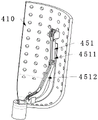
如图1、图6和图9所示,所述的置物桶400通过置物桶定位组件230定位在所述的消毒仓200内部,置物桶400包括置物桶主体410,置物桶主体410为桶形,其上密布有透气孔420。As shown in Figure 1, Figure 6 and Figure 9, the
考虑到靠近所述的蒸汽进气孔210的医疗器械和远离蒸汽进气孔210的医疗器械与蒸汽的接触程度以及受热程度均不同,影响消毒的进行;针对此问题,如图8和图9所示,本实施例令所述的置物桶400通过置物桶定位组件230可转动固定连接在所述的消毒仓200上,并在所述的置物桶主体410外壁上增设凸出板440,在消毒仓200的内壁上靠近所述的蒸汽进气孔210的位置增设进气气流导向块240;在高压蒸汽经所述的蒸汽进气孔210并在所述的进气气流导向块240的导向下进入所述的消毒仓200,吹向所述的凸出板440进而推动所述的置物桶400转动进而使置物桶400内部的医疗器械均匀杀菌。Considering that the medical devices close to the
上述本申请实施例中的技术方案,至少具有如下的技术效果或优点:The above-mentioned technical solutions in the embodiments of the present application have at least the following technical effects or advantages:
进一步的增强了杀菌效果,一定程度上缩短了消毒所需时间。The bactericidal effect is further enhanced, and the time required for disinfection is shortened to a certain extent.
实施例三Embodiment Three
考虑到实施例二中伴随着所述的置物桶400的转动,其内部的被消毒医疗器械容易发生位移,产生碰撞进而产生设备运行噪音,损伤被消毒医疗器械的同时也容易对所述的置物桶400造成损坏。Considering that with the rotation of the
本实施例在上述实施例的基础上增设了夹持组件450,所述的夹持组件450定位在所述的置物桶主体410的内壁上,起到定位放置在所述的置物桶400内的医疗器械的作用;In this embodiment, on the basis of the above embodiments, a clamping
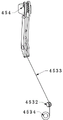
进一步的,如图10、图11和图12所示,所述的夹持组件450包括镊子体451、镊子体定位组件452、镊子体转动组件453和夹持动作辅助块454;Further, as shown in FIG. 10 , FIG. 11 and FIG. 12 , the clamping
所述的镊子体451主体为“V”字形,用于夹取进而定位被消毒医疗器械,镊子体451通过所述的镊子体定位组件452可转动固定连接在所述的置物桶主体410上;所述的镊子体转动组件453用于驱动所述的镊子体451转动进而与所述的夹持动作辅助块454配合实现待消毒医疗器械的夹取;所述的夹持动作辅助块454主体为“V”字形,当所述的镊子体451转动时镊子体451与所述的夹持动作辅助块454接触进而被挤压进而实现夹取动作。The main body of the
进一步的,所述的镊子体转动组件453包括中心动力仓4531、换向轮4532、导力绳4533和导力绳收放组件4534;所述的中心动力仓4531可转动固定连接在所述的置物桶400上并定位在所述的置物桶定位组件230上,中心动力仓4531主体为空心圆柱形,其轴向与所述的置物桶400的轴向相同;所述的换向轮4532定位在所述的中心动力仓4531的侧壁上,用于为所述的导力绳4533导向;所述的导力绳收放组件4534定位在所述的中心动力仓4531中,起到收放所述的导力绳4533进而控制所述的镊子体451转动的作用;所述的导力绳4533一端定位在所述的镊子体451上,另一端缠绕定位在所述的导力绳收放组件4534上。Further, the tweezers
优选的,如图12所示,所述的镊子体451上定位有缓冲软垫4511,所述的缓冲软垫4511起到减少医疗器械磨损并保证夹持牢固性的作用。Preferably, as shown in FIG. 12 , a
优选的,所述的夹持组件450的运行为手动控制夹紧与放松或受控于所述的控制单元。Preferably, the operation of the clamping
本申请实施例实际运行时,打开所述的盖体530,向所述的消毒仓200内部放置待消毒的医疗器械,利用所述的夹持组件450定位各个放置在所述的消毒仓200内部的待消毒医疗器械;取出消毒后的医疗器械时,首先解除所述的夹持组件450对医疗器械的定位。During the actual operation of the embodiment of the present application, open the
实施例四Embodiment four
考虑到上述实施例实际应用时,被固定的医疗器械与所述的镊子体451直接接触的位置可能出现消毒不够彻底的问题,影响整体消毒效果;本实施例在上述实施例的基础上对所述的夹持组件450做了相关改进,具体为:Considering that in the actual application of the above-mentioned embodiment, the position where the fixed medical device is in direct contact with the
如图13和图14所示,所述的镊子体451主体为“X”形,所述的夹持动作辅助块454的数量为两个,夹持动作辅助块454均定位在所述的置物桶主体410的内壁上且空间位置上位于所述的夹持动作辅助块454靠近所述的镊子体451的两端;所述的夹持组件450还包括罩板4535,罩板4535定位在所述的置物桶主体410的内壁上,用于定位所述的换向轮4532;所述的镊子体定位组件452用于定位所述的镊子体451,所述的镊子体转动组件453起到驱动所述的镊子体451转动的作用。As shown in Figure 13 and Figure 14, the main body of the
优选的,所述的镊子体451的数量为多个,规格有多种,用于定位不用的医疗器械。Preferably, the number of the
本申请实施例实际运行时,在消毒过程中,所述的控制单元控制所述的镊子体转动组件453运行,循环的对正在消毒的医疗器械夹紧与放松。During the actual operation of the embodiment of the present application, during the disinfection process, the control unit controls the operation of the tweezers
实施例五Embodiment five
实验时发现实施例四中的所述的镊子体451在转动过程中容易出现对正在消毒的医疗器械固定不牢靠的问题,进而医疗器械松脱给消毒带来不利影响;During the experiment, it was found that the
针对上述问题,如图15和图16所示,本实施例在实施例四的基础上将单个所述的镊子体451拆分为两个非同步转动的镊子体451,分别为第一镊子体4512和第二镊子体4513,并对所述的镊子体转动组件453做适应性改造,使所述的第一镊子体4512和第二镊子体4513异步夹紧。In view of the above problems, as shown in Figure 15 and Figure 16, this embodiment splits the
本申请实施例实际运行时,在消毒过程中,所述的控制单元控制所述的镊子体转动组件453运行,所述的第一镊子体4512和第二镊子体4513循环的对正在消毒的医疗器械夹紧与放松;在消毒进行过程的任一时刻,所述的第一镊子体4512和第二镊子体4513至少有一个处于夹紧状态。During the actual operation of the embodiment of the present application, during the disinfection process, the control unit controls the operation of the tweezers
以上所述仅为本发明的优选实施方式,并不用于限制本发明,对于本领域技术人员来说,本发明可以有各种更改和变化。凡在本发明精神和原则内,所做的任何修改、等同替换、改进等,均应包含在本发明的保护范围之内。The above descriptions are only preferred embodiments of the present invention, and are not intended to limit the present invention. For those skilled in the art, the present invention may have various modifications and changes. Any modifications, equivalent replacements, improvements, etc. made within the spirit and principles of the present invention shall be included within the protection scope of the present invention.
Claims (8)
Priority Applications (1)
| Application Number | Priority Date | Filing Date | Title |
|---|---|---|---|
| CN202110416777.6A CN112972713B (en) | 2021-04-19 | 2021-04-19 | a steam sterilizer |
Applications Claiming Priority (1)
| Application Number | Priority Date | Filing Date | Title |
|---|---|---|---|
| CN202110416777.6A CN112972713B (en) | 2021-04-19 | 2021-04-19 | a steam sterilizer |
Publications (2)
| Publication Number | Publication Date |
|---|---|
| CN112972713A CN112972713A (en) | 2021-06-18 |
| CN112972713B true CN112972713B (en) | 2022-11-18 |
Family
ID=76341028
Family Applications (1)
| Application Number | Title | Priority Date | Filing Date |
|---|---|---|---|
| CN202110416777.6A Expired - Fee Related CN112972713B (en) | 2021-04-19 | 2021-04-19 | a steam sterilizer |
Country Status (1)
| Country | Link |
|---|---|
| CN (1) | CN112972713B (en) |
Citations (4)
| Publication number | Priority date | Publication date | Assignee | Title |
|---|---|---|---|---|
| GB191502990A (en) * | 1915-02-24 | 1915-12-16 | William Phillips Thompson | Improvements in and relating to Apparatus for Sterilizing Instruments, Vessels, Suture Material, and the like in Boiling Water. |
| CN104080484A (en) * | 2012-06-06 | 2014-10-01 | 绝对向上有限责任公司 | A steriliser |
| CN109078205A (en) * | 2018-11-08 | 2018-12-25 | 自贡德西玛医疗设备有限公司 | A kind of new medical bactericidal unit |
| CN211111977U (en) * | 2019-08-06 | 2020-07-28 | 苏州新格诺康生物技术有限公司 | Degassing unit for fermentation cylinder |
Family Cites Families (3)
| Publication number | Priority date | Publication date | Assignee | Title |
|---|---|---|---|---|
| JPH06142163A (en) * | 1992-11-09 | 1994-05-24 | Morita Mfg Co Ltd | High-pressure steam sterilizer |
| AT516399B1 (en) * | 2015-03-20 | 2016-05-15 | Meteka Gmbh | Device for heating, disinfecting and / or sterilizing a product under overpressure |
| KR101879932B1 (en) * | 2016-05-11 | 2018-07-18 | 최종율 | High Temperature and High Pressure Sterilizer |
-
2021
- 2021-04-19 CN CN202110416777.6A patent/CN112972713B/en not_active Expired - Fee Related
Patent Citations (4)
| Publication number | Priority date | Publication date | Assignee | Title |
|---|---|---|---|---|
| GB191502990A (en) * | 1915-02-24 | 1915-12-16 | William Phillips Thompson | Improvements in and relating to Apparatus for Sterilizing Instruments, Vessels, Suture Material, and the like in Boiling Water. |
| CN104080484A (en) * | 2012-06-06 | 2014-10-01 | 绝对向上有限责任公司 | A steriliser |
| CN109078205A (en) * | 2018-11-08 | 2018-12-25 | 自贡德西玛医疗设备有限公司 | A kind of new medical bactericidal unit |
| CN211111977U (en) * | 2019-08-06 | 2020-07-28 | 苏州新格诺康生物技术有限公司 | Degassing unit for fermentation cylinder |
Also Published As
| Publication number | Publication date |
|---|---|
| CN112972713A (en) | 2021-06-18 |
Similar Documents
| Publication | Publication Date | Title |
|---|---|---|
| EP1346735B1 (en) | Ultraviolet pasteurizer | |
| JP5694964B2 (en) | Gas sterilization apparatus and gas sterilization method | |
| CN110662606B (en) | Safety cabinet and sterilization method thereof | |
| JP6271224B2 (en) | Incubator and incubator decontamination method | |
| CN103118581A (en) | adjust medical equipment | |
| CN110639042B (en) | Uropoiesis surgery is with multi-functional disinfecting equipment | |
| CN112972713B (en) | a steam sterilizer | |
| KR101879932B1 (en) | High Temperature and High Pressure Sterilizer | |
| CN206153219U (en) | Disposable medical instrument processing apparatus of portable non - | |
| CN207745206U (en) | A kind of operation device cleaning disinfection device | |
| CN107412806A (en) | Surgical instrument cleaning tool storage disinfect box | |
| CN113144231B (en) | a medical sterilizer | |
| CN211188386U (en) | Portable medical instrument disinfection device | |
| CN114101170A (en) | Instrument cleaning and sterilizing device for nursing of supply room | |
| CN213670844U (en) | Ultrasonic cleaning and sterilizing device for obstetrics and gynecology department | |
| KR200227390Y1 (en) | ozone stealthily | |
| CN220090022U (en) | Disinfection and sterilization equipment with built-in rotating object rack | |
| CN114668872A (en) | A medical device storage and sterilization device | |
| CN111603583A (en) | Disinfection and sterilization nursing device for supply room for preventing nosocomial infection | |
| JP6663880B2 (en) | Glove sterilization support member and isolator | |
| JP6145050B2 (en) | Endoscope storage | |
| CN222854281U (en) | A medical equipment disinfection cabinet and a multifunctional cleaning and disinfection device | |
| CN220125156U (en) | Laboratory instrument cleaning equipment | |
| CN111569126A (en) | A sterilization device for epidemic prevention equipment | |
| CN213553995U (en) | Surgery medical instrument sterilizer convenient to accomodate |
Legal Events
| Date | Code | Title | Description |
|---|---|---|---|
| PB01 | Publication | ||
| PB01 | Publication | ||
| SE01 | Entry into force of request for substantive examination | ||
| SE01 | Entry into force of request for substantive examination | ||
| CB03 | Change of inventor or designer information | ||
| CB03 | Change of inventor or designer information |
Inventor after: Liu Xiaojing Inventor after: Zhang Haiping Inventor after: Hou Jingtao Inventor after: Zhao Changyu Inventor before: Zhao Changyu |
|
| TA01 | Transfer of patent application right | ||
| TA01 | Transfer of patent application right |
Effective date of registration: 20221101 Address after: 710061 No. 277, Yanta West Road, Shaanxi, Xi'an Applicant after: THE FIRST AFFILIATED HOSPITAL OF MEDICAL COLLEGE OF XI'AN JIAOTONG University Address before: 2 / F, building 6, courtyard 19, Tianrong street, Daxing biomedical industrial base, Zhongguancun Science and Technology Park, Daxing District, Beijing Applicant before: Zhao Changyu |
|
| GR01 | Patent grant | ||
| GR01 | Patent grant | ||
| CF01 | Termination of patent right due to non-payment of annual fee | ||
| CF01 | Termination of patent right due to non-payment of annual fee |
Granted publication date: 20221118 |