CN113424112B - Month and leap year display mechanism for a timepiece - Google Patents

Month and leap year display mechanism for a timepiece Download PDF

Info

Publication number
CN113424112B
CN113424112B CN202080014615.3A CN202080014615A CN113424112B CN 113424112 B CN113424112 B CN 113424112B CN 202080014615 A CN202080014615 A CN 202080014615A CN 113424112 B CN113424112 B CN 113424112B
Authority
CN
China
Prior art keywords
month
display
wheel
wheel set
leap year
Prior art date
Legal status (The legal status is an assumption and is not a legal conclusion. Google has not performed a legal analysis and makes no representation as to the accuracy of the status listed.)
Active
Application number
CN202080014615.3A
Other languages
Chinese (zh)
Other versions
CN113424112A (en
Inventor
T·布朗
Current Assignee (The listed assignees may be inaccurate. Google has not performed a legal analysis and makes no representation or warranty as to the accuracy of the list.)
Glashuetter Uhrenbetrieb GmbH
Original Assignee
Glashuetter Uhrenbetrieb GmbH
Priority date (The priority date is an assumption and is not a legal conclusion. Google has not performed a legal analysis and makes no representation as to the accuracy of the date listed.)
Filing date
Publication date
Application filed by Glashuetter Uhrenbetrieb GmbH filed Critical Glashuetter Uhrenbetrieb GmbH
Publication of CN113424112A publication Critical patent/CN113424112A/en
Application granted granted Critical
Publication of CN113424112B publication Critical patent/CN113424112B/en
Active legal-status Critical Current
Anticipated expiration legal-status Critical

Links

Images

Classifications

    • GPHYSICS
    • G04HOROLOGY
    • G04BMECHANICALLY-DRIVEN CLOCKS OR WATCHES; MECHANICAL PARTS OF CLOCKS OR WATCHES IN GENERAL; TIME PIECES USING THE POSITION OF THE SUN, MOON OR STARS
    • G04B19/00Indicating the time by visual means
    • G04B19/24Clocks or watches with date or week-day indicators, i.e. calendar clocks or watches; Clockwork calendars
    • G04B19/243Clocks or watches with date or week-day indicators, i.e. calendar clocks or watches; Clockwork calendars characterised by the shape of the date indicator
    • G04B19/247Clocks or watches with date or week-day indicators, i.e. calendar clocks or watches; Clockwork calendars characterised by the shape of the date indicator disc-shaped
    • G04B19/253Driving or releasing mechanisms
    • G04B19/25333Driving or releasing mechanisms wherein the date indicators are driven or released mechanically by a clockwork movement
    • G04B19/25353Driving or releasing mechanisms wherein the date indicators are driven or released mechanically by a clockwork movement driven or released stepwise by the clockwork movement
    • GPHYSICS
    • G04HOROLOGY
    • G04BMECHANICALLY-DRIVEN CLOCKS OR WATCHES; MECHANICAL PARTS OF CLOCKS OR WATCHES IN GENERAL; TIME PIECES USING THE POSITION OF THE SUN, MOON OR STARS
    • G04B19/00Indicating the time by visual means
    • G04B19/24Clocks or watches with date or week-day indicators, i.e. calendar clocks or watches; Clockwork calendars
    • G04B19/243Clocks or watches with date or week-day indicators, i.e. calendar clocks or watches; Clockwork calendars characterised by the shape of the date indicator
    • G04B19/247Clocks or watches with date or week-day indicators, i.e. calendar clocks or watches; Clockwork calendars characterised by the shape of the date indicator disc-shaped
    • GPHYSICS
    • G04HOROLOGY
    • G04BMECHANICALLY-DRIVEN CLOCKS OR WATCHES; MECHANICAL PARTS OF CLOCKS OR WATCHES IN GENERAL; TIME PIECES USING THE POSITION OF THE SUN, MOON OR STARS
    • G04B19/00Indicating the time by visual means
    • G04B19/24Clocks or watches with date or week-day indicators, i.e. calendar clocks or watches; Clockwork calendars
    • G04B19/243Clocks or watches with date or week-day indicators, i.e. calendar clocks or watches; Clockwork calendars characterised by the shape of the date indicator
    • G04B19/247Clocks or watches with date or week-day indicators, i.e. calendar clocks or watches; Clockwork calendars characterised by the shape of the date indicator disc-shaped
    • G04B19/253Driving or releasing mechanisms
    • GPHYSICS
    • G04HOROLOGY
    • G04BMECHANICALLY-DRIVEN CLOCKS OR WATCHES; MECHANICAL PARTS OF CLOCKS OR WATCHES IN GENERAL; TIME PIECES USING THE POSITION OF THE SUN, MOON OR STARS
    • G04B47/00Time-pieces combined with other articles which do not interfere with the running or the time-keeping of the time-piece
    • G04B47/06Time-pieces combined with other articles which do not interfere with the running or the time-keeping of the time-piece with attached measuring instruments, e.g. pedometer, barometer, thermometer or compass
    • GPHYSICS
    • G04HOROLOGY
    • G04BMECHANICALLY-DRIVEN CLOCKS OR WATCHES; MECHANICAL PARTS OF CLOCKS OR WATCHES IN GENERAL; TIME PIECES USING THE POSITION OF THE SUN, MOON OR STARS
    • G04B19/00Indicating the time by visual means
    • G04B19/24Clocks or watches with date or week-day indicators, i.e. calendar clocks or watches; Clockwork calendars
    • G04B19/243Clocks or watches with date or week-day indicators, i.e. calendar clocks or watches; Clockwork calendars characterised by the shape of the date indicator
    • G04B19/247Clocks or watches with date or week-day indicators, i.e. calendar clocks or watches; Clockwork calendars characterised by the shape of the date indicator disc-shaped
    • G04B19/253Driving or releasing mechanisms
    • G04B19/25333Driving or releasing mechanisms wherein the date indicators are driven or released mechanically by a clockwork movement
    • GPHYSICS
    • G04HOROLOGY
    • G04BMECHANICALLY-DRIVEN CLOCKS OR WATCHES; MECHANICAL PARTS OF CLOCKS OR WATCHES IN GENERAL; TIME PIECES USING THE POSITION OF THE SUN, MOON OR STARS
    • G04B19/00Indicating the time by visual means
    • G04B19/24Clocks or watches with date or week-day indicators, i.e. calendar clocks or watches; Clockwork calendars
    • G04B19/243Clocks or watches with date or week-day indicators, i.e. calendar clocks or watches; Clockwork calendars characterised by the shape of the date indicator
    • G04B19/247Clocks or watches with date or week-day indicators, i.e. calendar clocks or watches; Clockwork calendars characterised by the shape of the date indicator disc-shaped
    • G04B19/253Driving or releasing mechanisms
    • G04B19/25333Driving or releasing mechanisms wherein the date indicators are driven or released mechanically by a clockwork movement
    • G04B19/25353Driving or releasing mechanisms wherein the date indicators are driven or released mechanically by a clockwork movement driven or released stepwise by the clockwork movement
    • G04B19/25366Driving or releasing mechanisms wherein the date indicators are driven or released mechanically by a clockwork movement driven or released stepwise by the clockwork movement manually corrected at the end of months having less than 31 days

Landscapes

  • Physics & Mathematics (AREA)
  • General Physics & Mathematics (AREA)
  • Electromechanical Clocks (AREA)

Abstract

一种用于钟表(1000)的显示机构(10),该显示机构(10)具有集成在月份显示装置中的闰年显示装置,并且包括控制机构(3),该控制机构每月围绕轴线(D)驱动月份显示轮副(2)一次,该月份显示轮副(2)布置在表盘(1)下方,具有在一个象限中的月份窗口(1C),该月份窗口仅允许显示月份显示轮副(2)的四分之一,该月份显示轮副(2)四年转动一圈,并在90°的角扇区上带有至少一个特征性的闰年标记,并且承载标示器,其中每个标示器设置为指示表盘(1)的静态月份刻度上的一个月份,或承载等距的月份标记,其中表盘(1)的固定标志指向这些月份标记之一。

Figure 202080014615

A display mechanism (10) for a timepiece (1000), the display mechanism (10) having a leap year display device integrated in a month display device, and comprising a control mechanism (3) that surrounds an axis (D) monthly ) once drives the month display wheel set (2), which is arranged below the dial (1), with a month window (1C) in one quadrant, which allows only the month display wheel set (1C) to be displayed ( 2), the month showing the wheel set (2) rotates once every four years, with at least one characteristic leap year marking on an angular sector of 90°, and carrying markers, each of which The device is set to indicate a month on the static month scale of the dial (1), or to carry equally spaced month marks, with the fixed mark of the dial (1) pointing to one of these month marks.

Figure 202080014615

Description

Month and leap year display mechanism for a timepiece
Technical Field
The invention relates to a month and leap year display mechanism for a timepiece.
The invention concerns the field of timepiece complexities including a calendar.
Background
The calendar mechanism is one of the classic complex mechanisms of timepieces. Some sophisticated organizations are able to manage durations of months or years. The leap year display or indicator allows the user to determine whether the current year is a leap year and, depending on the complexity of the watch, can manage the display of the last day of february and the correct change to the first day of march.
In the case of the simplest calendar mechanism, the user is allowed to correct the display of the last few days of the month, usually by means of a control stem, as long as it is known whether the current year is a leap year. The mechanisms differ as to whether they relate to a simple date calendar, an annual calendar or a perpetual calendar. In these latter cases, the leap year control mechanism requires expensive components, such as a maltese cross cam, and takes up a certain amount of space inside the watch case or timepiece case (if it is stationary like a clock).
Leap year displays are typically implemented by displaying a sector of a disk with four quadrants within a small window, or by the cooperation of a marker (index) with a portion of such a disk.
WO patent No.01/48568 in the name of belhanorm discloses a perpetual calendar mechanism actuated by a motorized wheel of a timepiece movement and displaying at least a calendar date. It comprises only a rotary movable element formed by a gear wheel and the driving wheel rotates one revolution at the midnight instant each day. One of the gears is a date wheel which drives a movable element displaying the date. The date wheel comprises thirty-one teeth and is driven at a rate of one step per day by a drive tooth integral with the drive wheel. At least one of the other gears is a movable element for a length of several months, able to be driven by a control wheel integral with the date wheel during the last four days of a month; this movable element for a length of months comprises a series of teeth consisting of a series of 0 to 3 sets of teeth, each set corresponding to a month of the year. The date wheel is driven to travel at the end of a month of 31 days by a number of steps corresponding to the difference between 31 and the number of days of the month to which the regulating clockwork train is concerned, the regulating clockwork train comprising at least one drive pinion integral with the drive wheel, a movable element for the duration of the month, a date drive pinion and a control wheel.
Disclosure of Invention
The invention proposes to combine the display of the current month with the display of the current year (leap or non-leap years) using a very simple, inexpensive, very reliable, easily calibrated mechanism, which is limited to the reasonable space inside the timepiece involved.
To this end, the invention relates to a month and leap year display mechanism for a timepiece, wherein the month and leap year display mechanism comprises a leap year display device integrated in the month display device, the month and leap year display mechanism comprising or being arranged to cooperate with a movement arranged to drive a month display wheel set, via a control mechanism comprised in the month and leap year display mechanism, which rotates about an axis of rotation and is arranged below a cover plate or below a dial, and wherein a month window comprised in a 90 ° angular sector about the axis of rotation is arranged to allow a user to see one quarter of the month display wheel set, the other three quarters of which are hidden from the user, and wherein the control mechanism is arranged to turn the month display wheel set one full turn in four years, and wherein the month display wheel set carries at least one characteristic leap year mark on an angular sector of 90 ° and carries indicators, each of which is arranged to indicate one month on a static month scale of the dial, or carries equidistant month marks, with the fixed index of the dial pointing to one of these month marks, the month and leap year display mechanism being characterized in that the control mechanism comprises an input wheel set arranged to be driven by the hour wheel of the movement or by a train of wheels meshing with the hour wheel or by a date mechanism, the input wheel set comprising a finger arranged to pivot a first star wheel integral with an intermediate wheel meshing with a changeover train of wheels to drive a stop wheel comprising a recess arranged to cooperate with a pawl reset by a spring towards a rest position, the stop wheel is integral with a second star wheel, the teeth of which are arranged: when the stop wheel is pivoted, the tooth drives a pin comprised in the month display wheel set; and the teeth hold the pin in place when the detent wheel is held stationary by the pawl without pivoting of the first star wheel.
The invention also relates to a calendar mechanism comprising a date mechanism arranged to cooperate with a timepiece movement, and comprising at least one such month and leap year display mechanism.
The invention also relates to a timepiece comprising at least one timepiece movement arranged to drive at least one such month and leap year display mechanism and/or at least one such calendar mechanism.
Drawings
Other features and advantages of the present invention will become apparent upon reading the following detailed description and upon reference to the drawings in which:
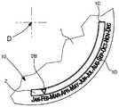
fig. 1 schematically shows, in plan view, a watch comprising a calendar mechanism including a date mechanism that displays the date in a date window near a third o ' clock, close to the control stem of the watch, and a month and leap year display mechanism according to the invention, which, in a first variant, comprises a month display window extending over the quadrant between third o ' clock and sixth o ' clock, with a static month scale extending along the month window on the dial, and a month display wheel set comprising a circular track carrying four different indicators, each indicator appearing in the window for only one year and pointing to the name of the current month; the figure shows a marker dedicated to leap years pointing to february currently.
Fig. 2 shows, in a manner similar to fig. 1, the details of the same watch in the usual year: the ordinary year indicator replaces the special leap year indicator of fig. 1 and points to february of the current year.
Fig. 3 to 6 show the control mechanism of the month display wheel set.
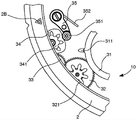
Fig. 3 shows, in a manner similar to fig. 1, the entire month display wheel set carrying four triangular markers, one of which, in the vicinity of six o' clock, is a leap year indicator, unlike the other three, and the cooperation of this month display wheel set with the control mechanism.
Figure 4 is a detailed view of the control mechanism near the bottom of the moon, the control mechanism being an input at input wheel set 31, input wheel set 31 being arranged to be driven by the movement or date mechanism and having fingers arranged to pivot a first star wheel driving a stop wheel via a gear train; the detent wheel comprises a recess arranged to cooperate with a pawl which is returned by a spring towards the rest position, and is integral with a second star wheel arranged to: the pins of the month display wheel set are driven when the detent wheel is pivoted, and are held in position when the detent wheel is held stationary by the pawl without pivoting the first star wheel.
Fig. 5 is similar to fig. 4, showing the state of the control mechanism on the eighth day of the month.
Fig. 6 is similar to fig. 4, showing the state of the control mechanism on the last day of a month just before midnight and before the second star wheel jumps to drive the month display wheel set.
Figures 7 and 9 show a second variant in which the month display wheel set bears lower indicia and the month window has an at least partially translucent lens (crystal) bearing twelve translucent upper indicia, each corresponding to one month of the year; the month display wheel set rotates under the lens, the four lower marks being equidistant and colored and/or reflective reveal marks, each lower mark having an angular amplitude of one month mark.
Fig. 7 shows said lens and the month display wheel set, respectively.
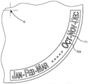
Fig. 8 shows the superposition of the lenses and of the month display wheel sets in march of ordinary, non-leap years, during which the lower marks with hatching dedicated to the ordinary year can be seen through the openings of the letters of the march.
Fig. 9 shows the superposition of the lenses and of the month display wheel set in the month of february in leap years, during which the lower meshed indicia specific to leap years are visible through the openings of the letters of february.
Fig. 10 shows a third variant in which the month display wheel set carries forty-eight equidistant month indicia corresponding to a series of months of the four years, and one fixed sign on the dial, which is a marker and/or a tinted translucent lens, points to one of the month indicia corresponding to the current month; of these forty-eight month indicia, twelve consecutive indicia are leap year month indicia and are different from the other thirty-six indicia, which are month indicia of the common year; the figure shows a non-limiting example in which the month names of the month marks of the ordinary years are represented by thin letters, while the month marks of the leap years are represented by thicker letters, in which the current february of the ordinary year is visible under a translucent tinted lens, which itself faces a fixed indicator on the dial.
Figures 11 to 13 show one example of a correction mechanism that can be used with each of these three variants.
Fig. 11 shows, in a manner similar to fig. 3, the whole month display wheel set of the first variant, and the cooperation of this month display wheel set with the control mechanism and the month correction mechanism close to the stem at three o' clock.
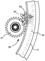
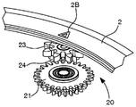
Fig. 12 and 13 are a plan view and a perspective view, respectively, showing details of a correction wheel arranged to move a correction pinion integral with a correction star wheel arranged to drive the pin of the month display wheel set at the end of the month in the same way as the second star wheel.
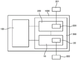
Fig. 14 is a block diagram representing a timepiece, in particular a wristwatch, comprising a movement, a calendar mechanism with a date mechanism and its date corrector mechanism, and a month and leap year display mechanism according to the invention with its month corrector.
Detailed Description
The invention relates to a month and leap year display mechanism 10 for a timepiece 1000. Fig. 1 shows one such timepiece 1000, here a watch, comprising a conventional time display 1A via an hour hand and a minute hand, a date mechanism 200 with a date display 1B, in particular a control stem 221 controlling a date corrector 220, and a month and leap year display mechanism 10 according to the invention.
According to the invention, the mechanism 10 comprises a leap year display integrated in the month display. The invention is described in the specific non-limiting case of a gregory calendar display device, but is fully applicable to other types of calendars, in particular of the lunar or twelve constellation type, and the person skilled in the art will know how to apply by: i.e. by replacing the means for changing the display at the end of the month described below with means for changing the display at the end of the month of the lunar month or at the end of any particular period.
Depending on the configuration of the timepiece, mechanism 10 either includes movement 100 or mechanism 10 is arranged to cooperate with movement 100. In both cases, this movement 100 is arranged to drive, via a control mechanism 3 included in the mechanism 10, a month display wheel set 2, this month display wheel set 2 being formed in particular, but not exclusively, by a display ring or a display disc. The month display wheel set 2 is provided to rotate about a rotation axis D and is arranged below the cover plate or below the dial 1. The dial 1 or cover plate, for example a bridge or the like, comprises a month window 1C, the month window 1C being contained within an angular sector of 90 ° around the rotation axis D. The month window 1C is arranged to allow the user to see one quarter of the month display disc 2, while the remaining three quarters of the month display disc 2 are hidden from the user by the dial 1 and/or at least one fixed part of the timepiece 100.
According to the invention, the control mechanism 3 is arranged to rotate the month display wheel set 2 one revolution in four years. Thus, the month display wheel set 2 rotates by forty-eight times at the end of each month.
The month display wheel set 2 carries at least one characteristic leap year mark on an angular sector of 90 °.
The month display wheel set 2 carries indicators which are each arranged to indicate one month on a static month scale of the dial 1, or the month display wheel set 2 carries equidistant month indicia, wherein one fixed sign of the dial 1 points to one of the month indicia.
The figures show the design of such a leap year display, which in this particular non-limiting version comprises a cover plate, in particular in the form of a dial 1, of a month display wheel set 2, the month display wheel set 2 being a ring or a disk carrying a ring-shaped display track, and a control and dispensing mechanism 3. The month display wheel set 2 is mounted to pivot about an axis of rotation D. The control mechanism 3 driven by the movement 100 or the date mechanism 200 has the following functions: driving the month display wheel set 2 by an angular pitch at each month change and returning the month wheel set 2 to the new rest position until it is actuated at the end of the next month.
In a first variant, as shown in fig. 1 and 2, the month and leap year display mechanism 10 comprises a month window 1C facing a static month scale 1D of dial 1, this month scale 1D comprising the names of a series of different months. More specifically, the month scale 1D extends at a central angle of 90 ° with respect to the rotation axis D. The month display wheel set 2 comprises a display track which is visible through the month window 1C and comprises four equidistant markers 2A or 2B, of which only one is visible through the month window 1C at a time and always points to the mark on the month scale 1D corresponding to the current month. More specifically, among these indicators, one is a leap year indicator 2A and the other three are ordinary year indicators 2B, the leap year indicator 2A including a visible mark indicating to the user that the year is a leap year. This leap year indicator 2A, which is different from the ordinary year indicator 2B, can therefore be integrated in the month display.
In the figure, these markers are triangular and the leap year markers 2A carry the letter S (from german "Schaltjahr") representing the leap year.
In a particular embodiment, the ordinary year markers 2B are different from each other, each ordinary year marker 2B comprising a numerical indication visible to the user of the number of years from the next leap year.
In another particular embodiment, the ordinary year indicators 2B are different from each other, each including a numerical indication of the number of years passed since the last leap year, visible to the user.
In a second variant, as shown in fig. 7 to 9, the month window 1C comprises a fixed, at least partially translucent lens 70 with twelve static, translucent upper marks 71, each upper mark 71 corresponding to a month of the year. The month display wheel set 2 rotates under this lens 70. The month display wheel set 2 is provided with four lower marks 72A and 72B, these lower marks 72A and 72B being equidistant and visible marks, in particular colored and/or reflective marks, each having an angular amplitude of one month mark 71. Each of the lower marks 72A or 72B is arranged as: the name of the current month is revealed by a partial overlap of the lower mark 72A or 72B concerned with the upper mark 71 of the current month, with a visual contrast with the upper marks 71 of the other months. One of the lower indicia 72 is a leap year lower indicia 72A which is different from the other lower indicia 72, which is a common year lower indicia 72B and is arranged to produce a different visual effect for the user for the current month than for the other months of the year. The four lower indicia 72A and 72B may be formed of colored surfaces that distinguish between the leap year lower indicia 72A and the plain year lower indicia 72B and that may be visible through the outline of the upper indicia 71 or through a different colored reflective surface or otherwise. The outline of the upper mark 71 makes visible the surface of the display wheel set 2, thus revealing only the name (or symbol) of the current month. Figures 7 to 9 show a non-limiting example in which the leap year lower indicia 72A has a cross hatching and the plain year lower indicia 72B has a simple hatching; fig. 8 shows the display of march in the ordinary year, while fig. 9 shows month of october in the leap year. In a particular embodiment, the lens 70 may be transparent only at the upper mark 71, for example inside the letters of the month name, as shown in fig. 8 and 9.
In a third variant, as shown in fig. 10, the month display wheel set 2 carries equidistant month indicia 80 corresponding to a series of months of the year four, and one fixed sign 83 of the dial 1 is directed towards one of the month indicia 80, this fixed sign 83 being a marker 84 and/or a tinted translucent lens 85. These month indicia 80 consist of forty-eight month indicia 81 and 82, of which the twelve consecutive indicia are leap year month indicia 81 and are different from the other thirty-six month indicia 80, which are ordinary year month indicia 82. Fig. 10 shows a non-limiting example in which the month names of the ordinary year month indicia 82 are represented by thin letters and the leap year month indicia 81 are represented by thicker letters, and in which the current month can be seen under a tinted translucent lens 85, the lens 85 itself facing the indicator 84. Obviously, the month display wheel set 2 makes one forty-eight times a turn at the end of each month.
As regards the control mechanism 3, in a particular non-limiting manner, as shown in fig. 3 to 6, this control mechanism 3 comprises an input wheel set 31, this input wheel set 31 being arranged to be driven by the hour wheel of the movement 100, or by a train of wheels meshing with the hour wheel, or by the date mechanism 200. The input wheel set 31 has a finger 311, which finger 311 is arranged to pivot a first star wheel 321 integral with the intermediate wheel 32. The intermediate wheel 32 is engaged with a transfer train 33 to drive a stopper wheel 34. The detent wheel 34 has a recess 34A, which recess 34A is arranged to cooperate with a pawl 35 which is reset towards the rest position by a spring 352. The stop wheel 34 is integral with the second star wheel 341, the teeth 342 of the second star wheel 341 being arranged: driving the pin 22 comprised in the month display wheel set 2 when the stop wheel 34 is pivoted; and to hold the pins 22 in position when the detent wheel 34 is held stationary by the pawl 35 without the first star wheel 321 pivoting.
Input wheel set 31 pivots 1/31 turns at the end of each day; it is preferably driven by a date mechanism 200 and, depending on the type of date mechanism (in particular perpetual calendar or annual calendar), this rotation usually requires 2 to 3 hours at the end of the day. The date mechanism performs correction at the end of the month.
More specifically, input wheel set 31 is integral with one wheel of date mechanism 200.
It is also conceivable that the month and leap year display mechanism 10 is independent of any date mechanism (but this solution has limited meaning); in this case, it is driven by the movement 100 and requires the user to make corrections at the end of the month.
More specifically, input wheel set 31 is arranged to pivot first star wheel 321 once per month on the last day of the month.
In the particular case of the lunar calendar, the pivoting of the first star wheel 321 can be actuated by the conventional driving of the wheel with 59 teeth on the last day of the lunar month, to perform a display of a twelve-constellation or muslim calendar or a jews calendar or similar.
More specifically, the detent wheel 34 has alternating recesses 34A and peaks 34B, and the intermediate wheel 32 and the changeover train 33 are arranged such that: during each elementary rotation of the first star wheel 321, the driving-stop wheel 34 travels an angular pitch between two consecutive recesses 34A.
More specifically, each substantial rotation of the first star wheel 321 causes the roller 351 comprised in the pawl 35 to move upwards along the cam ramp between the recess 34A and the peak 34B over a first portion of the angular pitch, overcoming the spring 352, thereby winding up the spring 352. The spring 352 is configured to: when it relaxes after the roller 351 has crossed the crest 34B, it pivots the stop wheel 34 over a second portion of angular pitch to a new rest position in which the roller 351 is wedged in the recess 34A until the end of the next month.
More specifically, each rotation of the stop wheel 34 causes 1/48 revolutions of the month wheel set 2.
More specifically, each substantial rotation of the first star wheel 321 causes a quarter turn of the detent wheel 34.
In the non-limiting variant shown in the figures, during the change from the last day of a month to the first day of the following month, input wheel set 31 drives intermediate wheel 32 and rotates intermediate wheel 32 by one eighth of a turn. The changeover wheel 33 is arranged to pivot the detent wheel 34a quarter turn.
Thus, the detent wheel 34 is driven approximately a quarter turn by the input wheel set 31 via the intermediate wheel and the changeover wheel set 33. In this 90 ° rotation, approximately 45 ° serves to release the pawl 35 and wind up its spring 352 to the position shown in fig. 6. After the roller 351 has crossed the crest 34B, the spring 352 pushes the roller 351 briefly, the roller 351 falling into the next recess 34A of the detent wheel 34, and this pushing causes the month display wheel set 2 to pivot by forty-eight minutes of one revolution to display the next month in the window 1C. The stop wheel 34 is therefore always in contact with the pin 22 of the month display wheel set 2. This stop wheel 34 rests on the pawl 35 for the entire month and only during the monthly movement of the input wheel set 31 does the stop wheel 34 make a full quarter turn between the last day of the previous month and the first day of the new month. Pawl 35 also rests against recess 34A of stop wheel 34 throughout the month and moves along stop wheel 34 only during the monthly movement imparted by input wheel set 31.
Naturally, other gear reduction factors may be employed without departing from the invention.
Advantageously, the display mechanism 10 also comprises a month correction mechanism 20, the month correction mechanism 20 being arranged to vary the angular position of the month display wheel set 2 according to a user's command.
In a variant, this correction mechanism 20 comprises a drive element 222, which drive element 222 is directly operable by the user and is arranged to directly drive the month display wheel set 2 by engagement, friction or magnetic engagement.
In one variant, the correction mechanism 20 comprises an actuator that can be directly operated by the user and is arranged to drive the rotation of the stopping wheel 34.
Fig. 11 to 13 show one non-limiting example of such a month correction mechanism 20, this month correction mechanism 20 comprising a user-controlled mechanism (not shown) driving a correction wheel 21, this correction wheel 21 being arranged to move a correction pinion 24 integral with a correction star wheel 23, the correction star wheel 23 being arranged to drive a pin 22 of the month display wheel set 2 at the end of the month in the same way as the second star wheel 341; naturally, this month correcting mechanism 20 is designed to be able to overcome the resistance permanently applied to said second star wheel 341 by the spring 352 without deforming.
In one alternative, for a calendar mechanism that displays a day of the week and a date, corrections can be made in a similar manner to the day of the week: in one of the positions of the stem 221, in particular in the position T2 of the stem, the date is corrected in a first direction of rotation and the day of the week is corrected in a second direction of rotation opposite to the first. Thus, in the context of the present invention, the correction will proceed as follows: at a position T2 of the stem, the date is corrected in a first rotational direction, and the position of the month display wheel set 2 is corrected in a second rotational direction opposite to the first rotational direction.
The invention also relates to a calendar mechanism 300 comprising a date mechanism 200 arranged to cooperate with a movement 100 of a timepiece 1000, wherein the calendar mechanism 300 comprises at least one display mechanism 10 according to the invention. More specifically, this date mechanism 200 comprises a wheel train set to count the number of days of the current month and to make the input wheel set 31 rotate 1/31 revolutions from the first to the twenty-seventh days of the month and, on the last day of the current month, 4/31 revolutions when the current month has 28 days, or 3/31 revolutions when the current month has 29 days, or 2/31 revolutions when the current month has 30 days, or 1/31 revolutions when the current month has 31 days, so as to make the input wheel set 31 rotate a full revolution during the current month.
More specifically, the date mechanism 200 has a date display device 1B, and the input wheel set 31 is provided to control the position of the date display device 1B.
More specifically, the date mechanism 200 includes a date corrector 220, and the date corrector 220 is provided to change the position of the date display device 1B.
More specifically, the date corrector 220 is also arranged to change the angular position of the month display wheel set 2.
The correction was described above for the case of the gregorian calendar. For other types of calendars, in particular lunar calendars, which require correction at certain times, a similar correction mechanism controlled by the movement or by the user can be implemented.
The invention also concerns a timepiece 1000 including at least one timepiece movement 10, timepiece movement 10 being arranged to drive at least one such display mechanism 10 and/or at least one such calendar mechanism 300.
More specifically, the timepiece 1000 is a wristwatch.
Naturally, the principle of the invention can be extended to other types of calendar timepieces, in particular astronomical timepieces or astronomical timepieces, wherein, in particular, in accordance with the principle of the invention, the year display can be managed by differentiating on the year display wheel set, in addition to the month display, between a normal year, a leap year, a century year that cannot be divisionally divided by 400 (not a leap year and february has 28 days), and a century year that can be divisionally divided by 400 (leap year and february has 29 days), or a millennium year in which, although theoretically, leap year and february has 28 days.
In short, as a result of the invention, it is possible to easily integrate in any timepiece a display device that provides the user with information whether it is a leap year and/or, depending on the architecture of the display indicator, information as to how many years there are before the next leap year or how many years have passed since the last leap year. This gives knowledge of the theoretical duration of february and the number of days of the current year. The invention allows correct adjustment of the perpetual calendar mechanism.
The invention makes it possible to save a lot of space inside the case of the timepiece concerned. Furthermore, no additional indicator area is required on the timepiece dial. The basic classical display of the wristwatch (e.g. time and date) remains very clear and legible and in the most prominent position.
The display device is designed according to the principles of the gregorian calendar or the roman julian calendar and can be applied to any other type of calendar, in particular to the lunar calendar.
Further, such a display device is not limited by time and does not lose its function at any due date.
The display mechanism and its correction mechanism according to the invention are economical.

Claims (20)

1. Month and leap year display mechanism (10) for a timepiece (1000), wherein the month and leap year display mechanism (10) comprises a leap year display integrated in the month display device, the month and leap year display mechanism (10) comprising a movement (100) or being arranged to cooperate with a movement (100), the movement (100) being arranged to drive a month display wheel set (2) via a control mechanism (3) comprised in the month and leap year display mechanism (10), the month display wheel set (2) rotating around a rotation axis (D) and being arranged below a cover plate or a dial (1), and wherein a month window (1C) comprised within a 90 ° angular sector around the rotation axis (D) is arranged to allow a user to see one quarter of the month display wheel set (2), the other three quarters of the month display wheel set (2) being hidden from the user, and wherein the control mechanism (3) is arranged to make the month display wheel set (2) turn for four years for a full turn, and wherein the month display wheel set (2) bears at least one characteristic leap year mark over an angular sector of 90 ° and carries indicators each arranged to indicate one month on a static month scale of the dial (1), or to carry equidistant month marks, with a fixed sign of the dial (1) pointing to one of these month marks, the month and leap year display mechanism (10) being characterized in that the control mechanism (3) comprises an input wheel set (31), the input wheel set (31) being arranged to be driven by the hour wheel of the movement (100) or by a train of wheels meshing with the hour wheel or by a date mechanism (200), the input wheel set (31) comprising a finger (311), said finger being arranged to pivot a first star wheel (321) integral with an intermediate wheel (32), said intermediate wheel (32) being in engagement with a changeover train (33) to drive a stop wheel (34) comprising a recess (34A), said recess (34A) being arranged to cooperate with a pawl (35) which is reset towards a rest position by a spring (352), said stop wheel (34) being integral with a second star wheel (341), the teeth (342) of which are arranged to: said tooth (342) driving a pin (22) comprised in said month display wheel set (2) when said stop wheel (34) is pivoted; and the teeth (342) hold the pin (22) in place when the detent wheel (34) is held stationary by the pawl (35) without pivoting of the first star wheel (321).
2. Month and leap year display mechanism (10) according to claim 1, characterized in that said month and leap year display mechanism (10) comprises at least one cover plate or dial (1) with a month window (1C) facing the month scale (1D); the month and leap year display mechanism (10) comprises a month display wheel set (2) formed by a disc or ring arranged to be indirectly driven by the movement (100) about an axis of rotation (D) and partially visible to a user within the month window (1C); said month scale (1D) extending at a 90 ° central angle with respect to said rotation axis (D), wherein said control mechanism (3) is arranged to rotate said month display wheel set (2) one revolution in four, said month display wheel set (2) comprising a display track visible through said month window (1C) and comprising four equidistant markers, only one marker at a time being visible through said month window (1C) and always pointing at a mark corresponding to the current month on said month scale (1D); among the markers, one is a leap year marker (2A) and the other three are ordinary year markers (2B), the leap year marker (2A) comprising a visible indication to the user that the year is a leap year.
3. The display mechanism (10) according to claim 1 or 2, characterized in that the month display wheel set (2) is a display ring or a display disc with indicators arranged to indicate the months on a static month scale (1D) of the dial (1), the indicators being formed by four equidistant indicators (2A; 2B) and only one indicator at a time being visible through the month window (1C), the indicators being arranged to point to the current month on the month scale (1D) of the dial (1), and in that among the four indicators (2A; 2B) the leap year indicator (2A) is different from the other ordinary year indicators (2B) and can be integrated in the month display device.
4. The display mechanism (10) according to claim 3, characterized in that the ordinary year indicators (2B) are different from each other, each comprising a numerical indication of the number of years from the next leap year visible to the user.
5. The display mechanism (10) according to claim 3, characterized in that the ordinary year indicators (2B) are different from each other, each comprising a numerical indication of the number of years elapsed since the last leap year visible to the user.
6. The display mechanism (10) according to claim 1, characterized in that the month display wheel set (2) carries equidistant month markings (80) corresponding to a series of months of the year of four, a fixed sign (83) of the dial (1) pointing towards one of the month markings (80), the fixed sign (83) being a marker (84) and/or a tinted translucent lens (85), the month marking (80) being formed by forty-eight month markings (81; 82); wherein the twelve consecutive indicia are leap year month indicia (81) and are different from the other thirty-six month indicia (80) which are ordinary year month indicia (82).
7. The display mechanism (10) according to claim 1 or 2, wherein the input wheel set (31) is arranged such that the first star wheel (321) pivots once per month on the last day of the month.
8. The display mechanism (10) according to claim 1 or 2, wherein the detent wheel (34) comprises alternating recesses (34A) and peaks (34B), the intermediate wheel (32) and the transition wheel train (33) being arranged to: during each elementary rotation of the first star wheel (321), the stop wheel (34) is driven to travel the angular pitch between two consecutive recesses (34A).
9. The display mechanism (10) of claim 8 wherein each substantial rotation of the first star wheel (321) moves a roller (351) contained in the pawl (35) upwardly along a cam ramp between the valley (34A) and the peak (34B) over a first portion of the angular pitch against the spring (352) to wind the spring (352), and wherein the spring (352) is arranged to: during the relaxation of the spring (352) after the roller (351) has crossed the crest (34B), the spring (352) pivots the stop wheel (34) on a second portion of the angular pitch to a new rest position in which the roller (351) is wedged in the recess (34A) until the end of the next month.
10. The display mechanism (10) according to claim 1 or 2, characterized in that each rotation of the stop wheel (34) causes 1/48 turns of the month display wheel set (2).
11. The display mechanism (10) according to claim 1 or 2, wherein each substantial rotation of the first star wheel (321) causes a quarter turn of the detent wheel (34).
12. Display mechanism (10) according to claim 1 or 2, characterized in that the month and leap year display mechanism (10) comprises a month correction mechanism (20), the month correction mechanism (20) being arranged to change the angular position of the month display wheel set (2) upon command of a user.
13. The display mechanism (10) according to claim 12, characterized in that the month corrector mechanism (20) comprises a drive element directly operable by a user and arranged to directly drive the month display wheel set (2) by meshing, friction or magnetic engagement.
14. The display mechanism (10) according to claim 12, characterized in that the month corrector mechanism (20) comprises an actuator directly operable by a user and arranged to drive the stop wheel (34) in rotation.
15. Calendar mechanism (300), the calendar mechanism (300) comprising a date mechanism (200) arranged to cooperate with a movement (100) of a timepiece (1000), wherein the calendar mechanism (300) further comprises at least one month and leap year display mechanism (10) according to any one of claims 1 to 14, the date mechanism (200) comprising a wheel train arranged to count the number of days of the current month and to rotate the input wheel set (31) 1/31 turns from the first to the twenty-seventh day of the month and 4/31 turns on the current month having 28 days, 3/31 turns on the current month having 29 days, 2/31 turns on the current month having 30 days, or 1/31 turns on the current month having 31 days, so that said input wheel set (31) rotates one full turn during the current month.
16. The calendar mechanism (300) of claim 15, wherein the date mechanism (200) includes a date display device (1B) and the input wheel set (31) is arranged to control the position of the date display device (1B).
17. The calendar mechanism (300) of claim 16, wherein the date mechanism (200) includes a date corrector (220), the date corrector (220) being arranged to change the position of the date display device (1B).
18. The calendar mechanism (300) according to claim 17, wherein the date corrector (220) is also arranged to change the angular position of the month display wheel set (2).
19. Timepiece (1000) comprising at least one timepiece movement (100), the timepiece movement (100) being arranged to drive at least one month and leap year display mechanism (10) according to any one of claims 1 to 14, and/or at least one calendar mechanism (300) according to any one of claims 15 to 18.
20. The timepiece (1000) of claim 19, wherein the timepiece (1000) is a wristwatch.
CN202080014615.3A 2019-02-14 2020-02-10 Month and leap year display mechanism for a timepiece Active CN113424112B (en)

Applications Claiming Priority (3)

Application Number Priority Date Filing Date Title
EP19157299.9A EP3696617B1 (en) 2019-02-14 2019-02-14 Mechanism for displaying month and leap year for a timepiece
EP19157299.9 2019-02-14
PCT/EP2020/053330 WO2020165095A1 (en) 2019-02-14 2020-02-10 Month and leap year display mechanism for timepieces

Publications (2)

Publication Number Publication Date
CN113424112A CN113424112A (en) 2021-09-21
CN113424112B true CN113424112B (en) 2022-09-27

Family

ID=65440926

Family Applications (2)

Application Number Title Priority Date Filing Date
CN202080014615.3A Active CN113424112B (en) 2019-02-14 2020-02-10 Month and leap year display mechanism for a timepiece
CN202010090486.8A Active CN111562734B (en) 2019-02-14 2020-02-13 Month and leap year display mechanism for a timepiece

Family Applications After (1)

Application Number Title Priority Date Filing Date
CN202010090486.8A Active CN111562734B (en) 2019-02-14 2020-02-13 Month and leap year display mechanism for a timepiece

Country Status (6)

Country Link
US (2) US11493885B2 (en)
EP (2) EP3696617B1 (en)
JP (2) JP7174858B2 (en)
CN (2) CN113424112B (en)
RU (1) RU2727026C1 (en)
WO (1) WO2020165095A1 (en)

Families Citing this family (3)

* Cited by examiner, † Cited by third party
Publication number Priority date Publication date Assignee Title
EP3696617B1 (en) * 2019-02-14 2023-07-05 Glashütter Uhrenbetrieb GmbH Mechanism for displaying month and leap year for a timepiece
US20230264869A1 (en) * 2020-07-29 2023-08-24 Innocap Ltd. A device with date arrangement
EP4296791B1 (en) * 2022-06-20 2025-02-12 Montres Breguet S.A. Device for displaying a calendar

Citations (4)

* Cited by examiner, † Cited by third party
Publication number Priority date Publication date Assignee Title
CN101169620A (en) * 2006-10-24 2008-04-30 Eta瑞士钟表制造股份有限公司 Annual calendar mechanism for timepiece
CH711224A1 (en) * 2015-06-17 2016-12-30 Bucherer Ag A display unit for a mechanical date display device for a mechanical watch.
DE202018101522U1 (en) * 2018-03-19 2018-04-03 NOMOS Glashütte/SA Roland Schwertner KG Clock with date display
CN108803298A (en) * 2017-04-28 2018-11-13 Eta瑞士钟表制造股份有限公司 Date for table and phases of the moon indication mechanism

Family Cites Families (38)

* Cited by examiner, † Cited by third party
Publication number Priority date Publication date Assignee Title
GB1414010A (en) * 1972-06-30 1975-11-12 Citizen Watch Co Ltd Calendar timepiece
US3842590A (en) * 1973-06-28 1974-10-22 Citizen Watch Co Ltd Calendar timepiece
JPS52119870U (en) * 1976-03-08 1977-09-10
JPS53120473A (en) * 1977-03-29 1978-10-20 Citizen Watch Co Ltd Calender mechanism requiring no correction of month end
GB2006482B (en) 1977-07-11 1982-03-24 Seiko Instr & Electronics Electronic timepieces
JPS5479661A (en) * 1977-12-08 1979-06-25 Citizen Watch Co Ltd Calendar watch
CH649433GA3 (en) * 1983-08-30 1985-05-31
CH660663GA3 (en) * 1984-12-14 1987-06-15
CH662696GA3 (en) * 1985-07-02 1987-10-30 Clockwork movement with perpetual calendar mechanism
JP2990842B2 (en) * 1991-04-30 1999-12-13 セイコーエプソン株式会社 Clock date display structure and date day display structure
JPH0547961A (en) 1991-08-21 1993-02-26 Matsushita Electron Corp Package for semiconductor device
US5313723A (en) * 1993-01-08 1994-05-24 Cregg Scott A Perpetual calendar
CH686106B5 (en) * 1993-03-23 1996-07-15 Ebauchesfabrik Eta Ag Chronograph watch with date indicator.
US6278661B1 (en) * 1997-12-26 2001-08-21 Citizen Watch Co., Ltd. Electronic timepiece with calendar month-end non-correction device
DE60022389T2 (en) * 1999-12-24 2006-07-06 Belpanoram Ag ANNUAL, PERMANENT, or CENTURY DATE SWITCHING
TW493113B (en) * 2000-08-23 2002-07-01 Ebauchesfabrik Eta Ag Electronic watch with a large date aperture
EP1184751A1 (en) * 2000-08-23 2002-03-06 Eta SA Fabriques d'Ebauches Electronic watch with date indication through a large window
EP1421182A4 (en) * 2001-07-24 2005-03-23 Es Cell Int Pte Ltd Methods of inducing differentiation of stem cells
CH696218A5 (en) * 2001-08-07 2007-02-15 Piguet Frederic Sa Timepiece in calendar including a running equation of time device.
JP3772763B2 (en) * 2002-02-28 2006-05-10 セイコーエプソン株式会社 Electronic clock with date display function
EP1349020A1 (en) * 2002-03-28 2003-10-01 Manufacture Roger Dubuis S.A. Timepiece with calendar
EP1471396A1 (en) * 2003-04-25 2004-10-27 Frédéric Crettex Date indicating mechanism for timepiece
EP1524564B1 (en) 2003-10-13 2007-07-04 Daniel Roth et Gerald Genta Haute Horlogerie SA Perpetual or annual calendar watch comprising a mechanism for the display of the number of days in the current month
US7027361B2 (en) 2003-11-18 2006-04-11 Timex Group B.V. Perpetual calendar for a timepiece
JP3956966B2 (en) 2004-02-19 2007-08-08 セイコーエプソン株式会社 Electronic timepiece with calendar display function and control method thereof
EP1566709B1 (en) * 2004-02-19 2008-04-09 Seiko Epson Corporation Electronic timepiece with calendar function and control method for this timepiece
CH697662B1 (en) * 2004-04-14 2009-01-15 Chopard Manufacture Sa Mechanism of perpetual or annual calendar.
ATE532111T1 (en) 2004-12-30 2011-11-15 Asulab Sa CLOCK WITH MECHANICAL CHINESE CALENDAR
ATE528699T1 (en) * 2005-11-11 2011-10-15 Omega Sa ANNUAL CALENDAR MECHANISM FOR CLOCK MOVEMENT
EP1818738A3 (en) * 2006-02-14 2011-05-11 Franck Müller Watchland SA Four hundred year perpetual calendar
JP5067286B2 (en) * 2008-07-02 2012-11-07 セイコーエプソン株式会社 clock
JP5181133B2 (en) * 2008-11-28 2013-04-10 セイコーインスツル株式会社 A clock with a calendar mechanism equipped with a month wheel and a date wheel
JP4952778B2 (en) * 2009-12-08 2012-06-13 カシオ計算機株式会社 Date display device
JP2011128027A (en) * 2009-12-18 2011-06-30 Techno Ark Co Ltd Calendar timepiece
EP2447788B1 (en) 2010-11-02 2013-08-07 Société anonyme de la Manufacture d'Horlogerie Audemars Piguet & Cie Calender display device and calender watch
EP2490084B1 (en) * 2011-02-17 2016-07-20 Glashütter Uhrenbetrieb GmbH Calendar mechanism
CH710580A2 (en) * 2014-12-29 2016-06-30 Montres Breguet Sa Mechanism clockwork schedule.
EP3696617B1 (en) 2019-02-14 2023-07-05 Glashütter Uhrenbetrieb GmbH Mechanism for displaying month and leap year for a timepiece

Patent Citations (4)

* Cited by examiner, † Cited by third party
Publication number Priority date Publication date Assignee Title
CN101169620A (en) * 2006-10-24 2008-04-30 Eta瑞士钟表制造股份有限公司 Annual calendar mechanism for timepiece
CH711224A1 (en) * 2015-06-17 2016-12-30 Bucherer Ag A display unit for a mechanical date display device for a mechanical watch.
CN108803298A (en) * 2017-04-28 2018-11-13 Eta瑞士钟表制造股份有限公司 Date for table and phases of the moon indication mechanism
DE202018101522U1 (en) * 2018-03-19 2018-04-03 NOMOS Glashütte/SA Roland Schwertner KG Clock with date display

Also Published As

Publication number Publication date
EP3924784A1 (en) 2021-12-22
JP6837166B2 (en) 2021-03-03
CN111562734A (en) 2020-08-21
JP7174858B2 (en) 2022-11-17
JP2022517249A (en) 2022-03-07
EP3924784B1 (en) 2023-08-09
US11493885B2 (en) 2022-11-08
RU2727026C1 (en) 2020-07-17
US12001170B2 (en) 2024-06-04
WO2020165095A1 (en) 2020-08-20
EP3696617B1 (en) 2023-07-05
JP2020134525A (en) 2020-08-31
CN111562734B (en) 2021-11-23
US20200264564A1 (en) 2020-08-20
EP3696617A1 (en) 2020-08-19
CN113424112A (en) 2021-09-21
US20220091563A1 (en) 2022-03-24

Similar Documents

Publication Publication Date Title
CN100593142C (en) Clocks that include a mechanical lunar calendar
CN110579956B (en) Display mechanism with roller for watch
US20050281136A1 (en) Calendar mechanism having means driving and correcting two indicators
CN113424112B (en) Month and leap year display mechanism for a timepiece
CN100419598C (en) clock with calendar
JP4896604B2 (en) Clock with calendar display device
US20240377789A1 (en) Lunisolar calendar display mechanism for a clockwork movement, corresponding clockwork movement and corresponding timepiece
JP7579241B2 (en) Single aperture display mechanism
US7184369B2 (en) Date indicator mechanism for watch movement
HK40034035A (en) Month and leap year display mechanism for timepieces
HK40034035B (en) Month and leap year display mechanism for timepieces
HK40059072A (en) Month and leap year display mechanism for timepieces
HK40059072B (en) Month and leap year display mechanism for timepieces
JP7474812B2 (en) Device for displaying a sequence of indications of a time variable for a timekeeping instrument - Patents.com
US20240264566A1 (en) Calendar mechanism with season display for a timepiece
US20250189932A1 (en) Watch movement comprising mechanism for displaying the periods of an annual cycle moved in jumps by a drive mobile with a 31-position
HK40088843A (en) Display mechanism for a lunisolar calendar for timepiece movement, corresponding timepiece movement and timepiece
HK40081615B (en) Mechanism for combined display of a lunar calendar and the phases of the moon for a timepiece movement
HK40088843B (en) Display mechanism for a lunisolar calendar for timepiece movement, corresponding timepiece movement and timepiece
HK40016942A (en) Display mechanism for displaying periodic event and clock containing display mechanism
GB2371882A (en) Perpetual monthly calendar mechanism
HK1114427B (en) Timepiece comprising a mechanical chinese calendar
HK1226498A1 (en) Timepiece calendar mechanism
HK1226498B (en) Timepiece calendar mechanism

Legal Events

Date Code Title Description
PB01 Publication
PB01 Publication
SE01 Entry into force of request for substantive examination
REG Reference to a national code

Ref country code: HK

Ref legal event code: DE

Ref document number: 40059072

Country of ref document: HK

GR01 Patent grant
GR01 Patent grant