CN114032829A - Garbage picking mechanism - Google Patents
Garbage picking mechanism Download PDFInfo
- Publication number
- CN114032829A CN114032829A CN202111522658.5A CN202111522658A CN114032829A CN 114032829 A CN114032829 A CN 114032829A CN 202111522658 A CN202111522658 A CN 202111522658A CN 114032829 A CN114032829 A CN 114032829A
- Authority
- CN
- China
- Prior art keywords
- film
- bucket
- clamping
- driving
- frame
- Prior art date
- Legal status (The legal status is an assumption and is not a legal conclusion. Google has not performed a legal analysis and makes no representation as to the accuracy of the status listed.)
- Pending
Links
Images




Classifications
-
- E—FIXED CONSTRUCTIONS
- E01—CONSTRUCTION OF ROADS, RAILWAYS, OR BRIDGES
- E01H—STREET CLEANING; CLEANING OF PERMANENT WAYS; CLEANING BEACHES; DISPERSING OR PREVENTING FOG IN GENERAL CLEANING STREET OR RAILWAY FURNITURE OR TUNNEL WALLS
- E01H1/00—Removing undesirable matter from roads or like surfaces, with or without moistening of the surface
- E01H1/12—Hand implements, e.g. litter pickers
- E01H1/1206—Hand implements, e.g. litter pickers for picking up excrements
-
- E—FIXED CONSTRUCTIONS
- E01—CONSTRUCTION OF ROADS, RAILWAYS, OR BRIDGES
- E01H—STREET CLEANING; CLEANING OF PERMANENT WAYS; CLEANING BEACHES; DISPERSING OR PREVENTING FOG IN GENERAL CLEANING STREET OR RAILWAY FURNITURE OR TUNNEL WALLS
- E01H1/00—Removing undesirable matter from roads or like surfaces, with or without moistening of the surface
- E01H1/12—Hand implements, e.g. litter pickers
- E01H2001/122—Details
- E01H2001/1226—Details characterised by way of removing material
- E01H2001/1246—Double or multiple closing means making horizontal sliding movement (not applied for grabs)
Landscapes
- Engineering & Computer Science (AREA)
- Architecture (AREA)
- Civil Engineering (AREA)
- Structural Engineering (AREA)
- Refuse Receptacles (AREA)
Abstract
The invention discloses a garbage picking mechanism, which comprises an extension shell, a first bucket and a second bucket, wherein the extension shell is provided with a first end and a second end; the outer side of the first bucket is rotatably connected with a film shaft; the tail end of the film can be fixedly connected with the second bucket; a main driving rod is longitudinally connected in the extension shell in a sliding manner; the lower end of the extension shell is rotatably connected with a plurality of clamping frames; second inserting parts are respectively formed on two sides of the clamping frame; a clamping and connecting plate is formed on the inner side of the first bucket; each bucket is respectively provided with a first inserting part; when the two ends of the clamping frame are not provided with films, the clamping plate enables the clamping frame and the first bucket to be relatively fixed; when the film is arranged at any end of the clamping frame, the clamping frame and the second bucket are relatively fixed. The invention can pick up the rubbish conveniently without hand contact; the film can wrap the garbage, so that the peculiar smell is prevented from diffusing; multiple portions of waste can be picked up.
Description
Technical Field
The invention belongs to the technical field of cleaning supplies, and particularly relates to a garbage picking mechanism.
Background
Chinese patent No. CN108505484B discloses an environmental protection tool, and more specifically, a novel fixable rake garbage picker integrated sanitation tool, which comprises a control handle, an intermediate connecting rod, and a picker head, the device has two functions of a garbage picker and a lawn rake, and can change the shape of the device according to actual conditions, optimize the clamping state of the garbage picker, and make the garbage picker in a closed state without using force. The control handle is fixedly connected with the middle connecting rod in a contact mode through a fastening screw, and the head of the pickup head is installed on the middle connecting rod.
Above-mentioned patent only can pick up once when picking up rubbish, picks up the back and need abandon the processing to rubbish, throws rubbish into garbage bin or disposal bag in, and is very inconvenient, arranges the defecation often many times in the open air, needs to handle rubbish many times, and above-mentioned patent can not satisfy the user demand to a certain extent.
Disclosure of Invention
The technical problem to be solved by the invention is as follows: aiming at the defects in the prior art, the pickup device which can pick up the garbage for multiple times and can coat the picked garbage and prevent the peculiar smell from diffusing is provided.
In order to realize the purpose of the invention, the following technical scheme is adopted for realizing the purpose: a garbage picking mechanism comprises an extension shell and two buckets which are symmetrically and rotatably connected to a rotating shaft at the lower end of the extension shell and are horizontally arranged; the two buckets are respectively a first bucket and a second bucket; a film shaft wound with a film for wrapping garbage is rotatably connected to the outer side of the first bucket; the tail end of the film wound on the film shaft can be fixedly connected with the second bucket; a main driving rod for driving the two buckets to rotate is longitudinally and slidably connected in the extension shell; the buckets open and close to move the film between the two buckets.
The lower end of the extension shell is positioned between the two buckets and is rotatably connected with a plurality of clamping frames with rotating shafts horizontally arranged; second inserting parts which can be inserted into each other are formed on two sides, facing the bucket, of each clamping frame respectively; a clamping plate capable of blocking the movement of each clamping frame is formed on the inner side of the first bucket; and a first insertion part capable of being inserted into the second insertion part is formed on one side of each bucket facing the clamping frame.
When the two ends of the clamping frame are not provided with films, the clamping plate enables the clamping frame and the first bucket to be relatively fixed.
When a film is arranged at any end of the clamping frame, the second insertion part or the first insertion part positioned on one side of the film is inserted into the clamping frame, so that the clamping frame and the second bucket are relatively fixed.
Compared with the prior art, the invention has the beneficial effects that: the garbage can be conveniently picked up without hand contact, and the operation is simple and convenient; the film can wrap the garbage, so that the garbage is isolated from the outside, peculiar smell is prevented from diffusing, and the film is clean and sanitary; the garbage collecting device can collect a plurality of garbage, and the collected garbage can not be separated because the garbage is relatively independent to be collected each time; the garbage can be conveniently discarded, a hand does not need to contact the film, the operation is simple and convenient, and the garbage can is clean and sanitary and provides convenience for life.
Drawings
Fig. 1 is a schematic structural diagram of the garbage picking device.
Fig. 2 is a schematic structural diagram of the garbage disposal device of the present invention.
Fig. 3 is a schematic exploded view of the present invention.
Fig. 4 is a schematic cross-sectional view of an elongated shell of the present invention.
Fig. 5 is a schematic structural view of a second bucket of the present invention.
Fig. 6 and 7 are schematic structural views of the first bucket of the present invention.
Fig. 8 is a schematic structural view of the main drive rod of the present invention.
Fig. 9 is a schematic structural view of the driving sleeve of the present invention.
Fig. 10 and 11 are schematic structural views of the holder of the present invention.
Fig. 12 and 13 are schematic structural diagrams of the film clamping rod and the driving frame.
Fig. 14 and 15 are schematic exploded structural views of the membrane module of the present invention.
Fig. 16 is a schematic structural view of the present invention.
Fig. 17 is a schematic cross-sectional structure of the present invention.
FIG. 18 is a schematic view of the structure of the film-separating riblet of the present invention.
1. Lengthening the shell; 11. a mounting frame; 111. rotating the hole; 112. a first through hole; 113. a second through hole; 12. a holding frame; 121. a through groove; 122. a button slide hole; 13. an upper spring pressure plate; 14. a lower spring pressure plate; 20a, a first bucket; 20b, a second bucket; 201. a fixing plate; 2011. a driving nose; 2012. a first insertion part; 202. rotating the tube; 203. a linkage groove; 204a, a film outlet groove; 204b, entering a film groove; 205. a sliding groove; 206. a guide hole; 207. a spring baffle; 208. a film bin; 2081. a rotating shaft rotating groove; 2082. a film placing groove; 209. a clamping and connecting plate; 2091. a clamping head; 21. a film shaft; 211. a rotating shaft; 22. sealing the cover; 3. a main drive rod; 31. a handle; 32. a first spring; 33. a spring limiting plate; 34. a secondary drive rod; 341. a linkage column; 4. a clamping frame; 41. rotating the lug; 42. a film separating raised head; 43. a clamping hole; 44. a second insertion part; 51. a film clamping rod; 511. a driven bevel; 512. a lower convex strip; 52. a driving frame; 521. a drive ramp; 522. releasing the arc surface; 53. a third spring; 54. pressing the column; 541. a cross bar; 6. a membrane separation component; 61. film separation and briquetting; 611. a sliding arc groove; 612. a first fixing hole; 613. a film release plate; 614. a limiting block; 62. film separation and bracing; 621. a sliding head; 622. film separation bumps; 623. a driven groove; 63. a tension spring; 7. a drive sleeve; 71. a second spring; 72. a button; 73. an extension rod; 731. and a second fixing hole.
Detailed Description
Referring to fig. 1 to 18, the garbage picking mechanism according to the present embodiment includes an elongated housing 1 and two buckets, which are symmetrically and rotatably connected to a rotating shaft at a lower end of the elongated housing 1, and are coaxially and horizontally disposed; the two buckets are respectively a first bucket 20a and a second bucket 20 b; a film shaft 21 wound with a film for wrapping garbage is rotatably connected to the outer side of the first bucket 20 a; the end of the film wound on the film shaft 21 can be fixedly connected with the second bucket 20 b; a main driving rod 3 for driving the two buckets to rotate is longitudinally and slidably connected in the extension shell 1; the buckets open and close to move the film between the two buckets.
A rotating pipe 202 which is coaxial with the bucket rotating shaft is formed at the non-central position of the upper ends of the two buckets and is close to the extension shell 1; a mounting frame 11 for mounting the bucket is formed at the lower end of the extension shell 1 and positioned outside the two rotating pipes 202; two rotating holes 111 which are coaxial with the rotating pipe 202 are formed in the mounting rack 11 and located on two sides of the rotating pipe 202; and a positioning shaft which is respectively and rotatably connected with the two rotating pipes 202 is arranged between the two rotating holes 111.
The lower end of the extension shell 1 is positioned between the two buckets and is rotatably connected with a plurality of clamping frames 4 which are coaxial with the rotating shafts and are horizontally arranged; second inserting parts 44 which can be inserted into each other are respectively formed on two sides of each clamping frame 4 facing the bucket; a clamping plate 209 capable of blocking the movement of each clamping frame 4 is formed on the inner side of the first bucket 20 a; a first insertion part 2012 capable of being inserted into the second insertion part 44 is formed on one side of each bucket facing the clamping frame 4.
A rotating lug 41 which is rotatably connected with the positioning shaft is respectively formed between the two rotating pipes 202 at the upper end of each clamping frame 4; the clamping frame 4 is a rectangular frame formed by sequentially connecting two longitudinal frames and two transverse frames end to end; the second inserting part 44 comprises a plurality of second inserting connectors uniformly formed on one longitudinal frame and a plurality of second inserting holes formed on the other longitudinal frame and capable of being inserted into the corresponding second inserting connectors; the clamping frames 4 are alternately arranged in the forward and reverse directions, so that the adjacent second inserting parts 44 can be inserted into each other; the upper part of the inner side of each longitudinal frame is symmetrically formed with a clamping hole 43; the clamping plates 209 are respectively formed with clamping heads 2091 capable of being clamped with the clamping holes 43 located at the same side.
The inner walls of the bucket at two sides in the rotating direction are respectively formed with a fixing plate 201 which can be abutted against the corresponding longitudinal frame; the first inserting part 2012 is formed at a side of the fixing plate 201 facing the clamping frame 4; the first inserting part 2012 includes a first inserting hole formed on one of the fixing plates 201 and capable of being inserted into the corresponding second inserting connector, and a first inserting connector formed on the other fixing plate 201 on the same side and capable of being inserted into the corresponding second inserting hole; so that the first socket part 2012 can be plugged with the second socket part 44.
When the film is not present at both ends of the holding frame 4, the clamping plate 209 makes the holding frame 4 fixed relative to the first bucket 20 a;
when a film is disposed at any end of the holding frame 4, the second inserting portion 44 or the first inserting portion 2012 disposed at one side of the film is inserted into the holding frame 4, so that the holding frame 4 and the second bucket 20b are relatively fixed.
When picking up rubbish for the first time, two the scraper bowl is opened for the film is pulled out, offsets film middle part and rubbish upper end, makes two the scraper bowl lower extreme is close to each other, and the film middle part arches upwards, works as two when the scraper bowl lower extreme offsets once more, and the film has cladding rubbish completely, and the scraper bowl wall makes rubbish break away from with ground simultaneously, and the film is located holding frame 4 with between the fixed plate 201, two the scraper bowl lower extreme offsets and makes holding frame 4 with fixed plate 201 presss from both sides tight film, makes film cladding rubbish and external world keep apart completely, does not have the peculiar smell, and picks up the process and need not the hand contact, clean health.
When the garbage is picked up again, the clamping frame 4 close to the second bucket 20b and the fixing plate 201 clamp a film, the thickness of the film enables the first inserting portion 2012 and the second inserting portion 44 to be in interference fit, the first inserting portion 2012 and the second inserting portion 44 are inserted, and when the two buckets rotate outwards again, the first inserting portion 2012 and the second inserting portion 44 are inserted to enable the clamping frame 4 close to the second bucket 20b to be separated from the clamping plate 209. The pulled film is located between two adjacent clamping frames 4 close to the second bucket 20b, when picking up again, the two adjacent clamping frames 4 enable the film located therebetween to cover garbage, meanwhile, the film enables the second inserting parts 44 of the two adjacent clamping frames 4 to be in interference fit, the two second inserting parts 44 are inserted with each other, and the two clamping frames 4 and the second bucket 20b are fixed relatively; the garbage can be picked up for multiple times, and the picked garbage is stored in the film in a mutually separated mode.
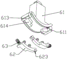
The lower end of the extension shell 1 is provided with membrane separation assemblies 6 which are respectively used for separating the clamping frames 4 at two ends of the clamping frames 4 in the rotating direction; the membrane splitting assembly 6 comprises a membrane splitting press block 61 longitudinally connected to the lower end of the extension shell 1 in a sliding manner and two symmetrically arranged membrane splitting pull bars 62 connected to the lower end of the membrane splitting press block 61 in a sliding manner along the rotation direction of the clamping frame 4; the extension shell 1 is internally provided with a driving sleeve 7 which is longitudinally connected with the periphery of the main driving rod 3 in a sliding manner and is used for driving each film separation pressing block 61 to longitudinally slide.
Second through holes 113 which are longitudinally and slidably connected with the corresponding film separation pressing blocks 61 are symmetrically formed at the lower end of the mounting rack 11 and positioned outside the rotating hole 111; a plurality of first fixing holes 612 which are uniformly arranged are formed in the central position of the upper end of each film-separating pressing block 61; two extension rods 73 respectively fixedly connected with the corresponding film-separating pressing blocks 61 are symmetrically formed at the lower end of the driving sleeve 7; a plurality of second fixing holes 731 which are coaxially arranged with the corresponding first fixing holes 612 are respectively formed on one side of each extension rod 73 facing the corresponding film-dividing press block 61; the first fixing hole 612 and the second fixing hole 731 are fixedly connected by a pin.
A button 72 for driving the driving sleeve 7 to slide longitudinally is formed at the upper end of the driving sleeve 7 above the main driving rod 3; a button sliding hole 122 which penetrates through the extension shell 1 and is used for enabling the button 72 to penetrate out of the outer side of the extension shell 1 is formed at the upper end of the extension shell 1; a second spring 71 for sliding the driving sleeve 7 upward is provided between the driving sleeve 7 and the extension case 1; a lower spring pressing plate 14 which is abutted against the second spring 71 is formed in the extension shell 1; naturally, the second spring 71 causes the driving sleeve 7 to be in an upper limit position.
Membrane separation raised heads 42 are respectively formed at the upper end of the clamping frame 4 close to each membrane separation component 6; the lower end of the film-separating brace 62 is respectively formed with film-separating convex blocks 622 which can be abutted against the corresponding film-separating raised heads 42; a driving raised head 2011 capable of driving the corresponding film separation brace 62 to slide is formed at the upper end of the bucket; a driven groove 623 capable of being inserted into the driving nose 2011 is formed in one side, away from the corresponding tension spring 63, of the film separation pull strip 62; the lower end of each film separating press block 61 is respectively formed with a limiting block 614 which can be abutted against the corresponding film separating raised head 42.
The lower end of each film-dividing press block 61 is symmetrically formed with a sliding arc groove 611 connected with the corresponding film-dividing press block 62 in a sliding manner; the upper end of each film-dividing brace 62 is fixedly connected with a sliding head 621 which is slidably connected with the corresponding sliding arc groove 611; a tension spring 63 for keeping the film-separating pull-strip 62 at one side limit position is respectively arranged between each film-separating pull-strip 62 and the corresponding film-separating press block 61; in a natural state, the lower ends of the two buckets abut against each other, each film separating brace 62 is located at a corresponding limit position on one side, and the film separating press block 61 moves downwards to enable each film separating lug 622 to abut against the corresponding film separating raised head 42.
When the driving sleeve 7 is located at the upper limit position, the film separating protruding head 42 is not in contact with the film separating protruding block 622, the driving protruding head 2011 is located outside the driven groove 623, and the clamping frame 4 can enable the film to coat garbage.
When the driving sleeve 7 is located at the lower limit position, the film separating protruding head 42 abuts against the film separating protruding block 622, the driving protruding head 2011 is located at the inner side of the driven groove 623, the bucket rotates outwards, so that the driving protruding head 2011 drives the driven groove 623 to move, the film separating pull strip 62 moves, the film separating protruding block 622 drives the film separating protruding head 42 to move until the film separating protruding head 42 abuts against the limiting block 614, and therefore the clamping frame 4 is uniformly and equidistantly separated from the two buckets, and garbage falls. The direct contact of hands is not needed, the operation is convenient, and the device is clean and sanitary.
A film inlet groove 204b for inserting a film is formed at the lower end of the second bucket 20b close to the first bucket 20a along the rotating shaft direction of the second bucket 20 b; a film clamping rod 51 which can be tightly abutted against the inner wall of the film entering groove 204b is connected in the film entering groove 204b in a sliding manner along the width direction; the lower end of the film clamping rod 51 is formed with a lower convex strip 512 which is connected in the film inlet groove 204b in a sliding manner along the width direction of the film inlet groove 204 b; a driving frame 52 for driving the film clamping rod 51 to slide is slidably connected in the second bucket 20 b.
Third springs 53 for tightly abutting the lower protruding strips 512 against the inner wall of the film inlet groove 204b are respectively arranged between the two ends of the film clamping rod 51 and the second bucket 20 b; spring retainers 207 that abut against the corresponding third springs 53 are formed in the second bucket 20 b; sliding grooves 205 slidably connected to both ends of the driving frame 52 in the sliding direction are formed in the inner wall of the second bucket 20 b.
Driven inclined planes 511 which extend upwards and are obliquely arranged are formed at the two ends of the film clamping rod 51 respectively; the lower end of the driving frame 52 is respectively formed with a driving inclined plane 521 which can be abutted against the corresponding driven inclined plane 511; two symmetrically arranged lower pressing columns 54 are fixedly connected to the middle part of the upper end of the driving frame 52 and positioned outside the second bucket 20 b; the upper ends of the second buckets 20b are respectively formed with guide holes 206 which are slidably connected with the corresponding lower compression columns 54; the upper end of each of the lower pressing columns 54 is formed with a cross bar 541 extending towards both sides for facilitating the pressing of the lower pressing column 54.
When the driving frame 52 is located at the lower limit position, the film clamping rod 51 is located at the limit position far away from the first bucket 20a, and a film can be placed between the film clamping rod 51 and the inner wall of the film entering groove 204 b.
When the driving frame 52 is located at the upper limit position, the film clamping rod 51 is located at the limit position close to the first bucket 20a, and the film clamping rod 51 can enable the film to be tightly abutted against the inner wall of the film entering groove 204b, so that the film and the second bucket 20b can be relatively fixed.
Before picking up garbage, a film needs to be fixed, the cross bar 541 is pressed down towards the direction of the second bucket 20b, the cross bar 541 moves to enable the lower pressing column 54 to drive the driving frame 52 to move towards the film clamping rod 51, the driving inclined plane 521 abuts against the driven inclined plane 511 and drives the driven inclined plane 511 to move, further the film clamping rod 51 moves towards the direction away from the first bucket 20a to the limit position, meanwhile, the third spring 53 is compressed, and at the moment, the film can be placed between the film clamping rod 51 and the inner wall of the film entering groove 204 b; the tail end of the film is inserted into the film inserting groove 204b, the cross rod 541 is loosened, the film clamping rod 51 moves to the limit position towards the first bucket 20a under the action of the elastic force of the third spring 53, the lower protruding strip 512 and the inner wall of the film inserting groove 204b clamp the film, so that the film and the second bucket 20b are relatively fixed, the film replacing operation is simple, and labor and force are saved.
A release arc surface 522 is formed at the upper end of one side of the driving frame 52 facing the film-separating pressing block 61; a film release plate 613 which can abut against the release arc surface 522 is formed on the side of each of the film separating compacts 61 facing the second bucket 20 b.
When the driving sleeve 7 is located at the upper limit position, the film releasing plate 613 is not in contact with the releasing arc 522, and the film is fixed relative to the second bucket 20b, so that the garbage can be picked up.
When the driving sleeve 7 is located at the lower limit position, the outward rotation of the bucket will make the film release plate 613 abut against the release arc surface 522, so that the driving frame 52 moves to the lower limit position, the film is separated from the film inlet groove 204b, and when garbage is discarded, the tail end of the film does not need to be released, so that the tail end of the film can be separated from the second bucket 20b without adding a new operation step.
When the picked garbage is discarded, the film close to the film shaft 21 is cut off, the button 72 is pressed to enable the driving sleeve 7 to move towards the bucket, the driving sleeve 7 enables the extension rod 73 to drive the film separating pressure block 61 to move towards the bucket, the driving protrusions 2011 enter the driven grooves 623, meanwhile, each film separating protrusion 42 abuts against the corresponding film separating convex block 622, then the main driving rod 3 drives the two buckets to rotate outwards to the limit positions, the driving protrusions 2011 drives the driven grooves 623 to move, then the film separating pull bars 62 move outwards until the film separating protrusions 42 move to abut against the limit blocks 614, and each clamping frame 4 is equidistantly separated and separated from the bucket. Meanwhile, the outward movement of the second bucket 20b causes the release arc 522 to abut against the film release plate 613 and drive the driving rack 52 to move toward the film clamping rod 51, the lower protrusion 512 no longer abuts against the inner wall of the film insertion groove 204b, and the film end is separated from the second bucket 20 b. The film of rubbish and parcel rubbish will drop under the action of gravity, and then with the scraper bowl separation, the abandonment process need not the direct contact of hand, and easy operation is convenient, clean health.
Two linkage columns 341 respectively connected with the corresponding buckets are symmetrically formed at the lower end of the main driving rod 3; a holding frame 12 which horizontally extends towards the outer side and is used for holding the extension shell 1 is formed at the upper end of the extension shell 1; the upper end of the main driving rod 3 is positioned in the holding frame 12, and a handle 31 which horizontally extends outwards and is used for driving the main driving rod 3 to longitudinally slide is formed.
A first spring 32 for moving the main driving rod 3 to the lower end is arranged between the main driving rod 3 and the extension shell 1; an upper spring pressing plate 13 which is abutted against the first spring 32 is formed in the extension shell 1; a spring limiting plate 33 which is abutted against the lower end of the first spring 32 is formed on the outer wall of the main driving rod 3 below the upper spring pressing plate 13; in a natural state, the first spring 32 enables the main driving rod 3 to be located at a lower limit position, and the lower ends of the two buckets are abutted; the hand portion grips the portion of gripping 12, the finger can with handle 31 offsets, holds the hand portion tightly, and the finger can drive handle 31 rebound, and then makes two the scraper bowl rotates to both sides, makes the scraper bowl lower extreme no longer offsets, and then can pick up rubbish, and easy operation is convenient.
The upper part of the outer side of the first bucket 20a far away from the second bucket 20b is formed with a film bin 208 for accommodating the film shaft 21; the outer side of the film bin 208 is detachably connected with a cover 22 for closing the film bin 208.
The inner walls of the film bin 208 at two ends of the rotating shaft of the first bucket 20a are respectively formed with a rotating shaft rotating groove 2081 with an external opening; a rotating shaft 211 which is coaxially arranged with the rotating shaft of the film shaft 21 and can be rotatably connected with the rotating shaft rotating groove 2081 is respectively formed at the two ends of the film shaft 21; a film placing groove 2082 which is communicated with the first bucket 20a and is used for enabling a film to penetrate into the first bucket 20a is formed at the lower end of the film bin 208 along the direction of the rotating shaft of the first bucket 20 a; the lower end of the inner wall of the first bucket 20a is formed with a film outlet groove 204a which is communicated with the outside along the direction of the rotating shaft of the first bucket 20a and is used for enabling the film to pass through the first bucket 20 a.
When the film shaft 21 is installed, the cover 22 is removed, the film of the film shaft 21 is inserted into the first bucket 20a from the film bin 208 through the film placing groove 2082, then both ends of the rotating shaft 211 are respectively placed into the bottom of the rotating shaft rotating groove 2081, then the cover 22 is covered again, the film is pulled out to the outside, so that the film passes through the film outlet groove 204a, and then the film is fixedly connected to the second bucket 20 b.
In an initial state, the lower protrusion strips 512 abut against the inner wall of the film inlet groove 204b, and the engaging plates 209 engage with the respective holding frames 4, so that the respective holding frames 4 are fixed relative to the first bucket 20 a.
Before using the product, a film for wrapping garbage needs to be installed, the extending shell 1 is held by hands, the sealing cover 22 is removed, the film of the film shaft 21 is unfolded outwards, and the film penetrates into the first bucket 20a from the film bin 208 through the film placing groove 2082. Then, the two ends of the rotating shaft 211 are respectively placed into the rotating shaft rotating groove 2081, the film shaft 21 is pressed inwards to enable the rotating shaft 211 to move to the bottom of the rotating shaft rotating groove 2081, the film shaft 21 can rotate in the rotating shaft rotating groove 2081, a film is used, and then the sealing cover 22 is covered again. The holding frame 12 is held to hand portion, and the finger offsets with handle 31, holds hand portion tightly, and the finger drives handle 31 to keeping away from the motion of scraper bowl direction, and handle 31 motion makes the motion of main actuating lever 3, and first spring 32 compresses simultaneously. The main driving rod 3 moves to enable the auxiliary driving rod 34 to move in the direction away from the bucket, the auxiliary driving rod 34 moves to enable the linkage column 341 to drive the linkage groove 203 to move, then the two buckets rotate outwards around the linkage pipe 202, and the lower ends of the two buckets are not abutted. The film is pulled outwards, so that the film passes through the first bucket 20a outwards through the film outlet groove 204a, the handle 31 is loosened, the main driving rod 3 moves to the original position under the action of the elastic force of the first spring 32, and meanwhile, the two buckets are driven by the linkage column 341 to rotate inwards, so that the lower ends of the two buckets are abutted.
When the product is used, the cross bar 541 is pressed towards the second bucket 20b and the position of the cross bar 541 is kept relatively fixed, the cross bar 541 moves to enable the lower pressing column 54 to drive the driving frame 52 to move towards the film clamping rod 51, the driving frame 52 moves to enable the driving inclined plane 521 to abut against the driven inclined plane 511 and drive the driven inclined plane 511 to move, and then the film clamping rod 51 moves towards the direction far away from the first bucket 20a, and meanwhile, the third spring 53 compresses. Then, the film positioned outside the first bucket 20a is pulled, the end of the film is inserted into the film-inserting groove 204b, the cross bar 541 is released, the film-clamping rod 51 moves towards the first bucket 20a under the action of the elastic force of the third spring 53, and the lower protruding strip 512 and the inner wall of the film-inserting groove 204b clamp the film, so that the film and the second bucket 20b are relatively fixed. At the same time, the movement of the film clamping rod 51 also causes the driven inclined surface 511 to drive the driving inclined surface 521, so that the driving frame 52 moves away from the second bucket 20b to approach the original position.
When picking up rubbish, the holding frame 12 is held to hand, and the finger offsets with handle 31, grips hand, and the finger will make handle 31 to keeping away from the motion of scraper bowl direction, and first spring 32 compresses simultaneously, and then makes main actuating lever 3 drive two scraper bowls and rotate to the outside, and the scraper bowl lower extreme no longer offsets. The lower extreme of second scraper bowl 20b and first scraper bowl 20a keeps away from each other for the film is pulled out, offsets film middle part and rubbish upper end, and the hand loosens gradually simultaneously, and two scraper bowl lower extremes are close to each other, and the film middle part is upwards arched. When two scraper bowl lower extremes offset once more, the film has totally wrapped up rubbish, the wall of the simultaneously shovel bucket makes rubbish break away from with ground, the film is located between holding frame 4 and the fixed plate 201, two scraper bowl lower extremes offset and make holding frame 4 and fixed plate 201 press from both sides tight film, the thickness of film makes first grafting portion 2012 and second grafting portion 44 can interference fit, first grafting portion 2012 is pegged graft with second grafting portion 44, and then make the wrapped rubbish of film keep apart completely with the external world, there is not the peculiar smell, and pick up the process and need not the hand contact, clean health.
When picking up the rubbish again, the hands are gripped again, so that the two buckets rotate outwards, and the first inserting part 2012 is inserted into the second inserting part 44. When the two buckets rotate outward again, the first inserting portion 2012 is inserted into the second inserting portion 44 so that the holding frame 4 adjacent to the second bucket 20b is separated from the clamping plate 209. The pulled film is located between two adjacent clamping frames 4 close to the second bucket 20b, when the film is picked up again, the two adjacent clamping frames 4 enable the film located between the two adjacent clamping frames 4 to cover garbage, meanwhile, the film enables the second inserting parts 44 of the two adjacent clamping frames 4 to be in interference fit, the two second inserting parts 44 are inserted into each other, and the two clamping frames 4 and the second bucket 20b are fixed relatively. The garbage can be picked up for multiple times, and the picked garbage is stored in the film in a mutually separated mode. In particular, when the last holding frame 4 finishes picking up the garbage, the garbage can not be picked up again, and the hands can not be held so that the two buckets rotate outwards, thereby preventing the finally picked-up garbage from falling.
When the picked-up garbage is discarded, the holding frame 12 is held by hand, fingers abut against the handle 31, the film is cut along the film outlet groove 204a, and the bucket is moved to a position above the garbage can or a designated discarding position. When the button 72 is pressed, the driving sleeve 7 moves towards the bucket direction, and the second spring 71 is compressed, so that the movement of the driving sleeve 7 enables the extension rod 73 to drive the film separating press block 61 to move towards the bucket direction, and further the driving raised heads 2011 enter the driven grooves 623, and meanwhile, each film separating raised head 42 abuts against the corresponding film separating convex block 622. Then, the hands are gripped, so that the main driving rod 3 drives the two buckets to rotate outwards to the extreme positions, meanwhile, the first spring 32 is compressed, the buckets rotate, so that the driving protruding head 2011 drives the driven groove 623 to move, and then the film scoring pull strip 62 moves outwards. The film separating pull strip 62 moves outwards to enable the film separating convex block 622 to drive the film separating convex head 42 to move until the film separating convex head 42 is tightly abutted against the limiting block 614, and all the clamping frames 4 are separated at equal intervals and separated from the bucket. Meanwhile, the outward movement of the second bucket 20b causes the release arc 522 of the driving frame 52 to abut against the film release plate 613, and along with the rotation of the second bucket 20b, the driving frame 52 moves towards the film clamping rod 51, and further drives the film clamping rod 51 to move towards the direction away from the first bucket 20a, the lower protrusion 512 no longer abuts against the inner wall of the film inlet groove 204b, and the tail end of the film is separated from the second bucket 20 b. The film of rubbish and parcel rubbish will drop under the action of gravity, and then with the scraper bowl separation, the process of abandoning need not the direct contact of hand, easy operation is convenient, clean health.
After discarding the completion, loosen handle 31, main drive pole 3 moves to the home position under the spring action of first spring 32, and two buckets rotate to the lower extreme inboard simultaneously and offset, and two buckets drive respectively simultaneously and divide membrane brace 62 to move to the home position. The inward movement of the bucket also causes the fixing plates 201 on the two buckets to clamp each clamping frame 4, so that each clamping hole 43 is clamped with the corresponding clamping head 2091, and the clamping plate 209 causes each clamping frame 4 to be relatively fixed with the first bucket 20 a. Meanwhile, the film releasing plate 613 is no longer in contact with the driving rack 52, the film clamping rod 51 moves to the far position under the elastic force of the third spring 53, and the lower protruding strip 512 abuts against the inner wall of the film entering groove 204 b. Subsequently, the button 72 is released, the driving sleeve 7 moves to the original position under the action of the elastic force of the second spring 71, the driving sleeve 7 moves to drive the film separating press block 61 to move to the original position, the driven groove 623 is separated from the driving raised head 2011, meanwhile, the film separating convex block 622 does not abut against the film separating raised head 42 any more, and then the product is stored.
According to the invention, the buckets are arranged, the holding frame 12 is held by hands, fingers can be conveniently contacted with the handles 31, the lower ends of the two buckets are mutually far away by lifting the handles 31, so that the garbage can be conveniently picked up, the operation is simple and convenient, the hands are not directly contacted with the garbage, the garbage can be cleaned and cleaned, the time and the labor are saved, meanwhile, the film is arranged in the first bucket 20a, the tail end of the film is fixedly connected with the second bucket 20b, when the garbage is picked up, the garbage is wrapped in the film, so that the peculiar smell of the garbage cannot be volatilized outwards, meanwhile, the buckets are prevented from being stained, and the convenience and the sanitation are realized.
According to the garbage collecting device, the clamping frames 4 are arranged, when garbage is not collected, the clamping frames 4 and the clamping plate 209 are fixed relatively, so that the clamping frames 4 and the first bucket 20a are fixed relatively, when garbage is collected, the films can be clamped between the clamping frames 4 and the fixing plate 201, the garbage located in the middle of the films is wrapped and isolated from the outside, no peculiar smell exists, the garbage collecting device is clean and sanitary, meanwhile, the thickness of the films enables the first inserting portion 2012 and the second inserting portion 44 of the adjacent clamping frame 4 to be inserted and connected, and the clamping frames 4 and the clamping plate 209 can be separated due to the inserting strength, so that the garbage can be collected for multiple times, the garbage collected each time can be separated from each other, the garbage collecting device is simple and convenient to operate, and can meet the requirement of multiple times of use, and is clean and sanitary.
According to the garbage disposal device, the film separating assembly 6 is arranged, when the button 72 is pressed down to discard garbage, the bucket rotates outwards to drive the film separating pull strips 62 to move towards two sides respectively, the film separating convex blocks 622 drive the film separating convex heads 42 to move to abut against the limiting blocks 614, so that the clamping frames 4 are equidistantly separated and separated from the two buckets, and the picked garbage can automatically fall down; meanwhile, the second bucket 20b rotates outwards to enable the film release plate 613 to abut against the release arc surface 522 and drive the release arc surface 522 to move, so that the driving frame 52 moves towards the film clamping rod 51, the film clamping rod 51 does not clamp the tail end of the film, the film is separated from the second bucket 20b, no new operation step is added, the film between the two buckets and the garbage wrapped by the film can be separated from the buckets, a hand is not needed to directly contact the film, and the film peeling machine is simple to operate and clean and sanitary.
The garbage can be conveniently picked up without hand contact, and the operation is simple and convenient; the film can wrap the garbage, so that the garbage is isolated from the outside, peculiar smell is prevented from diffusing, and the film is clean and sanitary; the garbage collecting device can collect a plurality of garbage, and the collected garbage can not be separated because the garbage is relatively independent to be collected each time; the garbage can be conveniently discarded, a hand does not need to contact the film, the operation is simple and convenient, and the garbage can is clean and sanitary and provides convenience for life.
Claims (10)
1. A garbage picking mechanism comprises an extension shell and two buckets which are symmetrically and rotatably connected to a rotating shaft at the lower end of the extension shell and are horizontally arranged; the method is characterized in that: the two buckets are respectively a first bucket and a second bucket; a film shaft wound with a film for wrapping garbage is rotatably connected to the outer side of the first bucket; the end of the film wound on the film shaft can be fixedly connected with the second bucket.
2. A waste picking mechanism as claimed in claim 1, in which: a main driving rod for driving the two buckets to rotate is longitudinally and slidably connected in the extension shell; the buckets open and close to move the film between the two buckets.
3. A waste picking mechanism as claimed in claim 2, in which: the lower end of the extension shell is positioned between the two buckets and is rotatably connected with a plurality of clamping frames with rotating shafts horizontally arranged; second inserting parts which can be inserted into each other are formed on two sides, facing the bucket, of each clamping frame respectively; a clamping plate capable of blocking the movement of each clamping frame is formed on the inner side of the first bucket; a first inserting part capable of being inserted into the second inserting part is formed on one side, facing the clamping frame, of each bucket; when the two ends of the clamping frame are not provided with films, the clamping plate enables the clamping frame and the first bucket to be relatively fixed; when a film is arranged at any end of the clamping frame, the second insertion part or the first insertion part positioned on one side of the film is inserted into the clamping frame, so that the clamping frame and the second bucket are relatively fixed.
4. A waste picking mechanism as claimed in claim 3, in which: the lower end of the extension shell is positioned at two ends of the clamping frame in the rotating direction and is respectively provided with a membrane splitting assembly used for separating each clamping frame; the membrane splitting assembly comprises a membrane splitting press block longitudinally connected to the lower end of the extension shell in a sliding mode and a membrane splitting brace slidably connected to the lower end of the membrane splitting press block along the rotation direction of the clamping frame.
5. A waste picking mechanism as claimed in claim 4, in which: a driving sleeve for driving each membrane separation pressing block to longitudinally slide is longitudinally connected to the periphery of the main driving rod in the extension shell in a sliding manner; membrane separation raised heads are respectively formed at the upper end of the clamping frame close to each membrane separation component; and film separating convex blocks which can be abutted against the corresponding film separating convex heads are respectively formed at the lower ends of the film separating pull strips.
6. A waste picking mechanism as claimed in claim 5, in which: a driving convex head capable of driving the corresponding film separation brace to slide is formed at the upper end of the bucket; when the driving sleeve is located at the upper limit position, the film separating raised heads are not in contact with the film separating lugs, and the film can be wrapped by the clamping frame;
when the driving sleeve is located at the lower limit position, the film separating protruding head abuts against the film separating protruding block, the scraper bucket rotates outwards to enable the film separating protruding block to drive the film separating protruding head to move, the clamping frame is further separated, and garbage falls.
7. A waste picking mechanism as claimed in claim 5, in which: a film inlet groove for penetrating a film is formed at the lower end of the second bucket; a film clamping rod capable of tightly abutting against the inner wall of the film entering groove is connected in the film entering groove in a sliding mode along the width direction; a driving frame used for driving the film clamping rod to slide is connected in the second bucket in a sliding mode;
when the driving frame is located at the lower limit position, the film clamping rod is located at the limit position far away from the first bucket, and a film can be placed between the film clamping rod and the inner wall of the film inserting groove; when the driving frame is located at the upper limit position, the film clamping rod is located at the limit position close to the first bucket, the film clamping rod can enable the film to be tightly abutted to the inner wall of the film entering groove, and then the film and the second bucket can be relatively fixed.
8. A waste picking mechanism as claimed in claim 7, in which: a release arc surface is formed at the upper end of one side of the driving frame, which faces the film separation pressing block; a film release plate capable of abutting against the release arc surface is formed on one side, facing the second bucket, of each film separation pressing block;
when the driving sleeve is positioned at the upper limit position, the film release plate is not contacted with the release arc surface; when the driving sleeve is located at the lower limit position, the bucket rotates outwards to enable the film release plate to be abutted against the release arc surface, and then the driving frame moves to the lower limit position.
9. A waste picking mechanism as claimed in claim 5, in which: the lower end of the main driving rod is symmetrically formed with two linkage columns which are respectively connected with the corresponding buckets; a holding frame which horizontally extends towards the outer side and is used for holding the extension shell is formed at the upper end of the extension shell; the upper end of the main driving rod is positioned in the holding frame, and a handle which horizontally extends outwards and is used for driving the main driving rod to longitudinally slide is formed in the holding frame.
10. A waste picking mechanism as claimed in claim 1, in which: a film bin for accommodating the film shaft is formed outside the first bucket; the outer side of the film bin is detachably connected with a sealing cover used for sealing the film bin.
Applications Claiming Priority (2)
| Application Number | Priority Date | Filing Date | Title |
|---|---|---|---|
| CN202110048625 | 2021-01-14 | ||
| CN2021100486255 | 2021-01-14 |
Publications (1)
| Publication Number | Publication Date |
|---|---|
| CN114032829A true CN114032829A (en) | 2022-02-11 |
Family
ID=80140642
Family Applications (1)
| Application Number | Title | Priority Date | Filing Date |
|---|---|---|---|
| CN202111522658.5A Pending CN114032829A (en) | 2021-01-14 | 2021-12-14 | Garbage picking mechanism |
Country Status (1)
| Country | Link |
|---|---|
| CN (1) | CN114032829A (en) |
Citations (9)
| Publication number | Priority date | Publication date | Assignee | Title |
|---|---|---|---|---|
| EP0361117A2 (en) * | 1988-09-01 | 1990-04-04 | Friedrich Fuhrmann | Waste pick-up device, especially for dog excrements |
| ES1045257U (en) * | 1999-12-13 | 2000-08-16 | Segui Magdalena Gual | A device for collecting animal feces. (Machine-translation by Google Translate, not legally binding) |
| US20080265592A1 (en) * | 2007-04-25 | 2008-10-30 | Four Paws Products, Ltd. | Animal waste collection device with integrated bag dispenser |
| US20100096867A1 (en) * | 2008-10-21 | 2010-04-22 | Flinn Douglas G | Pickup device for animal waste |
| US20150001332A1 (en) * | 2013-06-29 | 2015-01-01 | Jimmy Qin | Pet Waste Bag Kit |
| CN207700125U (en) * | 2017-12-12 | 2018-08-07 | 深圳市兴日生实业有限公司 | Pet excrement pickup device |
| CN108547246A (en) * | 2018-06-19 | 2018-09-18 | 朱正直 | A kind of animal excrements pick up dung device |
| CN208995970U (en) * | 2018-09-27 | 2019-06-18 | 昆山好创电子科技有限公司 | A kind of portable pet dejection collecting equipment |
| CN209040055U (en) * | 2015-12-09 | 2019-06-28 | 摩西虎有限责任公司 | Dog faecal collecting device and its deserted bag body |
-
2021
- 2021-12-14 CN CN202111522658.5A patent/CN114032829A/en active Pending
Patent Citations (9)
| Publication number | Priority date | Publication date | Assignee | Title |
|---|---|---|---|---|
| EP0361117A2 (en) * | 1988-09-01 | 1990-04-04 | Friedrich Fuhrmann | Waste pick-up device, especially for dog excrements |
| ES1045257U (en) * | 1999-12-13 | 2000-08-16 | Segui Magdalena Gual | A device for collecting animal feces. (Machine-translation by Google Translate, not legally binding) |
| US20080265592A1 (en) * | 2007-04-25 | 2008-10-30 | Four Paws Products, Ltd. | Animal waste collection device with integrated bag dispenser |
| US20100096867A1 (en) * | 2008-10-21 | 2010-04-22 | Flinn Douglas G | Pickup device for animal waste |
| US20150001332A1 (en) * | 2013-06-29 | 2015-01-01 | Jimmy Qin | Pet Waste Bag Kit |
| CN209040055U (en) * | 2015-12-09 | 2019-06-28 | 摩西虎有限责任公司 | Dog faecal collecting device and its deserted bag body |
| CN207700125U (en) * | 2017-12-12 | 2018-08-07 | 深圳市兴日生实业有限公司 | Pet excrement pickup device |
| CN108547246A (en) * | 2018-06-19 | 2018-09-18 | 朱正直 | A kind of animal excrements pick up dung device |
| CN208995970U (en) * | 2018-09-27 | 2019-06-18 | 昆山好创电子科技有限公司 | A kind of portable pet dejection collecting equipment |
Similar Documents
| Publication | Publication Date | Title |
|---|---|---|
| KR100788777B1 (en) | Dust collector and electric vacuum cleaner | |
| TWM552334U (en) | Separating apparatus and vacuum cleaner | |
| CN111389490B (en) | Buddha linden peeling apparatus | |
| CN111283824B (en) | A slotting device for processing wooden spoons | |
| CN220588179U (en) | One-key cleaning type dust cup of dust collector | |
| CN109819764B (en) | Corn leaf removing device | |
| CN213148342U (en) | Construction engineering supervision sampler convenient to carry | |
| CN114894552A (en) | Water environment detects with layer-stepping water sampling device | |
| CN218813441U (en) | A new type of sanitation garbage clip | |
| CN101612023A (en) | Dust collecting device and electric vacuum cleaner using the same | |
| CN215349962U (en) | Box-packed visual ear picking tool | |
| CN215227328U (en) | Dustpan | |
| CN117071487B (en) | Pet excrement picking device | |
| CN216878353U (en) | Portable waste incineration flue gas detection device | |
| CN214853669U (en) | Rock wall honey is picked and is picked with honey stripping and slicing grabber | |
| CN210146444U (en) | Waste concrete separation equipment | |
| CN113471886A (en) | Peeling mechanism in middle of high efficiency | |
| CN113712386A (en) | Case is deposited to construction drawing based on hydraulic engineering construction | |
| CN114032828A (en) | Handheld pet excrement picking device | |
| CN214257208U (en) | Filbert picking device | |
| CN215248583U (en) | Stacking device for gum dipping decorative paper | |
| CN118058647B (en) | Hair removing brush head of household dust collector and hair removing method | |
| CN220767866U (en) | A fallen leaf cleaning device for building landscape | |
| CN219726328U (en) | Cortex dictamni pretreatment cleaning device | |
| CN223979170U (en) | A multi-functional device for blueberry picking |
Legal Events
| Date | Code | Title | Description |
|---|---|---|---|
| PB01 | Publication | ||
| PB01 | Publication | ||
| SE01 | Entry into force of request for substantive examination | ||
| SE01 | Entry into force of request for substantive examination | ||
| WD01 | Invention patent application deemed withdrawn after publication | ||
| WD01 | Invention patent application deemed withdrawn after publication |
Application publication date: 20220211 |