CN114064458A - JTAG debugging method and system with extensible interface and universality - Google Patents
JTAG debugging method and system with extensible interface and universality Download PDFInfo
- Publication number
- CN114064458A CN114064458A CN202111242970.9A CN202111242970A CN114064458A CN 114064458 A CN114064458 A CN 114064458A CN 202111242970 A CN202111242970 A CN 202111242970A CN 114064458 A CN114064458 A CN 114064458A
- Authority
- CN
- China
- Prior art keywords
- jtag
- debugging
- interface
- data
- state
- Prior art date
- Legal status (The legal status is an assumption and is not a legal conclusion. Google has not performed a legal analysis and makes no representation as to the accuracy of the status listed.)
- Granted
Links
Images


Classifications
-
- G—PHYSICS
- G06—COMPUTING OR CALCULATING; COUNTING
- G06F—ELECTRIC DIGITAL DATA PROCESSING
- G06F11/00—Error detection; Error correction; Monitoring
- G06F11/36—Prevention of errors by analysis, debugging or testing of software
- G06F11/362—Debugging of software
- G06F11/3644—Debugging of software by instrumenting at runtime
-
- G—PHYSICS
- G06—COMPUTING OR CALCULATING; COUNTING
- G06F—ELECTRIC DIGITAL DATA PROCESSING
- G06F8/00—Arrangements for software engineering
- G06F8/40—Transformation of program code
- G06F8/41—Compilation
-
- G—PHYSICS
- G06—COMPUTING OR CALCULATING; COUNTING
- G06F—ELECTRIC DIGITAL DATA PROCESSING
- G06F8/00—Arrangements for software engineering
- G06F8/70—Software maintenance or management
- G06F8/71—Version control; Configuration management
-
- G—PHYSICS
- G06—COMPUTING OR CALCULATING; COUNTING
- G06F—ELECTRIC DIGITAL DATA PROCESSING
- G06F8/00—Arrangements for software engineering
- G06F8/70—Software maintenance or management
- G06F8/76—Adapting program code to run in a different environment; Porting
Landscapes
- Engineering & Computer Science (AREA)
- Theoretical Computer Science (AREA)
- General Engineering & Computer Science (AREA)
- Software Systems (AREA)
- Physics & Mathematics (AREA)
- General Physics & Mathematics (AREA)
- Computer Security & Cryptography (AREA)
- Computer Hardware Design (AREA)
- Quality & Reliability (AREA)
- Stored Programmes (AREA)
Abstract
The invention provides a JTAG debugging method and a system with extensible interfaces and universality, which comprises the following steps: the JTAG host controller is packaged into IP equipment of a peripheral bus port; calling hardware resources in the development board, and hanging the JTAG host IP to a hardware system to complete the minimum hardware field programmable gate array design of the debugging system; completing the transplanting work of the boot loader according to the characteristics of the development board; compiling in the transplanted boot loader, and solidifying the binary file to the development board; the debugging device and the upper computer, the debugging device and the target debugging chip, and the upper computer runs the super terminal software and finishes the debugging work of the target chip through a data JTAG debugging instruction. The invention can be flexibly integrated into an embedded system with a processor core, a RAM, a ROM, GPIO pins, JTAG _ MASTER and UART devices, completes the construction of a hardware part of a debugging system and has flexibility; the module JTAG Master controller can realize JTAG protocol conversion and simultaneously connect a plurality of JTAG devices with the same or different characteristics.
Description
Technical Field
The invention relates to the technical field of electronic equipment maintenance, in particular to a Joint Test Action Group (JTAG) debugging method and system with extensible interfaces and universality.
Background
The integrated circuit industry develops according to the law of moore's law, the scale of the integrated circuit is larger and larger, and the circuits which can be integrated on a single chip are more and more complex. Meaning that unknown failure conditions, material defects, and manufacturing variations are more likely to occur during the chip development phase, resulting in situations where the die that is being taped back is not expected to function properly or performance is less than optimal. Thus, based on chip-based design for testability considerations, the IEEE1149.1 standard was published in 1990. At present, in the ARM processor series, the PowerPC processor series and the complex control devices such as PCIE PHY, SATA PHY and EMMC controller in the market, testability hardware logic based on IEEE1149.1 protocol is integrated according to the characteristics of the respective devices, and a JTAG debug interface is provided, so that the online debug function of the devices is supported on hardware.
The debugging system provided by matching each device has strong specificity and high price, and belongs to the development and development of foreign companies. For example, the JTAG debugging system matched with the ARM processor series is a J-Link simulation debugger and matched software provided by SEGGER company of Germany, only an agent is arranged in China at present, and no domestic version exists; the PowerPC processor family is compatible with the RISCmatch emulation debugger and compatible software available from IBM corporation of the United states. TRACE32, later developed by Lauterbach, germany, was able to support the debugging work of the JTAG interface and BDM interface and all CPUs, but the purchase price was more expensive, one TRACE32 purchase price was in the tens of thousands yuan. The debugging equipment is connected with the upper PC through the USB port, matched application software is needed to be used as an interactive interface, the installation of the application software has requirements on an operating system of the upper PC, and the support of a Chinese-made operating system of the kylin class of the winning bid is not good.
The problems to be solved at present are that 1, the purchase price of debugging equipment is too high and is provided by foreign companies, some policies on China at home need to be vigilant at present, and tools related to chip research and development have domestic requirements; 2. the USB ports are used by the debuggers Jlink, trace32 and riscwatch on the market, and the upper computer needs to run matched application software which is not well supported by a domestic operating system; 3. debugging equipment released in the market cannot be connected with a plurality of equipment with different characteristics for debugging, for example, an ARM processor core and a PCIE controller integrated in one chip are jointly debugged with another PCIE chip, the current method is that three TRACE32 debuggers are required to be respectively connected with an ARM processor JTAG interface and main and auxiliary PCIE PHY JTAG interfaces, the TRACE32 software environment limits that an upper computer is required to have three idle USB ports or three upper computers are required to be respectively connected, and the required hardware resources are more; if a TRACE32 switches connections back and forth, it may cause complicated testing operations and the phenomenon cannot be observed simultaneously, which is not favorable for problem location. Therefore, the invention provides a general JTAG debugging system with an extensible interface, which is connected with an upper computer by utilizing a serial port, an interactive interface uses serial port debugging assistants such as a super terminal and the like, does not make requirements on the environment of the upper computer system, is used for solving the problem of localization of the debugging system and the problem of simultaneously connecting a plurality of debugging devices with different characteristics, and realizes the multi-device online debugging function.
Patent document CN113268031A (application number: CN202110631019.6) provides a system and method for a remote debugging tool of electronic equipment, which relates to the technical field of electronic equipment maintenance, wherein the system includes a JTAG service program, an application program running in a Linux operating system, and a function for interacting with a remote program, performing client data transceiving, and providing data transceiving; the hardware board card is used for providing FPGA resources to form an embedded hardware environment, the FPGA resources provided by the hardware board card are used for forming an embedded minimum system, a hardware module necessary for FPGA remote debugging is added to form the hardware board card, the FPGA debugging mode is completed through Ethernet, a service end program is designed in a JTAG data processing program, remote operation of a network communication protocol becomes reality, the FPGA chips are accessed through specified network addresses, the purpose that multiple people jointly access the same chip and debug multiple FPGA chips is achieved, and the use scene of the FPGA debugging mode is wider and more convenient. However, the development of the firmware of the invention depends on the environment which is not a Uboot system, and can not be well operated on various operating systems, so that the compatibility is insufficient.
Patent document CN107290656B (application number: CN201710452885.2) discloses an extensible JTAG debug structure integrating a bidirectional CRC check function, which includes a debug master controller and a debug slave controller; the debugging main controller receives the data of the JTAG interface, performs data verification and instruction analysis, and then transmits the data without error verification to the corresponding debugging sub-controller for further processing and execution, and the debugging sub-controller receives the control of the debugging main controller, and realizes the debugging operation on a debugging object and returns the debugging data according to the corresponding data instruction; the JTAG debugging structure of the invention realizes the bidirectional 32-bit CRC serial data checking function on the basis of supporting the IEEE1149.1 standard JTAG time sequence, can detect the abnormity appearing in the data transmission process and improves the reliability of the data transmission process. However, the invention has no module JTAG Master controller, can not realize JTAG protocol conversion and simultaneously connect JTAG devices with the same or different multipath characteristics, and has insufficient expandability.
The english abbreviations are explained as follows:
JTAG (Joint Test Action Group, Joint Test work Group)
Uboot (Universal Boot Loader, Boot Loader)
JTAG Master (Joint Test Action Group Master, JTAG host)
ROM (Read-Only Memory)
RAM (Random Access Memory)
GPIO (General-Purpose Input/Output, General Purpose Input and Output)
AMBA (Advanced Microcontroller Bus Architecture )
APB (Advanced Peripheral Bus)
TMS (Test Mode Select)
TCK (Test Clock)
TDI (Test Data In, Test Data input)
TDO (Test Data Out)
TRSTn (Test Reset )
TAP (Test Access Port, Test Access interface)
Menu config (menu configuration)
EDA (Electronic design automation)
Zynq-7000(Xil inx a FPGA products, no English abbreviation meaning introduction on official network)
DDR (Double Data Rate SDRAM)
SPI Flash (Serial Peripheral interface Flash)
UART (Universal Asynchronous Receiver/Transmitter )
FPGA (Field Programmable Gate Array)
CMD (Command)
Disclosure of Invention
Aiming at the defects in the prior art, the invention aims to provide a JTAG debugging method and system with extensible interfaces and universality.
The JTAG debugging method of the interface extensible universality provided by the invention comprises the following steps:
step S1: the JTAG host controller is packaged into IP equipment of a peripheral bus port;
step S2: calling hardware resources in the development board, and hanging the JTAG host IP to a hardware system to complete the minimum hardware field programmable gate array design of the debugging system;
step S3: completing the transplanting work of the boot loader according to the characteristics of the development board;
step S4: compiling in the transplanted boot loader, and solidifying the binary file to the development board;
step S5: the debugging device and the upper computer, the debugging device and the target debugging chip, and the upper computer runs the super terminal software and finishes the debugging work of the target chip through a data JTAG debugging instruction.
Preferably, a CPU core, a serial port, a ROM, a RAM, a self-developed JTAG host controller and a universal input and output pin are integrated in the debugging system;
the serial port is connected with the PC interactive port of the upper computer; the ROM is used for storing solidified debugging application software; the RAM is used for storing space required by software operation; the universal input and output pin is used for a JTAG external communication interface; the JTAG host controller is used for realizing protocol conversion operation.
Preferably, in the step S1:
the JTAG host controller converts data into JTAG signals to be output according to an IEEE1149.1 protocol, an AMBA APB interface protocol is selected for JTAG host controller interface design, JTAG interface signals are designed for realizing the online simultaneous connection of a plurality of devices for debugging, and the JTAG interface signals comprise test mode selection, a test clock, test data output, test data input and test reset;
in accordance with the TAP state machine design of the IEEE1149.1 protocol, state transitions are controlled by the TMS, and the JTAG MASTER controller defines 16 states for controlling TMS signal output, including: ST _ TLR logic reset state, ST _ RTI operation idle state, ST _ SDR selection data scanning state, ST _ CDR data capture state, ST _ SHD data shift state, ST _ E1D data exit 1 state, ST _ E2D data exit 2 state, ST _ PDR data transmission pause state, ST _ UDR update data value state, ST _ SIR selection instruction scanning state, ST _ CIR instruction capture state, ST _ SHI instruction shift state, ST _ E1I instruction exit 1 state, ST _ PIR instruction transmission pause state, ST _ E2I instruction exit 2 state, ST _ UIR update instruction value state, and the effect of transferring a register configuration instruction into a JTAG protocol to be transmitted to a target mode adjusting device is realized;
the JTAG host provides registers for corresponding functions for the JTAG interface.
Preferably, in the step S3:
the firmware development matched with hardware is developed based on a Uboot environment, UBoot is a bootstrap program before the start of an embedded operating system, codes are open, and various types of embedded processors can be supported.
Preferably, in the step S4:
according to the file format, adding command configuration option information of a JTAG host, respectively defining a group of debugging instructions aiming at JTAG interfaces, selecting whether debugging system firmware is added into a UBoot compiling environment by the JTAG host configuration option, compiling to generate a bin file after successful selection, and solidifying the content to a debugging device through an electronic design automation tool.
The invention provides a JTAG debugging system with extensible interfaces and universality, which comprises:
module M1: the JTAG host controller is packaged into IP equipment of a peripheral bus port;
module M2: calling hardware resources in the development board, and hanging the JTAG host IP to a hardware system to complete the minimum hardware field programmable gate array design of the debugging system;
module M3: completing the transplanting work of the boot loader according to the characteristics of the development board;
module M4: compiling in the transplanted boot loader, and solidifying the binary file to the development board;
module M5: the debugging device and the upper computer, the debugging device and the target debugging chip, and the upper computer runs the super terminal software and finishes the debugging work of the target chip through a data JTAG debugging instruction.
Preferably, a CPU core, a serial port, a ROM, a RAM, a self-developed JTAG host controller and a universal input and output pin are integrated in the debugging system;
the serial port is connected with the PC interactive port of the upper computer; the ROM is used for storing solidified debugging application software; the RAM is used for storing space required by software operation; the universal input and output pin is used for a JTAG external communication interface; the JTAG host controller is used for realizing protocol conversion operation.
Preferably, in said module M1:
the JTAG host controller converts data into JTAG signals to be output according to an IEEE1149.1 protocol, an AMBA APB interface protocol is selected for JTAG host controller interface design, JTAG interface signals are designed for realizing the online simultaneous connection of a plurality of devices for debugging, and the JTAG interface signals comprise test mode selection, a test clock, test data output, test data input and test reset;
in accordance with the TAP state machine design of the IEEE1149.1 protocol, state transitions are controlled by the TMS, and the JTAG MASTER controller defines 16 states for controlling TMS signal output, including: ST _ TLR logic reset state, ST _ RTI operation idle state, ST _ SDR selection data scanning state, ST _ CDR data capture state, ST _ SHD data shift state, ST _ E1D data exit 1 state, ST _ E2D data exit 2 state, ST _ PDR data transmission pause state, ST _ UDR update data value state, ST _ SIR selection instruction scanning state, ST _ CIR instruction capture state, ST _ SHI instruction shift state, ST _ E1I instruction exit 1 state, ST _ PIR instruction transmission pause state, ST _ E2I instruction exit 2 state, ST _ UIR update instruction value state, and the effect of transferring a register configuration instruction into a JTAG protocol to be transmitted to a target mode adjusting device is realized;
the JTAG host provides registers for corresponding functions for the JTAG interface.
Preferably, in said module M3:
the firmware development matched with hardware is developed based on a Uboot environment, UBoot is a bootstrap program before the start of an embedded operating system, codes are open, and various types of embedded processors can be supported.
Preferably, in said module M4:
according to the file format, adding command configuration option information of a JTAG host, respectively defining a group of debugging instructions aiming at JTAG interfaces, selecting whether debugging system firmware is added into a UBoot compiling environment by the JTAG host configuration option, compiling to generate a bin file after successful selection, and solidifying the content to a debugging device through an electronic design automation tool.
Compared with the prior art, the invention has the following beneficial effects:
1. the method can be flexibly integrated into an embedded system with a processor core, a RAM, a ROM, GPIO pins, a JTAG _ MASTER and a UART device, and the building of a hardware part of a debugging system is completed, so that the method has flexibility;
2. the self-research module JTAG Master controller can realize JTAG protocol conversion and simultaneously connect JTAG equipment with the same or different multipath characteristics, realize the online debugging function of multiple devices, customize hardware according to the need for the number of the online debugging hardware, and have expandability;
3. the development of the firmware depends on the environment of a Uboot system, the debugging command is sent only by installing a serial port debugging assistant of a super terminal class on an upper computer as an interactive interface, the performance of a machine configured by the upper computer system is almost not required too much, the system can be operated on various operating systems well, and the compatibility is realized;
UBoot is a bootstrap program before the embedded operating system is started, codes are open, the variety of the embedded processors (PowrPC, ARM, MIPS, x86, XScale and the like) can be supported, the code reliability is high, the stability is good, the UBoot is selected as a firmware development environment of a debugging system, a good hardware support foundation is provided, the type of the selected processor can be supported to cover PowerPC, ARM, x86 and the like when the debugging system is applied to hardware design, and certain universality is achieved.
Drawings
Other features, objects and advantages of the invention will become more apparent upon reading of the detailed description of non-limiting embodiments with reference to the following drawings:
FIG. 1 is a simplified debugging system communication diagram;
FIG. 2 is a hardware block diagram of a debug system;
FIG. 3 is a Jtag _ Master controller state machine;
FIG. 4 is a debugging system set up for zynq-7000;
FIG. 5 is a debug system application interface.
Detailed Description
The present invention will be described in detail with reference to specific examples. The following examples will assist those skilled in the art in further understanding the invention, but are not intended to limit the invention in any way. It should be noted that it would be obvious to those skilled in the art that various changes and modifications can be made without departing from the spirit of the invention. All falling within the scope of the present invention.
Example 1:
the JTAG debugging method of the interface extensible universality provided by the invention comprises the following steps:
step S1: the JTAG host controller is packaged into IP equipment of a peripheral bus port;
step S2: calling hardware resources in the development board, and hanging the JTAG host IP to a hardware system to complete the minimum hardware field programmable gate array design of the debugging system;
step S3: completing the transplanting work of the boot loader according to the characteristics of the development board;
step S4: compiling in the transplanted boot loader, and solidifying the binary file to the development board;
step S5: the debugging device and the upper computer, the debugging device and the target debugging chip, and the upper computer runs the super terminal software and finishes the debugging work of the target chip through a data JTAG debugging instruction.
Specifically, a CPU core, a serial port, a ROM, a RAM, a self-developed JTAG host controller and a universal input and output pin are integrated in the debugging system;
the serial port is connected with the PC interactive port of the upper computer; the ROM is used for storing solidified debugging application software; the RAM is used for storing space required by software operation; the universal input and output pin is used for a JTAG external communication interface; the JTAG host controller is used for realizing protocol conversion operation.
Specifically, in the step S1:
the JTAG host controller converts data into JTAG signals to be output according to an IEEE1149.1 protocol, an AMBA APB interface protocol is selected for JTAG host controller interface design, JTAG interface signals are designed for realizing the online simultaneous connection of a plurality of devices for debugging, and the JTAG interface signals comprise test mode selection, a test clock, test data output, test data input and test reset;
in accordance with the TAP state machine design of the IEEE1149.1 protocol, state transitions are controlled by the TMS, and the JTAG MASTER controller defines 16 states for controlling TMS signal output, including: ST _ TLR logic reset state, ST _ RTI operation idle state, ST _ SDR selection data scanning state, ST _ CDR data capture state, ST _ SHD data shift state, ST _ E1D data exit 1 state, ST _ E2D data exit 2 state, ST _ PDR data transmission pause state, ST _ UDR update data value state, ST _ SIR selection instruction scanning state, ST _ CIR instruction capture state, ST _ SHI instruction shift state, ST _ E1I instruction exit 1 state, ST _ PIR instruction transmission pause state, ST _ E2I instruction exit 2 state, ST _ UIR update instruction value state, and the effect of transferring a register configuration instruction into a JTAG protocol to be transmitted to a target mode adjusting device is realized;
the JTAG host provides registers for corresponding functions for the JTAG interface.
Specifically, in the step S3:
the firmware development matched with hardware is developed based on a Uboot environment, UBoot is a bootstrap program before the start of an embedded operating system, codes are open, and various types of embedded processors can be supported.
Specifically, in the step S4:
according to the file format, adding command configuration option information of a JTAG host, respectively defining a group of debugging instructions aiming at JTAG interfaces, selecting whether debugging system firmware is added into a UBoot compiling environment by the JTAG host configuration option, compiling to generate a bin file after successful selection, and solidifying the content to a debugging device through an electronic design automation tool.
Example 2:
example 2 is a preferred example of example 1, and the present invention will be described in more detail.
Those skilled in the art can understand the JTAG debugging method with an expandable and generic interface provided by the present invention as a specific implementation of a JTAG debugging system with an expandable and generic interface, that is, the JTAG debugging system with an expandable and generic interface can be implemented by executing the step flow of the JTAG debugging method with an expandable and generic interface.
The invention provides a JTAG debugging system with extensible interfaces and universality, which comprises:
module M1: the JTAG host controller is packaged into IP equipment of a peripheral bus port;
module M2: calling hardware resources in the development board, and hanging the JTAG host IP to a hardware system to complete the minimum hardware field programmable gate array design of the debugging system;
module M3: completing the transplanting work of the boot loader according to the characteristics of the development board;
module M4: compiling in the transplanted boot loader, and solidifying the binary file to the development board;
module M5: the debugging device and the upper computer, the debugging device and the target debugging chip, and the upper computer runs the super terminal software and finishes the debugging work of the target chip through a data JTAG debugging instruction.
Specifically, a CPU core, a serial port, a ROM, a RAM, a self-developed JTAG host controller and a universal input and output pin are integrated in the debugging system;
the serial port is connected with the PC interactive port of the upper computer; the ROM is used for storing solidified debugging application software; the RAM is used for storing space required by software operation; the universal input and output pin is used for a JTAG external communication interface; the JTAG host controller is used for realizing protocol conversion operation.
Specifically, in the module M1:
the JTAG host controller converts data into JTAG signals to be output according to an IEEE1149.1 protocol, an AMBA APB interface protocol is selected for JTAG host controller interface design, JTAG interface signals are designed for realizing the online simultaneous connection of a plurality of devices for debugging, and the JTAG interface signals comprise test mode selection, a test clock, test data output, test data input and test reset;
in accordance with the TAP state machine design of the IEEE1149.1 protocol, state transitions are controlled by the TMS, and the JTAG MASTER controller defines 16 states for controlling TMS signal output, including: ST _ TLR logic reset state, ST _ RTI operation idle state, ST _ SDR selection data scanning state, ST _ CDR data capture state, ST _ SHD data shift state, ST _ E1D data exit 1 state, ST _ E2D data exit 2 state, ST _ PDR data transmission pause state, ST _ UDR update data value state, ST _ SIR selection instruction scanning state, ST _ CIR instruction capture state, ST _ SHI instruction shift state, ST _ E1I instruction exit 1 state, ST _ PIR instruction transmission pause state, ST _ E2I instruction exit 2 state, ST _ UIR update instruction value state, and the effect of transferring a register configuration instruction into a JTAG protocol to be transmitted to a target mode adjusting device is realized;
the JTAG host provides registers for corresponding functions for the JTAG interface.
Specifically, in the module M3:
the firmware development matched with hardware is developed based on a Uboot environment, UBoot is a bootstrap program before the start of an embedded operating system, codes are open, and various types of embedded processors can be supported.
Specifically, in the module M4:
according to the file format, adding command configuration option information of a JTAG host, respectively defining a group of debugging instructions aiming at JTAG interfaces, selecting whether debugging system firmware is added into a UBoot compiling environment by the JTAG host configuration option, compiling to generate a bin file after successful selection, and solidifying the content to a debugging device through an electronic design automation tool.
Example 3:
example 3 is a preferred example of example 1, and the present invention will be described in more detail.
The debugging system communication description, as shown in fig. 1, the debugging apparatus is connected to the upper PC via a serial port, and is connected to a debugging target via a JTAG (Joint Test Action Group) interface signal line, the upper PC runs serial port debugging software, such as a super terminal, a serial port debugging assistant, and the like, configures an appropriate baud rate, the debugging apparatus is powered on to start an ubot (Universal Boot Loader), enters a command input window, can select a currently debugged target board (JTAG port number) according to a predefined command, and finally converts into a JTAG interface signal conforming to the characteristics of a target device via a JTAG Master (Joint Test Action Group Master, host), thereby completing the multi-device online debugging Action.
The key points are as follows: flexibility of debugging system
In consideration of manufacturing cost and flexibility of the hardware design of the debugging system, as shown in fig. 2, the minimum hardware structure diagram of the debugging system is that Only a CPU core, a serial port, a ROM (Read-Only Memory), a RAM (Random Access Memory), a self-developed JTAG Master controller, and GPIO (General-Purpose Input/Output) pins need to be integrated inside the debugging system. The serial port supports the common baud rates of 115200bps, 57600bps, 38400bps and the like, and interacts with an upper PC (personal computer); the ROM is used for storing solidified debugging application software; the RAM is used for storing space required by software operation; the GPIO pin is used for a JTAG external communication interface; and the JTAG Master controller is used for realizing protocol conversion operation.
The key points are as follows: JTAG Master controller design-JTAG protocol conversion and multi-channel equipment simultaneous connection are realized
The JTAG Master controller belongs to self-research design, converts Data into JTAG signals and outputs the JTAG signals according to an IEEE1149.1 protocol, and takes the universality into consideration, the interface design of the JTAG Master controller selects an AMBA APB (AMBA, Advanced Microcontroller Bus Architecture) (APB, Advanced Peripheral Bus) interface protocol, and four groups of JTAG interface (TMS, TCK, TDO, TDI, TRSTn) signals, TMS (Test Mode Select), TCK (Test Clock ), TDI (Test Data In, Test Data input), TDO (Test Data Out, Test Data output), TRSTn (Test Reset) are designed for realizing the online simultaneous connection of a plurality of devices for debugging.
In accordance with the TAP (Test Access Port) state machine design of IEEE1149.1 protocol, state transition is controlled by TMS, as shown in fig. 3, JTAG MASTER controller defines 16 states for controlling TMS signal output, including: ST _ TLR (logical reset state), ST _ RTI (operational idle state), ST _ SDR (select data scan state), ST _ CDR (data capture state), ST _ SHD (data shift state), ST _ E1D (data exit 1 state), ST _ E2D (data exit 2 state), ST _ PDR (data transfer pause state), ST _ UDR (update data value state), ST _ SIR (select instruction scan state), ST _ CIR (instruction capture state), ST _ SHI (instruction shift state), ST _ E1I (instruction exit 1 state), ST _ PIR (instruction transfer pause state), ST _ E2I (instruction exit 2 state), ST _ UIR (update instruction value state), enabling the transfer of register configuration instructions to the JTAG protocol to the target debug equipment.
For four JTAG interfaces, the JTAG Master provides four groups of registers for realizing the JTAG of each interface and provides the following register list for supporting the JTAG
The corresponding JTAG Master controller provides registers for the corresponding functions as shown in the table below.

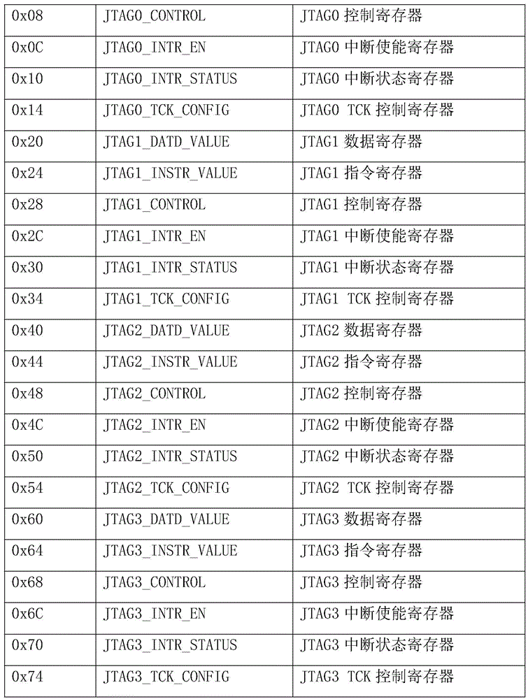
The specific definition of these registers is described below.
(1) JTAGx _ DATD _ VALUE (x ═ 0-3): data register
The specific definition of this register is as follows:

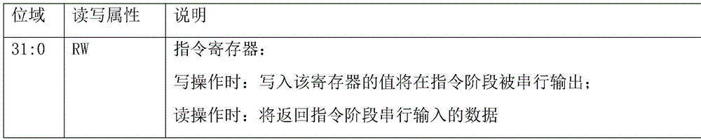
(2) JTAGx _ INSTR _ VALUE (x ═ 0-3): instruction register
The specific definition of this register is as follows:
(3) JTAGx _ CONTROL (x ═ 0-3): control register
The specific definition of this register is as follows:

(4) JTAGx _ INTR _ EN (x ═ 0-3): interrupt status and enable register
The specific definition of this register is as follows:

(5) JTAGx _ INTR _ STATUS (x ═ 0-3): software mode and status register
The specific definition of this register is as follows:
| bit field | Read-write Properties | Description of the invention |
| 31:4 | R | Retention |
| 3 | RW | Interrupt status bit of instruction transfer pause, write 1 clear |
| 2 | RW | Instruction transfer completion interrupt status bit, write 1 clear |
| 1 | RW | Data transfer suspend interrupt status bit, write 1 clear |
| 0 | RW | Interrupt status bit, write 1 clear, data transfer complete |
(6) JTAGx _ TCK _ CONFIG (x ═ 0-3): TCK control register
The specific definition of this register is as follows:

the key points are as follows: the firmware development applies Uboot environment, and the debugging instruction is designed based on the Uboot command system
The firmware development matched with hardware is developed based on a Uboot environment, UBoot is a bootstrap program before the embedded operating system is started, codes are open, the variety of the embedded processors (PowrPC, ARM, MIPS, x86, XScale and the like) can be supported, and the codes are high in reliability and good in stability. The method selects the UBoot as a firmware development environment of the debugging system, has a better hardware support foundation, can support and select the type of the processor to cover PowerPC, ARM, x86 and the like when the hardware of the debugging system is designed and applied, and has certain universality. UBoot is chosen as a development environment, and the existing command system can conveniently complete the development work of JTAG debugging instructions based on C language.
Adding a Command line interface- > JTAG Master configuration option into UBoot source code menucong, increasing the Command configuration option information of JTAG Master according to Uboot cmd/Kconfig file format, realizing that when the menucong configures the graphic interface, the JTAG Master option is selected by selecting a Command line interface option and entering the next level directory, and the JTAG Command is added into the Uboot compiling environment. The part belongs to firmware development content, a group of debugging instructions are respectively defined for four JTAG interfaces, the instruction definition is shown as follows, JTAG Master configuration options select whether to add debugging system firmware into a UBoot compiling environment, after the selection is successful, bin files are compiled and generated, and the content is solidified to a debugging device through an eda (Electronic design automation) tool.
Table debug instruction list


Example 4:
example 4 is a preferred example of example 1, and the present invention will be described in more detail.
A debugging system is built by utilizing Zynq-7000 (a FPGA product of xilinx company, no English abbreviation meaning introduction exists on official website), as shown in FIG. 4, if Zynq-7000 is not used, an FPGA board containing processor core resources, storage resources, configurable GPIO pin resources and UART resources can be used as a substitute, and the processor core can be any one of PowerPC series, ARM series, x86 series and MIPS series corresponding to a firmware development idea. At present, common FPGA boards which can be replaced on the market comprise Zynq-7010\ Zynq-7020\ Zynq UltraScale + MPSoC series with ARM processor core resources, Xilinx Virtex-II Pro series FPGA boards with PowerPC processor core resources and the like.
1. Packaging the self-developed JTAG Master controller into IP equipment of an AMBA APB port by utilizing an eda tool according to the key point 2;
2. calling hardware resources carried in a Zynq-7000 board, an ARM Cortex-a9 CPU core, a DDR (Double Data Rate SDRAM (synchronous dynamic random access memory) controller, DDR storage particles, an SPI Flash (Serial Flash memory) controller, Flash particles, a UART (Universal Asynchronous Receiver/Transmitter) port and GPIO pins, hanging a JTAG _ Master IP to a hardware system through an AMBA APB bus, and completing the design of a minimum hardware FPGA (Field Programmable Gate Array) of a debugging system;
3. completing Uboot transplanting work according to Zynq-7000 plate characteristics;
4. adding the JTAG debugging instruction mentioned in the point 3 into the transplanted Uboot by utilizing a CMD (Command) system, and solidifying the binary file to a Zynq-7000 board after compiling is successful;
5. as shown in fig. 1, the debugging device is connected with the upper computer through a serial port line, the debugging device is connected with the target debugging chip through a JTAG bus, the upper computer runs super terminal software, the super terminal belongs to computer serial interactive terminal software, and can be connected through a serial port, a modem or an ethernet port, and the target chip debugging work is completed through a data JTAG debugging instruction, as shown in fig. 5, a screenshot is taken for a debugging interactive interface.
Those skilled in the art will appreciate that, in addition to implementing the systems, apparatus, and various modules thereof provided by the present invention in purely computer readable program code, the same procedures can be implemented entirely by logically programming method steps such that the systems, apparatus, and various modules thereof are provided in the form of logic gates, switches, application specific integrated circuits, programmable logic controllers, embedded microcontrollers and the like. Therefore, the system, the device and the modules thereof provided by the present invention can be considered as a hardware component, and the modules included in the system, the device and the modules thereof for implementing various programs can also be considered as structures in the hardware component; modules for performing various functions may also be considered to be both software programs for performing the methods and structures within hardware components.
The foregoing description of specific embodiments of the present invention has been presented. It is to be understood that the present invention is not limited to the specific embodiments described above, and that various changes or modifications may be made by one skilled in the art within the scope of the appended claims without departing from the spirit of the invention. The embodiments and features of the embodiments of the present application may be combined with each other arbitrarily without conflict.
Claims (10)
Priority Applications (1)
| Application Number | Priority Date | Filing Date | Title |
|---|---|---|---|
| CN202111242970.9A CN114064458B (en) | 2021-10-25 | 2021-10-25 | Universal JTAG debugging method and system with scalable interface |
Applications Claiming Priority (1)
| Application Number | Priority Date | Filing Date | Title |
|---|---|---|---|
| CN202111242970.9A CN114064458B (en) | 2021-10-25 | 2021-10-25 | Universal JTAG debugging method and system with scalable interface |
Publications (2)
| Publication Number | Publication Date |
|---|---|
| CN114064458A true CN114064458A (en) | 2022-02-18 |
| CN114064458B CN114064458B (en) | 2025-10-03 |
Family
ID=80235435
Family Applications (1)
| Application Number | Title | Priority Date | Filing Date |
|---|---|---|---|
| CN202111242970.9A Active CN114064458B (en) | 2021-10-25 | 2021-10-25 | Universal JTAG debugging method and system with scalable interface |
Country Status (1)
| Country | Link |
|---|---|
| CN (1) | CN114064458B (en) |
Cited By (9)
| Publication number | Priority date | Publication date | Assignee | Title |
|---|---|---|---|---|
| CN114706376A (en) * | 2022-06-06 | 2022-07-05 | 南京宏泰半导体科技有限公司 | Hardware control device and method based on software decoupling |
| CN116955045A (en) * | 2023-09-20 | 2023-10-27 | 江苏嘉擎信息技术有限公司 | Remote JTAG multiplexing test method and system |
| CN117271236A (en) * | 2023-09-08 | 2023-12-22 | 湖南长城银河科技有限公司 | Processor for debugging CPU core by multiplexing JTAG debugging channel and application method |
| CN117370257A (en) * | 2023-10-17 | 2024-01-09 | 广东高云半导体科技股份有限公司 | Device for converting serial port into bus, field programmable gate array and debugging method thereof |
| CN117407234A (en) * | 2023-12-14 | 2024-01-16 | 西安智多晶微电子有限公司 | FPGA real-time debugging system and method based on VIO |
| CN117728899A (en) * | 2024-02-06 | 2024-03-19 | 北京东远润兴科技有限公司 | Equipment joint debugging method and device, terminal equipment and storage medium |
| CN119336696A (en) * | 2023-07-21 | 2025-01-21 | 山东云海国创云计算装备产业创新中心有限公司 | A communication method and system for field programmable logic device |
| TWI884076B (en) * | 2024-09-02 | 2025-05-11 | 新唐科技股份有限公司 | Real-time active firmware debug method and device under test |
| CN121070760A (en) * | 2024-12-18 | 2025-12-05 | 北京中科腾越科技发展有限公司 | Debugging method and hardware structure of multiplexing IRIGB function port |
Citations (7)
| Publication number | Priority date | Publication date | Assignee | Title |
|---|---|---|---|---|
| US5978902A (en) * | 1997-04-08 | 1999-11-02 | Advanced Micro Devices, Inc. | Debug interface including operating system access of a serial/parallel debug port |
| KR20030073877A (en) * | 2002-03-13 | 2003-09-19 | 엘지전자 주식회사 | Remote memory controlling method for embedded system using personal computer |
| CN103226506A (en) * | 2013-04-28 | 2013-07-31 | 杭州士兰微电子股份有限公司 | Chip-embedded USB to JTAG debugging device and debugging method |
| CN105550119A (en) * | 2016-01-29 | 2016-05-04 | 中国人民解放军国防科学技术大学 | Simulation device based on JTAG protocol |
| CN107122304A (en) * | 2017-05-03 | 2017-09-01 | 成都定为电子技术有限公司 | A kind of JTAG remote debugging methods |
| CN109726095A (en) * | 2017-10-27 | 2019-05-07 | 深圳市中兴微电子技术有限公司 | A method, system and device for multi-core chip debugging |
| WO2020038571A1 (en) * | 2018-08-22 | 2020-02-27 | Commsolid Gmbh | Extended jtag controller and method for functional debugging using the extended jtag controller |
-
2021
- 2021-10-25 CN CN202111242970.9A patent/CN114064458B/en active Active
Patent Citations (7)
| Publication number | Priority date | Publication date | Assignee | Title |
|---|---|---|---|---|
| US5978902A (en) * | 1997-04-08 | 1999-11-02 | Advanced Micro Devices, Inc. | Debug interface including operating system access of a serial/parallel debug port |
| KR20030073877A (en) * | 2002-03-13 | 2003-09-19 | 엘지전자 주식회사 | Remote memory controlling method for embedded system using personal computer |
| CN103226506A (en) * | 2013-04-28 | 2013-07-31 | 杭州士兰微电子股份有限公司 | Chip-embedded USB to JTAG debugging device and debugging method |
| CN105550119A (en) * | 2016-01-29 | 2016-05-04 | 中国人民解放军国防科学技术大学 | Simulation device based on JTAG protocol |
| CN107122304A (en) * | 2017-05-03 | 2017-09-01 | 成都定为电子技术有限公司 | A kind of JTAG remote debugging methods |
| CN109726095A (en) * | 2017-10-27 | 2019-05-07 | 深圳市中兴微电子技术有限公司 | A method, system and device for multi-core chip debugging |
| WO2020038571A1 (en) * | 2018-08-22 | 2020-02-27 | Commsolid Gmbh | Extended jtag controller and method for functional debugging using the extended jtag controller |
Non-Patent Citations (1)
| Title |
|---|
| 李欣玲: "FPGA远程调试关键技术研究与实现", 中国硕士学位论文全文数据库/信息科技辑, vol. 2018, no. 02, 15 February 2018 (2018-02-15), pages 12 - 16 * |
Cited By (15)
| Publication number | Priority date | Publication date | Assignee | Title |
|---|---|---|---|---|
| CN114706376A (en) * | 2022-06-06 | 2022-07-05 | 南京宏泰半导体科技有限公司 | Hardware control device and method based on software decoupling |
| CN119336696A (en) * | 2023-07-21 | 2025-01-21 | 山东云海国创云计算装备产业创新中心有限公司 | A communication method and system for field programmable logic device |
| CN117271236B (en) * | 2023-09-08 | 2024-08-06 | 湖南长城银河科技有限公司 | Processor for debugging CPU core by multiplexing JTAG debugging channel and application method |
| CN117271236A (en) * | 2023-09-08 | 2023-12-22 | 湖南长城银河科技有限公司 | Processor for debugging CPU core by multiplexing JTAG debugging channel and application method |
| CN116955045A (en) * | 2023-09-20 | 2023-10-27 | 江苏嘉擎信息技术有限公司 | Remote JTAG multiplexing test method and system |
| CN116955045B (en) * | 2023-09-20 | 2023-12-22 | 江苏嘉擎信息技术有限公司 | Remote JTAG multiplexing test method and system |
| CN117370257A (en) * | 2023-10-17 | 2024-01-09 | 广东高云半导体科技股份有限公司 | Device for converting serial port into bus, field programmable gate array and debugging method thereof |
| CN117370257B (en) * | 2023-10-17 | 2024-05-14 | 广东高云半导体科技股份有限公司 | Device for converting serial port into bus, field programmable gate array and debugging method thereof |
| CN117407234A (en) * | 2023-12-14 | 2024-01-16 | 西安智多晶微电子有限公司 | FPGA real-time debugging system and method based on VIO |
| CN117407234B (en) * | 2023-12-14 | 2024-03-19 | 西安智多晶微电子有限公司 | FPGA real-time debugging system and method based on VIO |
| CN117728899A (en) * | 2024-02-06 | 2024-03-19 | 北京东远润兴科技有限公司 | Equipment joint debugging method and device, terminal equipment and storage medium |
| CN117728899B (en) * | 2024-02-06 | 2024-06-04 | 北京东远润兴科技有限公司 | Equipment joint debugging method and device, terminal equipment and storage medium |
| TWI884076B (en) * | 2024-09-02 | 2025-05-11 | 新唐科技股份有限公司 | Real-time active firmware debug method and device under test |
| CN121070760A (en) * | 2024-12-18 | 2025-12-05 | 北京中科腾越科技发展有限公司 | Debugging method and hardware structure of multiplexing IRIGB function port |
| CN121070760B (en) * | 2024-12-18 | 2026-02-24 | 北京中科腾越科技发展有限公司 | Debugging methods and hardware structure for reusing IRIGB function ports |
Also Published As
| Publication number | Publication date |
|---|---|
| CN114064458B (en) | 2025-10-03 |
Similar Documents
| Publication | Publication Date | Title |
|---|---|---|
| CN114064458B (en) | Universal JTAG debugging method and system with scalable interface | |
| CN112580295B (en) | Automatic verification method, system and device for multi-core SoC chip | |
| JP7786005B2 (en) | Verification system, verification method, electronic device, and storage medium | |
| US9152520B2 (en) | Programmable interface-based validation and debug | |
| CN102508753B (en) | IP (Internet protocol) core verification system | |
| US10474610B1 (en) | Hardware trace and introspection for productivity platform using a system-on-chip | |
| US11250193B1 (en) | Productivity platform using system-on-chip with programmable circuitry | |
| WO2018018978A1 (en) | Universal serial bus controller verification method, system and device | |
| CN107992390A (en) | A chip debugging method based on on-chip bus | |
| CN115543797A (en) | Bus conversion bridge verification method, device, equipment and storage medium based on UVM | |
| US9581643B1 (en) | Methods and circuits for testing partial circuit designs | |
| WO2008024701A2 (en) | System and method for testing software code for use on a target processor | |
| CN117290212A (en) | Debugging system based on RISC-V architecture | |
| CN118363873B (en) | Testing method, device, equipment and readable storage medium for debugging module | |
| CN207946806U (en) | A kind of debugger and debugging apparatus | |
| CN106406154B (en) | debugging system and control method thereof | |
| CN110321171B (en) | Startup detection device, system and method | |
| CN100533401C (en) | Emulation and debug interfaces for testing an integrated circuit with an asynchronous microcontroller | |
| Banik et al. | System firmware debugging | |
| CN117271236B (en) | Processor for debugging CPU core by multiplexing JTAG debugging channel and application method | |
| CN121234842B (en) | A method and apparatus for verifying HIC functionality | |
| CN119310967B (en) | ZYNQ and HAPS-based camera serial interface controller testing system and method | |
| US12073155B2 (en) | Method and system for building hardware images from heterogeneous designs for electronic systems | |
| TW432277B (en) | Pre-boot debugging device and method of computer system | |
| CN120523658A (en) | A TH-1 chip debugging method based on OpenOCD and customized OpenOCD |
Legal Events
| Date | Code | Title | Description |
|---|---|---|---|
| PB01 | Publication | ||
| PB01 | Publication | ||
| SE01 | Entry into force of request for substantive examination | ||
| SE01 | Entry into force of request for substantive examination | ||
| GR01 | Patent grant | ||
| GR01 | Patent grant |